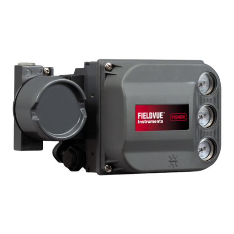
Fisher Fisher Fieldvue DLC3100 User guide

www.Fisher.com
Safety manual for Fisher™FIELDVUE™DLC3100
SIS Digital Level Controller
This supplement applies to
Instrument Level SIS
Device Type 130D
Device Revision 1
Hardware Revision 1
Firmware Revision 1.0.9
1. Purpose
This safety manual provides information necessary to design, install, verify, and maintain a Safety Instrumented
Function (SIF) utilizing the Fisher DLC3100 SIS digital level controller. It describes the conditions of use for the
DLC3100 SIS in safety applications. This document must be thoroughly reviewed and implemented as part of the
safety lifecycle. This information is necessary for meeting the IEC61508 or IEC61511 functional safety standards.
WARNING
This instruction manual supplement is not intended to be used as a stand-alone document. It must be used in conjunction
with the following documents:
Fisher DLC3100 Quick Start Guide (D104214X012)
Fisher DLC3100 Instruction Manual (D104213X012)
Failure to use this instruction manual supplement in conjunction with the above referenced documents could result in
personal injury or property damage. If you have any questions regarding these instructions or need assistance in obtaining
any of these documents, contact your Emerson sales office or Local Business Partner.
Other related documents include:
D Fisher 249 Caged Displacer Sensors Instruction Manual (D200099X012)
D Fisher 249 Cageless Displacer Sensors Instruction Manual (D200100X012)
D Fisher 249VS Cageless Displacer Sensor Instruction Manual (D103288X012)
D Fisher 249W Cageless Wafer Style Level Sensor Instruction Manual (D102803X012)
Instruction Manual Supplement
D104215X012
DLC3100 SIS Digital Level Controller
April 2018

Instruction Manual Supplement
D104215X012
DLC3100 SIS Digital Level Controller
April 2018
2
2. Description of the Device
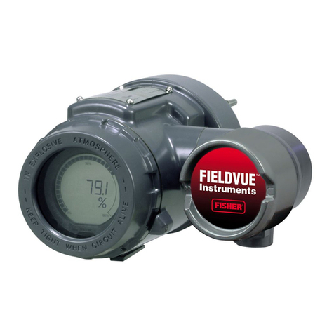
The Fisher DLC3100 SIS is a microprocessor-based digital level controller that measures and transmits change in liquid
level, or level of an interface between two liquids. Changes in the buoyancy of a displacer suspended in a vessel vary
the load on a torque tube assembly (249 sensors). The displacer with torque tube assembly and lever assembly
constitute the primary mechanical sensors. The angular rotational deflection of the torque tube is measured by the
instrument transducer, which consists of a magnet system moving over a Hall Effect sensor. In level measurement
mode, it is the proportion of displacer covered by liquid that produces the measured buoyancy.
DLC3100 SIS Default Settings
Application Level
Interface Level
Alarm Switch Low Alarm
High Alarm High Alarm
Safety Recovery Auto
Manual Manual
Trip Alarm Current
Settings
Device Malfunction Enable
Reference Voltage Failed Enable
PV Analog Output Readback Limit Failed Enable
Instrument Temperature Sensor Alert Enable
Hall Sensor Alert Enable
RTD Sensor Alert Enable
Hall Diagnostic Alert Enable
RTD Diagnostic Alert Enable
Program Memory Failed Enable
NVM Error Enable
RAM Test Error Alert Enable
Watchdog Reset Executed Enable
PV HiHi Alert Disable
PV LoLo Alert Disable

Instruction Manual Supplement
D104215X012
DLC3100 SIS Digital Level Controller
April 2018
3
3. Terms, Abbreviations, and Acronyms
249 Fisher caged and cageless displacer level sensors.
Device Response
TIme
Time required for the digital level controller to carry out its part of the safety function,
includes time taken to sense a change in input (lever assembly) and transmit a
corresponding output signal.
Diagnostic test
interval Time taken to detect internal faults.
DLC3100 SIS Digital level controller, product model designation for Safety Instrumented System
applications.
Fault Reaction Time Time taken to respond once a fault is detected.
FIT Failure In Time (1x10⁻⁹ failures per hour)
FMEDA Failure Mode Effect and Diagnostic Analysis
HART Highway Addressable Remote Transducer, open protocol for digital communication
superimposed over a direct current.
HFT Hardware Fault Tolerance
λFailure rate. λDD: dangerous detected; λDU: dangerous undetected; λSD: safe detected;
λSU: safe undetected.
Low Demand Mode Mode of operation of a safety instrumented function where the demands to activate the SIF
are less than once every two proof test intervals.
PFDAVG Average Probability of Failure on Demand
Process Safety Time
Period of time between a failure occurring in the system (with the potential to give rise to a
hazardous event) and the occurrence of the hazardous event if the safety function is not
performed
Safety Freedom from unacceptable risk of harm.
Safety Function
Function of a device or combination of devices intended to be used within a Safety
Instrumented System to reduce the probability of a specific hazardous event to an
acceptable level.
SFF Safe Failure Fraction
SIF Safety Instrumented Function
SIL Safety Integrity Level
SIS Safety Instrumented System
Type B Element “Complex” element (using complex components such as micro controllers or
programmable logic); for details see 7.4.4.1.3 of IEC 61508-2.

Instruction Manual Supplement
D104215X012
DLC3100 SIS Digital Level Controller
April 2018
4
4. Safety Requirements
Average Probability of Failure on Demand (PFDAVG)
Table 1 shows the achievable Safety Integrity Level (SIL) in Low Demand Mode of operation, depending on the average
probability of failure.
Table 1. Achievable Safety Integrity Level (SIL) in Low Demand Mode
Safety Integrity Level (SIL) PFDAVG with Low Demand Mode
4≥ 10-5 to < 10-4
3≥ 10-4 to < 10-3
2≥ 10-3 to < 10-2
1≥ 10-2 to < 10-1
Safety Integrity of the hardware
Table 2 shows the achievable Safety Integrity Level (SIL) depending on the Safe Failure Fraction (SFF) and the Hardware
Fault Tolerance (HFT) for safety related Type-B subsystems.
Table 2. Achievable Safety Integrity Level depending on the Safe Failure Fraction and Hardware Fault Tolerance
Safe Failure Fraction
Hardware Fault Tolerance (HFT)
A hardware fault tolerance of N means that N+1 faults could cause a loss of the safety function
0 1 2
< 60% Not Permitted SIL 1 SIL 2
60% - < 90% SIL 1 SIL 2 SIL 3
90% - < 99% SIL 2 SIL 3 SIL 4
≥ 99% SIL 3 SIL 4 SIL 4
5. Safety Characteristics
The specified characteristics are applicable under the following assumptions that have been made during the FMEDA.
D The mean time to restoration after a device has failed is 24 hours.
D The architectural constraint type for the DLC3100 SIS digital level controller is Low Demand mode.
D The hardware fault tolerance of the device is 0 (HFT = 0).
D To avoid unwanted or unauthorized modification, the set parameters must be protected.
D Proof test interval: ≤ 1 year.
D Safety accuracy: 2% of full span.
D Only a single component failure will fail the entire DLC3100 SIS digital level controller.
D Failure rates are constant, wear out mechanism is not included.
D Propagation of failures is not relevant.
D All components that are not part of the safety function and cannot influence the safety function (feedback
immune) are excluded.

Instruction Manual Supplement
D104215X012
DLC3100 SIS Digital Level Controller
April 2018
5
D Stress levels are average for an industrial environment and can be compared to the exida profile 2 with
temperature limits within manufacturer’s rating (see table 3 and 4 below). Other environmental characteristics
are assumed to be within manufacturer’s rating.
D A practical fault injection test can demonstrate the correctness of the failure effects assumed during the FMEDA
and the diagnostic coverage provided by the automatic diagnostics.
D The HARTrprotocol is only used for setup, calibration and diagnostics purposes, not for safety critical operation.
D The application program in the logic solver is constructed in such a way that Fail High and Fail Low failures are
detected regardless of the effect, safe or dangerous, on the safety function.
D Materials are compatible with process conditions.
D The device is installed, calibrated, and maintained per manufacturer's instructions.
D External power supply failure rates are not included.
D DLC3100 MTBF = 155 years
D Diagnostic Test Interval: Range from 500 milliseconds to 7 minutes
Table 3. exida Profiles, Electronic
exida Electronic Database
Profile According to
IEC60654-1
Ambient Temperature (_C) Temperature Cycle (_C/365
days)
Average
(External)
Mean
(Inside box)
1 B2 30 60 5
2 C3 25 30 25
3 C3 25 45 25
Profile 1: Cabinet mounted equipment typically has significant temperature rise due to power dissipation
but is subjected to only minimal daily temperature swings.
Profile 2: Low power electrical (two-wire) field products have minimal self heating and are subjected to daily
temperature swings.
Profile 3: General (four-wire) field products may have moderate self heating and are subjected to daily
temperature swings.
Table 4. exida Profiles, Mechanical
exida Mechanical Database
Profile According to
IEC60654-1
Ambient Temperature (_C) Temperature Cycle (_C/365
days)
Average
(External)
Mean
(Inside box)
1 B2 30 60 5
2 C3 25 30 25
3 C3 25 45 25
4 D1 25 30 35
Profile 1: Cabinet mounted equipment typically has significant temperature rise due to power dissipation
but is subjected to only minimal daily temperature swings.
Profile 2: Mechanical field products have minimal self heating and are subjected to daily temperature
swings.
Profile 3: Mechanical field products may have moderate self heating and are subjected to daily temperature
swings.
Profile 4: Unprotected mechanical field products with minimal self heating, are subject to daily temperature
swings and rain or condensation.

Instruction Manual Supplement
D104215X012
DLC3100 SIS Digital Level Controller
April 2018
6
6. Safety Instrumented System Design
Safety Instrumented System (SIS) is an implementation of one or more Safety Instrumented Functions. A SIS is
composed of any combination of sensor(s), logic solver(s), and final element(s), as shown in figure 1.
Figure 1. Example of Safety Instrumented System Components
DLC3100
SIS
249
When using the DLC3100 SIS in a safety instrumented system, the following items must be reviewed and considered.
D SIL Capability
D Safety Function
D Failure Rates
D Application Limits
D Environment Limits

Instruction Manual Supplement
D104215X012
DLC3100 SIS Digital Level Controller
April 2018
7
SIL Capability
D Systematic Integrity
SIL 2 Capable – The DLC3100 SIS digital level controller has met manufacturer design process requirements of
IEC61508 Safety Integrity Level 2.
D Random Integrity
The DLC3100 SIS digital level controller is classified as a Type B device according to IEC61508. The complete
element subsystem will need to be evaluated to determine the SFF. If the SFF of the subsystem is > 90% and
the PFDavg < 10-2, the design can meet SIL2 @ HFT = 0. If the SFF of the subsystem is between 60% and 90%,
and the PFDavg < 10-1, the design can meet SIL1 @ HFT = 0.
Safety Function
The safety function of DLC3100 SIS digital level controller is to measure level or interface of fluids and transmit a
4-20 mA analog signal within the safety accuracy (measurement accuracy ±2%). It includes the whole hardware and
software measurement chain from the displacer through the torque tube and the electronic board to the primary
analog output signal.
Table 5. Normal and Alarm States for FIELDVUE DLC3100 SIS Digital Level Controller
Output Function Normal State Safety Accuracy Alarm State(1)
4-20 mA
Level transmitter Actual fluid level ±2% >21.0 mA or <3.6 mA
1. Configurable high or low. Values are per NAMUR NE43.
Failure Rates
The failure rate data listed in table 6 and 7 is valid for the 15-year useful lifetime of the DLC3100 SIS digital level
controller. Its useful lifetime is highly dependent on the subsystem itself and its operating conditions. The failure rate
will increase after this time period. Reliability calculations based on the data listed in the FMEDA report for mission
times beyond the useful lifetime may yield results that are too optimistic.
Table 6. Failure Rates for FIELDVUE DLC3100 SIS Digital Level Controller
Failure Category Failure Rate (FIT)
Fail Safe Detected, λSD 0
Fail Safe Undetected, λSU 0
Fail Dangerous Detected, λDD 463
Fail Detected (detected by internal diagnostics) 230
Fail High (detected by logic solver) 83
Fail Low (detected by logic solver) 150
Fail Dangerous Undetected, λDU 39
No Effect 186
Annunciation Detected 33
Annunciation Undetected 14
SFF 92.2%

Instruction Manual Supplement
D104215X012
DLC3100 SIS Digital Level Controller
April 2018
8
Table 7. Failure Rates for Fisher 249 Displacer Sensors with DLC3100 Digital Level Controller
Failure Category High Trip
Failure Rate (FIT)
Low Trip
Failure Rate (FIT)
Fail Safe Detected, λSD 38 39
Fail Safe Undetected, λSU 10 8
Fail Dangerous Detected, λDD 570 568
Fail Detected (detected by internal diagnostics) 342 340
Fail High (detected by logic solver) 77 77
Fail Low (detected by logic solver) 151 151
Fail Dangerous Undetected, λDU 61 63
No Effect 205 205
Annunciation Detected 34 34
SFF 91.0% 90.7%
Application Limits
D Safety Instrumented Function design verification must be done for the entire collection of equipment used in the
Safety Instrumented Function including the DLC3100 SIS digital level controller. The SIS must fulfill the
requirements according to the Safety Integrity Level, especially the limitation of average Probability of Failure on
Demand (PFDavg).
D The DLC3100 SIS digital level controller can only be used for Level or Interface applications.
D The system response time is dependent on the entire final element subsystem. The user must verify the system
response time is less than the process safety time for each final element. The DLC3100 SIS digital level controller
safety function has a fault reaction time upon fault detection of < 1 second plus the mean time to repair.
D Measurement signal used by logic solver must be the analog 4-20 mA signal proportional to the fluid level.
D The logic solver must recognize both high/low alarms. If the logic solver loop uses IS barriers, caution must be
taken to ensure the loop continues to operate properly under the low alarm condition.
D Safe failure in which 4-20 mA current is driven out of range (<3.6 mA or > 21 mA).
D Device Response Time: less than 1 second
D When using the DLC3100 SIS in redundant applications, the owner-operator of the facility should institute
common causes training and more detailed maintenance procedures specifically oriented toward common
cause defense.
Environmental Limits
D Operating ambient temperature: -40_C to 80_C (-40_F to 176_F)
D Humidity: tested per IEC61298-3 Section 6
D Electromagnetic Compatibility: tested per IEC61326-3-2
D Vibration: tested per ISA 75.13 and FTEP 3B1

Instruction Manual Supplement
D104215X012
DLC3100 SIS Digital Level Controller
April 2018
9
7. Installation and Commissioning Guidelines
1. Verify that the DLC3100 SIS is suitable for use in Safety Instrumented Function
2. Verify nameplate markings are suitable for the hazardous location (if required)
3. Verify appropriate connections to the logic solver are made by referring to the instruction and safety manual of the
logic solver
4. For maximum availability and benefit of digital level controller features, the unit must be properly configured and
calibrated, the Instrument Mode set to In Service, and the protection enabled. With protection set, calibration and
other protected parameters cannot be changed, including Instrument Mode.
5. The sensor safety function of the DLC3100 SIS along with the SIS safety function must be tested after installation to
ensure that it meets safety demand and applicable process safety time requirements.
8. General Requirements
Refer to Fisher DLC3100 quick start guide and instruction manual for mounting to a 249 sensor, starting up, and
configuring and calibrating the DLC3100 SIS.
DLC3100 SIS digital level controllers shall be mounted so that they are easily accessible for service, configuration, and
monitoring. Exposure to corrosive atmosphere, excessive vibration, shock, or physical damage shall be prevented.
9. Operation, Periodic Inspection, Test, and Repair
Periodic testing, consisting of proof test, is an effective way to reduce the PFDavg of the DLC3100 SIS instrument as
well as the 249 sensors connected to it. The SIL for the DLC3100 SIS is based on the assumption that the end user will
carry out these tests and inspection at least once per year. The system check must be carried out to prove that the
safety functions meet the IEC specification and result in the desired response of the safety system as a whole. Results
of periodic inspections and tests should be recorded and reviewed periodically.
Maintenance
DThe effective time to restore the DLC3100 SIS is approximately 24 hours. This comprises of disassembly, repair,
reassembly, and recalibration.
DDigital level controller preventive maintenance consists, at a minimum, of replacing all critical elastomeric seals
and a visual inspection of moving components to verify satisfactory condition. The SIS Preventive Maintenance
Kit includes all elastomeric seals and is available through your local Emerson sales office. Following maintenance,
the digital level controller must be calibrated per the calibration menu. After calibration, the digital level
controller functional safety must be validated.
DA conservative approach is taken in estimating the service interval for the digital level controller in Safety
Instrumented Systems. For SIS applications, preventive maintenance must be performed on the digital level
controller at eight to ten year intervals from the date of shipment. If the instrument is exposed to the upper or
lower extremes of the environmental limits, the interval for preventive maintenance may need to be reduced.
Protection
When protection is enabled, setup and calibration of the DLC3100 SIS are not permitted by local user interface or by
remote HART communication. Only reading data is allowed. The LCD display will show a lock icon ( ) to indicate that
the DLC3100 SIS is currently protected.
Instruction Manual Supplement
D104215X012
DLC3100 SIS Digital Level Controller
April 2018
10
Decommissioning Guidelines
When decommissioning a DLC3100 SIS instrument, proper procedures must be followed. Decommissioning includes
the following steps:
1. Avoid personal injury or property damage from sudden release of process pressure or bursting of parts. Before
proceeding with any decommissioning procedures:
D Always wear protective clothing, gloves, and eyewear to prevent personal injury or property damage.
D Do not remove the sensor from the process while the vessel is still pressurized.
2. Bypass the sensor subsystem or take appropriate action to avoid a false trip
3. Bypass the safety function of the level measurement or take appropriate action to avoid a false trip.
4. Disconnect the electrical wiring to and from the DLC3100 SIS instrument.
5. Remove the DLC3100 SIS instrument, mounting parts from the sensor assembly.
Application
The DLC3100 SIS digital level controller can be applied to most process or storage vessels, bypass chambers, and
interfaces up to the unit pressure and temperature ratings. The DLC3100 SIS with 249 sensor can be used for liquids,
clean or dirty, light hydrocarbons to heavy acids to meet the safety system requirements of IEC61508.
Benefits
The DLC3100 SIS provides the following benefits to operation:
D Suitable for use in environments up to SIL 2 (Safe Failure Fraction = 92.2%) as independently assessed (full
assessment) by exida.com as per IEC61508/61511-1.
D Continuous self-test with > 21 mA or < 3.6 mA fault indication fully compliant with NAMUR NE-43.
D Intrinsic Safe, Explosion-proof approvals.
D Two-wire, loop-powered transmitter for level, interface measurement.
Proof testing
According to section 7.4.5.2f of IEC61508-2, proof tests must be undertaken regularly to reveal dangerous faults
which are undetected by diagnostic tests. Proof test coverage is a measure of how many undetected dangerous
failures are detected by the proof test. It is a testing of safety system components to detect any failures not detected
by automatic online diagnostics followed by repair of those failures to an equivalent as-new state. A proof test is a test
that is manually initiated. It is an effective way to reduce the PFDavg of the DLC3100 SIS instrument. As part of the
test, the capability of the SIF to achieve the defined safe state must be verified. The Safety Function must be verified.
The proof test interval must be established for the SIF based on the failure rates of all the elements within the function
and the risk reduction requirements. This determination is a critical part of the design of the SIS. A proof test will
detect 95% of possible dangerous failures undetected in the DLC3100 SIS digital level controller with Fisher 249
displacer sensors. Proof testing is a vital part of the safety lifecycle and is critical to ensuring that a system achieves its
required safety integrity level throughout the safety lifecycle.

Instruction Manual Supplement
D104215X012
DLC3100 SIS Digital Level Controller
April 2018
11
Note
Any time the SIF needs to be disabled, such as to perform a proof test or to take corrective action, appropriate measures must be
taken to ensure the safety of the process.
Note
To ensure corrective action, continuous improvement, and accurate reliability prediction, the user must also work with their local
Emerson Automation Solutions service representative to see that all failures are reported.
Test steps for the Fisher DLC3100 SIS
Following are the steps to detect Dangerous Undetected (DU) failure. The procedure will detect approximately 95% of
possible DU failures in the DLC3100 SIS digital level controller with Fisher 249 displacer sensors.
Proof Test Procedure:
1. Bypass the safety function and take appropriate action to avoid a false trip and any safe actions against
dangerous atmospheres.
2. Inspect the instrument for dirty or clogging parts, adequate wiring, correct mounting of end connections and
other physical damage.
3. Observe the tightening torques for the nuts and studs.
4. Use HART communications to retrieve Alarm High / Low setting, any diagnostics alerts and take appropriate
action. Alarm High / Low setting should be checked against the plant safety requirement for that particular
application. If setting is High, go to step 5. If setting is Low, go to step 6.
5. Retrieve PV HiHi alert setting. Send a HART command (Enable Trip Alarm Current and set PV HiHi alert threshold
to activate the PV HiHi alert) to the transmitter to go to the high alarm current output and verify that the analog
current reaches that value. This will test for compliance voltage problems such as a low loop power supply
voltage or increased wiring resistance. Continue to step 7.
6. Retrieve PV LoLo alert setting. Send a HART command (Enable Trip Alarm Current and set PV LoLo alert threshold
to activate the PV LoLo alert) to the transmitter to go to the low alarm current output and verify that the analog
current reaches that value. This will test for possible quiescent current related failures.
7. Perform a two-point calibration of the displacer and digital level controller over the full working range using
process fluids. If the calibration is performed by any means other than fluids acting on the displacer, Trim Zero
calibration has to be done when it is put back to actual process fluids.
8. Perform a five-point calibration check. If the calibration check is correct, the proof test is complete. Proceed to
step 10. If the calibration check is incorrect, remove the displacer and digital level controller from the process.
Inspect for damage, buildup or clogging. Clean it if necessary. Examine the torque tube and the displacer to
detect corrosion or leaks (replace if necessary). Observe the tightening torques for the nuts and studs. Perform a
two-point calibration of the displacer and digital level controller over the full working range using process fluids.
9. If the calibration check is off by more than 2%, contact the factory for assistance. If the calibration check is
correct, the proof test is complete.
10. Reinstall the displacer and digital level controller if the assembly was removed previously. Ensure the Alarm
setting is correct and reinstate the PV HiHi/LoLo Alert settings.
11. Lock the settings by write protection.
12. Remove the bypass and otherwise restore normal operation.

Instruction Manual Supplement
D104215X012
DLC3100 SIS Digital Level Controller
April 2018
12
Emerson Automation Solutions
Marshalltown, Iowa 50158 USA
Sorocaba, 18087 Brazil
Cernay, 68700 France
Dubai, United Arab Emirates
Singapore 128461 Singapore
www.Fisher.com
The contents of this publication are presented for informational purposes only, and while every effort has been made to ensure their accuracy, they are not
to be construed as warranties or guarantees, express or implied, regarding the products or services described herein or their use or applicability. All sales are
governed by our terms and conditions, which are available upon request. We reserve the right to modify or improve the designs or specifications of such
products at any time without notice.
E2017, 2018 Fisher Controls International LLC. All rights reserved.
Fisher is a mark owned by one of the companies in the Emerson Automation Solutions business unit of Emerson Electric Co. Emerson Process Management,
Emerson, and the Emerson logo are trademarks and service marks of Emerson Electric Co. HART is a registered trademark of FieldComm Group. All other
marks are the property of their respective owners.
Neither Emerson, Emerson Automation Solutions, nor any of their affiliated entities assumes responsibility for the selection, use or maintenance
of any product. Responsibility for proper selection, use, and maintenance of any product remains solely with the purchaser and end user.
Table of contents
Other Fisher Controllers manuals

Fisher
Fisher L2e User manual

Fisher
Fisher 67D Series User manual

Fisher
Fisher EZL User manual

Fisher
Fisher DPR900 User manual

Fisher
Fisher 1290 User manual

Fisher
Fisher FIELDBUE DVC6200 User manual

Fisher
Fisher 1051 User manual

Fisher
Fisher 657 Sizes 80 User manual

Fisher
Fisher R130/21 User manual

Fisher
Fisher 1061 User manual

Fisher
Fisher 1066 User manual

Fisher
Fisher 1052PSV User manual

Fisher
Fisher ED User guide

Fisher
Fisher 1061 User manual

Fisher
Fisher FIELDVUE DVC6200 User manual

Fisher
Fisher 644 User manual

Fisher
Fisher FIELDVUE DLC3010 User manual

Fisher
Fisher D500243X012 User manual

Fisher
Fisher 6492HTM User manual

Fisher
Fisher EZR Series User manual