manuals.online logo
Brands
  1. Home
  2. •
  3. Brands
  4. •
  5. Fisher
  6. •
  7. Controllers
  8. •
  9. Fisher 480 User manual

Fisher 480 User manual

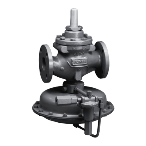
Types 480,481, & 489
Fisher Controls
Instruction Manual
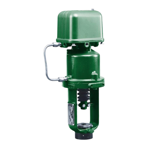
Type 480,481, and 489
Actuators
I FISHER”~
March 1971 Form 2367A
Actuator Specifications
Type NumberDescription
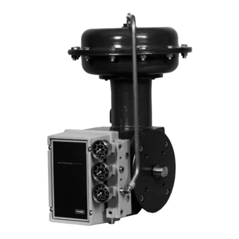
480 Pneumattralfy o~~tatecl f>iston
actuator with l”tEgrafly
mounted Type 3570 positioner.
Actuator is yokeless, has 4”
maxfmum trael. and is fastened
10 the actuatw mounting plate
of many prel970 Veer
-Ball@ ~afves and Fisher butter-
fly valves. Actuator sizes 30.
40, 60. 80, 100, and 130.
481 Same as Type 480, hut for
on/off service. Positmner is re-
placed with a pressure tap cwer
which is Molted to the top of the
cylinder.
489 Same as Type 480. but pow
tioner is replaced with Type
3579 solenoid manifold which
permfs supply pressure to be
loaded and exhausted in rep
sponse to electrical signals.
3570
Standard positioner basic to
Tvpe 480 actuators.
3579 Standard solenoid manifold
basic to Type 489 actuatws.
Installation
Inspect this equipment on arrival to
Nate any damage which may have oc-
curred in transit. If the actuator is at-
tached to a valve body when received.
install the valve in the pipeline with
flow in the direction of the an~w on
the salve body. (Some valve types,
notably various butterfly valves. can
be installed with flow in either direc-
tion and are unmarked as to proper
flow direction.)
A three-valve bypass around fhe
main valve is recommended to permit
c~nt~nu~~s operation during periodic
matntenance or inspection of the main
valw
When Series 480 actuators are sup-
plied to operate dampers, louvers. or
similar equipment, a suitable mounting
plate should be provided, and the
piston rod of the actuatw connected
to the operating arm of the damper,
etc., with appropriate hnkage.
Principle of Operation
Type 480..
ISee Figure II - The pneumatic
pressure signal from the instrument or
controller is piped to the bellows of
the 3570 positioner. Assume that the
porltmner IS direct-acting and that the
instrument signal has increased. The
bellows expands and m~,ves the beam,
which pivots around the fixed pmnt
and simultaneously uncwers the nw
zle of relay “B” and COYUSthe nozzle
of relay “A”. Relay “A” nozlle pres-
sure increases due tq the restriction
created by the beam over the nuzzle.
Through relay action, the air pressure
tO the top of the piston increases. Rep
lay “B” reacts to the change in beam
pqsltx,” to decrease the prersure on
the underside of the piston. Due to the
unbalanced pressures acting on the
plst~n, it mwes down, changing the
position of the actuator stem and re-
turning the controlled element to the
desired value.
A feedback arrangement consisting
of a range spring between the beam
and the piston rod extension prevents
over-correction and ensures a definite
position of the piston for a given
Types
480,481, & 489
instrument signal. thus giving stable
and accurate response to a change in
controlled conditions.
Upon receiving a decreasing instru-
ment signal, the reverse of the above
actlo” takes place. The bellows con-
tracts and the beam pivots, restricting
the nozzle of relay “B” and
uncovering the nozzle of relay “A”.
Through relay action. the pressure be-
low the actuator piston increases and
the pressure above the piston decreases
to move the piston upward.
Types 481 and 489..
ISee Figure 21. Operation of either
a Type 481 or a Type 489 is similar to
a Type 480 in so far as basic piston
movement is concerned. However, the
manners of loading the respective
pistons are less complex. On the Type
489 actuators. the 3579 solenoid
manifold acts to alternately load and
exhaust full supply pressure to op-
posite sides of the piston in response
to electrical signals from an outside
power source. The 481, used most
frequently for on/off service, must
have an external switching device
attached to divert supply pressure
from one side of the piston to the
other.
Figure 2 ///ustra don of a Type 3579 manifold asserr~bly.
Pressure Connections
Type 48%.
The Type 3570 positioner, an ins
tegral part of Type 480 actuator units,
is factory-assembled to the actuator.
Two connections, “Supply” and
“Instrument”. remain to be made after
valve installation. Both are 114” NPT
holes in the positioner and are label-
led. Minimum supply pressure is 35
psig. but for optimum performance,
supply pressure should be held as near
as possible to the 150 psig maximum.
Supply pressure air or gas should be
clean and dry, as well as non-corrosive.
Use of a Fisher Type 254 filter is rep
commended.
The positioner case should al-
ways be vented to prevent pressure
buildup. If the valve is installed with
the actuator below the pipeline, pro-
vide a new vent location in the lowest
part of the case by removing the
cadmium plated pipe plug from the
case and screwing it into the standard
vent location. This also serves as a
drain hole to prevent accumulationof
condensate.
Types 481 and 489..
The Type 481 and Type 489
actuators also require l/4” NPT male
Supply pressure piping. The 3579
solenoid manifold used or the Type
489 has three external connections.
Supply air enters the side of the ~nant~
fold. Depending on the controller
signal to the solenoid YBIYBS. the XIII-
ply air is directed either straight down
to the top side of the piston. or out
the bottom cylinder connection lin
side of manifold adjacent to supply
port) and through tubing to the lower
side of the piston. During loading of
piston, the air on the opposite side of
the piston is exhausted through the w
haust port of the manifold.
The Type 481 has only a pressure
tap cover on top of the cylinder. Sups
ply air pressure must be connected to
it. and also to the lower cylinder con-
nection located near the cylin-
der/cylinder flange joint. An external
four-way valve or other switching de-
we must be provided between the
maw supply pressure line and these
two actuator pressure connect,ons.
Adjustments
All three adjustments on the Type
480 actuator are on the Type 3570
positioner. For further information on
the positioner, such as Adjustments.
Maintenance. Reversing. and Relay
Operation, refer to the Type 3570 Ins
structions and Parts List, Form 1837.
Types 481 and 489 require no ad-
justments.
Actuator Maintenance
It is necessary for efficient and
proper operation of the actuator that
all parts be free from dirt, abrasives.
and foreign materials. Upon assembly
at the factory. all synthetic rubber
O-rings have been coated with LUB-
RIPLATE 130.AA, a special lubricant
manufactured and distributed by Fiske
Brothers Refining Company of
Newark. New Jersey, and Toledo.
Ohio. It is recommended that his lubri-
cant ,be used on all O-rings, especially
those on moving parts or in contact
with moving parts. whenever the ac-
tuator is dismantled.
To disassemble a Fisher piston ac-
tuator, proceed as follows:
(References to “positioner” can be
ignored if either a 481 or a 489 ac-
tuator is involved.1
1. Bypass the valve body or shut
off the pressure in the pipeline.
Caution: The adjustable linkage be-
tween the actuator and the main valve
should not be disconnected when the
valve is open with fluid flowing.
(Dampers or louvers should be in safe.
stable positions prior to discon-
nection.)
2. Shut off all pressure to the ac-
tuator. Remove all tubing lines
Icylinder. instrument, and supply)
from the actuator.
3. Remove positioner cover after
loosening the four cover screws on the
underside of the positioner base.
4. Disengage range spring by un~
screwing the spring retainer from the
piston rod extension.
5. Loosen the two cap screwy that
hold the positioner to the cylinder.
When removing the positioner. do not
lose the small O-ring that is used in the
passage from the positioner to the top
of the cylinder.
6. Next remove the clevis bolt
from the adjustable linkage. Remove
the bottom snap ring (Key 26) and un-
screw the cleuis and the boot locknut
from the actuator piston rod.
7. Remove the nuts that hold the
cylinder to the mounting flange and
lift off the cylinder.
8. Remove the stud bolts (Key 13)
that hold the cylinder to the cylinder
flange. Two slots. 180” afx,rt. are lo
Types 480,481, & 489
cated at the lower edge of the
cylinder. Insert a screwdriver in these
slots and pry the cylinder loose. The
pet011 and piston rod will come out
with the cylinder. The piston can then
be removed by pulling it out the open
end of the cylinder,
9. Unscrew both seal bushings,
(Keys 7 and 8).
10. Inspect all parts for eXcessi”e
wear and defects. Replace all worn
O-rings. Lubricate as mentioned above.
11, To reassemble, reverse the
above procedure.
Serial Numbers
Always include the serial number of
your actuator when consulting your
representative for technical advice or
ordering replacement parts. Also in-
clude the complete part number listed
in, the following parts reference sec.
fion. (Some valve types. notably
butterfly valves. do not have the same
valve serial number as the actuator.
Therefore. for proper cross reference,
always include the valve serial number
if it differs from the actuator serial
number.)
Parts Reference Types 480, 481, and 489
Types 480, 481, & 489
Parts Reference
Figure 4. Type 481 actuator. Sizes 30,40 and 60.
Parts Reference
(Continued)
45 SpringRetainerSpacer.SST
,T”pe480only1For 2”
0‘ lesstrwe, .,.I2233 4617
78’ coversea,.S”“. Rubber
(Type481onlyl lCS5380699
79 coverscrew.Steel.CDPL
lT”w 481only, ?A34492405
160 PipePlug.Steel IA6496 2899
‘ RecommendedSparePart

This manual suits for next models

2

Other Fisher Controllers manuals

Fisher 4195 KB Series User manual

Fisher

Fisher 4195 KB Series User manual

Fisher 670F User manual

Fisher

Fisher 670F User manual

Fisher 655 User manual

Fisher

Fisher 655 User manual

Fisher 1052PSV User manual

Fisher

Fisher 1052PSV User manual

Fisher 2502 Series Level-Trol User manual

Fisher

Fisher 2502 Series Level-Trol User manual

Fisher 1066 User manual

Fisher

Fisher 1066 User manual

Fisher 1051 User manual

Fisher

Fisher 1051 User manual

Fisher 1078 User manual

Fisher

Fisher 1078 User manual

Fisher 3570 User manual

Fisher

Fisher 3570 User manual

Fisher 1098H-EGR User manual

Fisher

Fisher 1098H-EGR User manual

Fisher D500243X012 User manual

Fisher

Fisher D500243X012 User manual

Fisher 4194B Series User manual

Fisher

Fisher 4194B Series User manual

Fisher 1061 User manual

Fisher

Fisher 1061 User manual

Fisher 6492HTM User manual

Fisher

Fisher 6492HTM User manual

Fisher 1301F User manual

Fisher

Fisher 1301F User manual

Fisher EZR User manual

Fisher

Fisher EZR User manual

Fisher 667 User manual

Fisher

Fisher 667 User manual

Fisher 685 User manual

Fisher

Fisher 685 User manual

Fisher EZR Series User manual

Fisher

Fisher EZR Series User manual

Fisher FIELDVUE DLC3010 User manual

Fisher

Fisher FIELDVUE DLC3010 User manual

Fisher 656 User manual

Fisher

Fisher 656 User manual

Fisher 133H User manual

Fisher

Fisher 133H User manual

Fisher EMERSON VSX4 Series User manual

Fisher

Fisher EMERSON VSX4 Series User manual

Fisher R130/21 User manual

Fisher

Fisher R130/21 User manual

Popular Controllers manuals by other brands

Wind Mobility Technology H1 product manual

Wind Mobility Technology

Wind Mobility Technology H1 product manual

Metso VALVCON V-Series Installation, maintenance & operating instructions

Metso

Metso VALVCON V-Series Installation, maintenance & operating instructions

Grundfos DPC 1-3 Installation & operating instruction

Grundfos

Grundfos DPC 1-3 Installation & operating instruction

Performance Computer PT-VME151A user manual

Performance Computer

Performance Computer PT-VME151A user manual

CR-Tec ER PREMIER ER20 Installation and operation manual

CR-Tec

CR-Tec ER PREMIER ER20 Installation and operation manual

B-TEC Starter 01 manual

B-TEC

B-TEC Starter 01 manual

DoorKing 1838 Installation & owner's manual

DoorKing

DoorKing 1838 Installation & owner's manual

artisan 5400 user manual

artisan

artisan 5400 user manual

Lucenti BLACKWAVE PIXLDRIVE1 user manual

Lucenti

Lucenti BLACKWAVE PIXLDRIVE1 user manual

Wintriss wpc 2000 user manual

Wintriss

Wintriss wpc 2000 user manual

Nevco 475 Baseball Operator instructions

Nevco

Nevco 475 Baseball Operator instructions

YASKAWA V1000 Series Technical manual

YASKAWA

YASKAWA V1000 Series Technical manual

Maple Systems HMI5000P Series Information sheet

Maple Systems

Maple Systems HMI5000P Series Information sheet

AKO AKO-14545 user manual

AKO

AKO AKO-14545 user manual

Sinovo SD200 Series user manual

Sinovo

Sinovo SD200 Series user manual

NookBox MDC-1 installation guide

NookBox

NookBox MDC-1 installation guide

Emerson El-O-Matic E Series SIL Safety Manual

Emerson

Emerson El-O-Matic E Series SIL Safety Manual

SMC Networks ITV1000-52 Series Operator's manual

SMC Networks

SMC Networks ITV1000-52 Series Operator's manual

manuals.online logo
manuals.online logoBrands
  • About & Mission
  • Contact us
  • Privacy Policy
  • Terms and Conditions

Copyright 2025 Manuals.Online. All Rights Reserved.