manuals.online logo
Brands
  1. Home
  2. •
  3. Brands
  4. •
  5. Fisher
  6. •
  7. Controllers
  8. •
  9. Fisher 912 Series User manual

Fisher 912 Series User manual

D100317X012
912 Series
e
Fisher
Controls
International,
Inc.
1979,
1991;
All
Rights
Reserved
Fisher Controls Instruction Manual
912 Series
Pressure Regulators
May 1991 Form 5124
R
WARNING
Toavoid injury or equipment damage, these
regulators should be installed, operated, and
maintained in accordance with federal, state
and local codes, rules and regulations, and
Fisher instructions. Only aqualified person
must install or service aregulator.Be certain the
control spring range label is updated to accu-
rately indicate any field changes in equipment,
materials, service conditions, or pressure set-
tings.
Immediately call aqualified technician in case
of trouble. If venting occurs, or aleak develops
in the system, it indicates that service is re-
quired. Failure to correct the situation immedi-
ately may create ahazardous condition.
INTRODUCTION
Scope of Manual
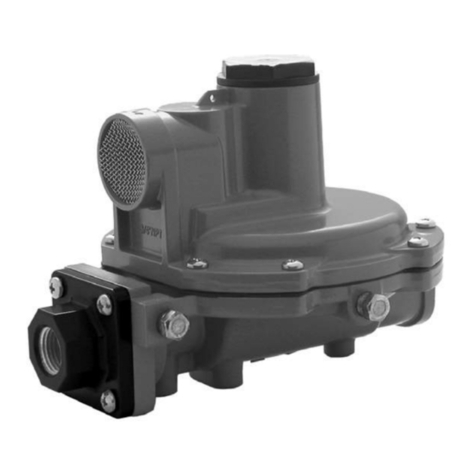
This manual provides installation, maintenance, and parts
information for the 912 Series pressure regulators (figure 1)
as used in industrial/natural gas applications.
Description
The 912 Series pressure regulators are self-operated,
spring-loaded devices built to provide accurate, sensitive
control suited to avariety of applications.
Asoutletpressure beginsto exceed the setpressure, the
diaphragminside the regulatorlifts,operatingaleverto
W2217
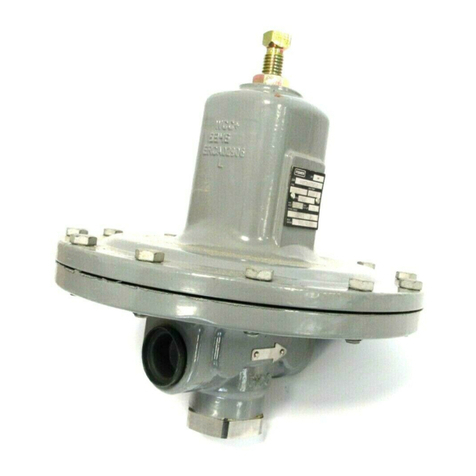
Figure 1. Type 912 Regulator
close the inlet. Pressure in excess of the relief valve spring
force opens the relief valve, allowing excess pressure to
bleed through the screened vent in the spring case.
Specifications
Specifications for the 912 Series pressure regulators are
listed in table 1.
INST ALLA TION
WARNING
Personal injury or equipment damage may re-
sult if the regulator is installed where service
conditions could exceed the pressure or tem-
perature specifications in table 1. The regulator
must not be used for hazardous gas service in
aclosed area unless the vent is piped to asafe
912 Series
R
2
Table 1. Specifications
AVAILABLE See table 2
CONFIGURA TIONS
BODY SIZES AND END Inlet: 1/4-inch NPT screwed
CONNECTION STYLES Outlet: J1/4 or J3/8-inch NPT
screwed
MAXIMUM 250 psig (17 bar)
ALLOW ABLE INLET
PRESSURE
OUTLET PRESSURE See table 2
RANGES
MAXIMUM Maximum Emergency Outlet
ALLOW ABLE OUTLET Pressure: 20 psig (1.4 bar)
PRESSURE Maximum Recommended Outlet
Pressure to Avoid Internal Part
Damage: 3psi (0.21 bar,differ-
ential) above outlet pressure setting
INTERNAL RELIEF Approximate Internal Relief Valve
PERFORMANCE Start-to-Discharge Point: See
table 2
Capacity: Adequate only for relieving
minor buildup situations such as are
caused by chips or dirt blocking the
seat partly open; for major malfunctions,
external relief is required according to
the ‘‘Installation’’section.
MA TERIAL -20 to 160_F(-29 to 71_C)
TEMPERA TURE
CAP ABILITIES
PRESSURE Internal
REGISTRA TION
APPROXIMA TE 1.3 pounds (0.6 kg)
WEIGHT
Table 2. Outlet Pressure Range Data
A
V
AILABLE
CONFIGURA
TION
OUTLET
PRESSURE
RANGE
APPROXIMA TE POINT ABOVE
OUTLET PRESSURE SETTING
A
T
WHICH
INTERNAL
RELIEF
CONTROL SPRING
SELECTION
A
V
AILABLE
CONFIGURA
TION
OUTLET
PRESSURE
RANGE
ATWHICH INTERNAL RELIEF
ST ARTS TODISCHARGE Part Number Color Code
Type 912 without handwheel
3to 7inches w.c. (7 to 17 mbar)
5to 10 inches w.c. (12 to 25 mbar)
9.25 to 13 inches w.c. (23 to 32 mbar)
12 to 24 inches w.c. (30 to 60 mbar)
5to 21 inches w.c. (12 to 52 mbar)
8to 30 inches w.c. (20 to 75 mbar)
16 to 39 inches w.c. (40 to 97 mbar)
17 inches w.c. to 3psig (42 to 210 mbar)
1B7843 27222
1B7844 27222
1L5079 37022
1B7845 27222
Red
Orange
Cadmium
Blue
Type 912H without handwheel 1to 2.5 psig (69 to 172 mbar)
2.7 to 5psig (186 to 340 mbar)
0.7 to 6.8 psig (0.05 to 0.47 bar)
3.8 to 12.5 psig (0.26 to 0.86 bar)
1B7846 27222
1B7847 27222
Yellow
Green
912 Series with handwheel 0to 1psig (0 to 69 mbar)
0to 5psig (0 to 340 mbar)
0to 3psig (0 to 210 mbar)
0to 12.5 psig (0 to 0.86 bar)
1C5804 27222
1C5805 27012
Black
Brown
area. The vent opening on the regulator or the
opening on the remote vent pipe (if one is used)
should be pointed down to minimize clogging
from collected moisture, corrosive chemicals,
or other foreign material. Overpressuring the
downstream system (and risk of explosion)
could result from aclogged vent.
Overpressuring any portion of aregulator or
associated equipment may cause leakage, part
damage, or personal injury due to bursting of
pressure-containing parts or explosion of accu-
mulated gas.
Like most regulators, the 912 Series regulators have an out-
let pressure rating lower than the inlet pressure rating.
Downstream protection is required if the actual inlet pres-
sure can exceed the regulator outlet pressure rating or the
pressure rating of any downstream equipment.
Regulator operation within ratings does not preclude the
possibility of damage from external sources or from debris
in the lines. Aregulator should be inspected for damage pe-
riodically and after any overpressure condition.
Ensure that the regulator is undamaged and contains no
foreign material. Install the regulator so that flow through it
leaves the outlet port (marked on the body). The regulator
may be installed in any position, however,the spring case
vent should be pointed down. Spring case/vent orientation
can be changed by rotating the spring case with respect to
the body.
For an indoor installation, if the regulator controls agas that
is flammable or otherwise hazardous, aspring case with the
optional tapped vent should be used so that the exhaust can
be piped away.Provide protection on a remote vent by
installing ascreened vent cap into the remote end of the
vent pipe. The vent should be pointed down.
Apply a good grade of pipe compound to the pipe threads
before making the connections. Install piping into the
1/4-inch NPT inlet connection and the 1/4-inch or 3/8-inch
NPT outlet connection.
912 Series
3
Each regulator is factory-set for the pressure setting speci-
fied on the order.Ifno setting was specified, the outlet pres-
sure is factory-set at the mid-range of the control spring.
The procedure for adjusting the output pressure is given in
the ‘‘Startup’’section.
ST ARTUP
Key numbers are referenced in figure 2.
With installation completed and downstream equipment
properly adjusted, slowly open the upstream and down-
stream shutoffvalves while monitoring the regulator output
pressure.
WARNING
For the 912 Series constructions with no drive
screw in the spring case, never adjust the con-
trol spring to produce an outlet pressure higher
than the outlet pressure range for that particular
spring. Doing so could overpressure the system
and cause personal injury or equipment dam-
age. If the desired outlet pressure is not within
the range of the control spring, install aspring of
the proper range according to the ‘‘Mainte-
nance’’section.
If outlet pressure adjustment is necessary,monitor the out-
let pressure with a gauge while performing the following
procedure:
1. For units without ahandwheel, unscrew the closing cap
(key 3) and insert ascrewdriver blade into the adjusting
screw (key 4).
2. Slowly turn the adjusting screw or handwheel clockwise
to increase or counterclockwise to decrease the output
pressure setting.
3. With the output pressure adjusted to the desired value,
replace the closing cap on units without ahandwheel.
SHUTDOWN
Close the nearest upstream shutoffvalve, then close the
nearest downstream shutoffvalve, and vent pressure from
the outlet of the regulator.
MAINTENANCE
Regulator parts are subject to normal wear and must be in-
spected and replaced as necessary.The frequency of in-
spection and replacement of parts depends on the severity
of service conditions or the requirements of local, state, and
federal rules and regulations.
WARNING
Toavoid personal injury or equipment damage,
do not attempt any maintenance or disassembly
without first isolating the regulator from system
pressure and relieving all internal pressure from
the regulator.
This procedure is to be performed if changing the control
spring for one of adifferent range, or for inspecting, clean-
ing, or replacing any other parts. Key numbers are refer-
enced in figure 2.
Note
If sufficient clearance exists, the regulator body
(key 1) can remain in the line during spring re-
placement or other maintenance procedures.
Control Spring Replacement
On units without the handwheel, unscrew the closing cap
(key 3) and turn the adjusting screw out of the spring case.
Lift out the control spring (key 5).
On units with ahandwheel, turn the handwheel counter-
clockwise until the tension is relieved from the control
spring. Unscrew the nut at the base of the handwheel and
lift the handwheel offthe spring case. Lift out the adjusting
screw and the control spring.
Replace the control spring and complete the assembly by
replacing the adjusting screw and the closing cap or hand-
wheel. Adjust the spring tension as described in the ‘‘Start-
up’’section.
Diaphragm and Relief Valve
Replacement
Remove cap screws (key 14) and separate the spring case
from the valve body.Remove the control spring (key 5) and
the diaphragm (key 15) along with the diaphragm head (key
10), the relief valve seat (key 9) and the relief valve spring
(key 6). Separate these parts by removing the pin (key 8)
and the spring seat (key 7). Remove the disk holder assem-
bly (key 11) by removing two screws (key 13).
912 Series
R
4
Tore-assemble the regulator,first assemble the relief valve
spring assembly,then replace the relief valve spring assem-
bly,the disk holder assembly,the diaphragm, the dia-
phragm head, and fit the spring case to the body.Install and
tighten cap screws (key 14) in acriss-cross manner.Adjust
the control spring tension as described in the ‘‘Startup’’sec-
tion.
PARTS ORDERING
When corresponding with the Fisher representative about
this regulator,include the type number,date of manufac-
ture, and all other pertinent information from the labels.
Specify the eleven-character part number when ordering
new parts from the following parts list. Figure 2. 912 Series Pressure Regulator Assembly
BD4632-H
Key Description Part Number
14 Machine Screw,steel pl
(6 req’d) 1B7839 28982
15 Diaphragm, rubber 1B7837 02012
16 Vent Screen,
Monel 0W0863 43062
17* Closing Cap Gasket, asbestos (use
with tapped vent only) 1E7652 04022
18 Closing Spring, SST,912 Series
w/handwheel, only 1E3020 37022
19 Spacer Ring, brass, 912 Series
w/handwheel, only 1C5807 14012
20 Lockwheel, brass, 912 Series
w/handwheel, only 1C2346 14012
22 Warning Label
(not shown) 1P4879 06032
23 Spring Range Label (not shown)
1to 2.5 psi (69 to
172 mbar) T10800 06992
2.7 to 5psi (186 to
340 mbar) T10801 06992
0to 1psi (0 to
69 mbar) T10802 06992
0to 5psi (0 to
340 mbar) T10803 06992
25 Spring Seat, brass, 912 Series
w/handwheel 1C2345 14012
PARTS LIST
Key Description Part Number
1Body,zinc
1/4 x1/4-inch NPT
0.073 inch (1.8 mm)
port dia 3D3771 44042
1/4 x3/8-inch NPT
0.073 inch (1.8 mm)
port dia 3B7824 44042
2Spring Case, zinc
For use with control springs
1B7847 27222 (complete with drive
screw)
Untapped 1B7840 T00012
1/8-inch NPT tapped
vent T10895 T00012
For all other constructions
Untapped 3E2944 44042
1/8-inch NPT tapped
vent 1E2955 44042
3Closing Cap
912 Series w/handwheel,
brass 1C2344 14012
All others, plastic T10276 06992
4Adjusting Screw
912 Series w/handwheel, zinc
&steel 1B7992 000A2
All others, plastic T10277 06992
Key Description Part Number
5Regulator Spring, steel pl.
9.25 to 13 inch w.c. (23 to 32 mbar),
cad. 1L5079 37022
3to 7inch w.c. (7 to 17 mbar),
red 1B7843 27222
5to 10 inch w.c. (12 to 25 mbar),
orange 1B7844 27222
10 inch w.c. to 1psi (25 to 69 mbar),
blue 1B7845 27222
0.5 to 2.7 psig (35 to 186 mbar),
yellow 1B7846 27222
0to 1psig (0 to 69 mbar),
black 1C5804 27222
0to 5psig (0 to 340 mbar),
brown 1C5805 27012
6Relief Valve Spring,
steel pl 1B7848 27012
7Spring Seat, steel pl 1B7834 25072
8Pin, SST 1B7835 35032
9Relief Valve Ass’y,
brass/zinc 1C3650 X0012
10 Diaphragm Plate, steel
Zn pl 1B7838 24132
11 Disk Holder Ass’y,
zinc/nitrile 1E3003 000A2
12 Fulcrum Rod, SST 0U0914 35032
13 Machine Screw,steel pl
(2 req’d) 1A3461 28982
*Recommended spare part.
Fisher Controls
For information, contact Fisher Controls:
Marshalltown, Iowa 50158 USA Sao Paulo 05424 Brazil
Cernay 68700 France Singapore 0512
While this information is presented in good faith and believed to be accurate,
Fisher Controls does not guarantee satisfactory results from reliance upon such
information. Nothing contained herein is to be construed as awarranty or guar-
antee, express or implied, regarding the performance, merchantability ,fitness
or any other matter with respect to the products, nor as arecommendation to
use any product or process in conflict with any patent. Fisher Controls reserves
the right, without notice, to alter or improve the designs or specifications of the
products described herein.
Printed
in
U.S.A.
R

Other Fisher Controllers manuals

Fisher Fisher Fieldvue DLC3100 User guide

Fisher

Fisher Fisher Fieldvue DLC3100 User guide

Fisher 4660 User manual

Fisher

Fisher 4660 User manual

Fisher FIELDVUE DLC3010 User manual

Fisher

Fisher FIELDVUE DLC3010 User manual

Fisher FIELDVUE DVC6200 User manual

Fisher

Fisher FIELDVUE DVC6200 User manual

Fisher 667 User manual

Fisher

Fisher 667 User manual

Fisher 657 User manual

Fisher

Fisher 657 User manual

Fisher 1051 User manual

Fisher

Fisher 1051 User manual

Fisher FIELDVUE DVC6200 User manual

Fisher

Fisher FIELDVUE DVC6200 User manual

Fisher CS403 User manual

Fisher

Fisher CS403 User manual

Fisher FIELDVUE DVC6200 User manual

Fisher

Fisher FIELDVUE DVC6200 User manual

Fisher 1061 User manual

Fisher

Fisher 1061 User manual

Fisher 670F User manual

Fisher

Fisher 670F User manual

Fisher MR108 Series User manual

Fisher

Fisher MR108 Series User manual

Fisher 667 User manual

Fisher

Fisher 667 User manual

Fisher FIELDBUE DVC6200 User manual

Fisher

Fisher FIELDBUE DVC6200 User manual

Fisher FIELDVUE DVC6200 User manual

Fisher

Fisher FIELDVUE DVC6200 User manual

Fisher 655 User manual

Fisher

Fisher 655 User manual

Fisher 1052PSV User manual

Fisher

Fisher 1052PSV User manual

Fisher 480-12 User manual

Fisher

Fisher 480-12 User manual

Fisher FIELDVUE DVC6200 HW1 User manual

Fisher

Fisher FIELDVUE DVC6200 HW1 User manual

Fisher EMERSON P539 User manual

Fisher

Fisher EMERSON P539 User manual

Fisher 4194B Series User manual

Fisher

Fisher 4194B Series User manual

Fisher 64 User manual

Fisher

Fisher 64 User manual

Fisher 4195 KB Series User manual

Fisher

Fisher 4195 KB Series User manual

Popular Controllers manuals by other brands

Jung 2204 REG Operation manual

Jung

Jung 2204 REG Operation manual

Panasonic FP-X0 L14R user manual

Panasonic

Panasonic FP-X0 L14R user manual

ELPRO ULTIMA LLC-2 operating manual

ELPRO

ELPRO ULTIMA LLC-2 operating manual

Herz clever&smart Room Controller WiFi Installation and operating instruction

Herz

Herz clever&smart Room Controller WiFi Installation and operating instruction

SOMFY Animeo Motor Controller 6 AC IB+ DRM installation guide

SOMFY

SOMFY Animeo Motor Controller 6 AC IB+ DRM installation guide

Hanna Instruments HI 9931 instruction manual

Hanna Instruments

Hanna Instruments HI 9931 instruction manual

Ingersoll-Rand Intellisys S3 Technician guide

Ingersoll-Rand

Ingersoll-Rand Intellisys S3 Technician guide

Burkert 8032 manual

Burkert

Burkert 8032 manual

gefran GFW 40-300A installation manual

gefran

gefran GFW 40-300A installation manual

Biamp Volume 8 installation guide

Biamp

Biamp Volume 8 installation guide

Neptronic BT160 Specification and installation instructions

Neptronic

Neptronic BT160 Specification and installation instructions

Herz 7708 Series datasheet

Herz

Herz 7708 Series datasheet

Fairchild Model 17 Installation, operation and maintenance instructions

Fairchild

Fairchild Model 17 Installation, operation and maintenance instructions

Lionel TMCC BPC manual

Lionel

Lionel TMCC BPC manual

LSIS LSLV-S100 Series Operation manual

LSIS

LSIS LSLV-S100 Series Operation manual

SCREENLINE AC231-01 instructions

SCREENLINE

SCREENLINE AC231-01 instructions

Agilent Technologies PCG-750 installation manual

Agilent Technologies

Agilent Technologies PCG-750 installation manual

Allied NeXGen Installation and startup guide

Allied

Allied NeXGen Installation and startup guide

manuals.online logo
manuals.online logoBrands
  • About & Mission
  • Contact us
  • Privacy Policy
  • Terms and Conditions

Copyright 2025 Manuals.Online. All Rights Reserved.