Fit4Home TF-S760 User manual
1
EB-ADA-TFS760
Please Keep For Future Reference
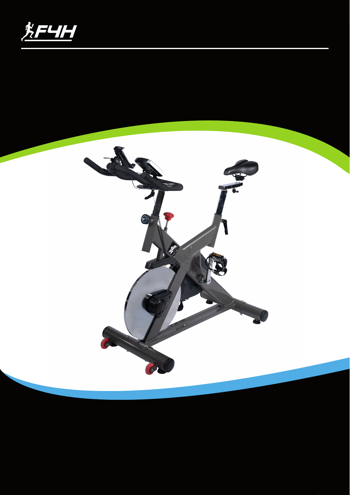
TF-S760 BIKE
USER MANUAL
IMPORTANT - Please Read Instructions Fully Before Assembly Or Use
These instructions contain important information which will help you get the best
from your equipment and ensure safe and correct assembly, use and maintenance.
If you need help or have damaged or missing parts,
call the Customer Helpline: 0330 124 0718 (Opening hours: Mon-Fri 9:00am-3:00pm)
or Email: customerservices@fit4home.co.uk

2
CONTENTS
Safety Information
Exploded Diagram
Accessories List
Assembly Instructions
Step 1
Step 2
Step 3
Step 4
Step 5
Step 6
Operating the Computer
Mobile Phone/ Pad Holder
Exercise Instructions
Declaration
03
04
05
06
07
08
09
10
11
12
13
14
15
16

3
IMPORTANT SAFETY INFORMATION
Please read carefully prior to using this product.
You should consult a physician before beginning any exercise program including a program
involving the use of the spin bike – this is especially important if you are pregnant, sick, injured
or have a pre-existing medical condition. Your doctor’s advice is essential if you are taking
medication that aects your heart rate, blood pressure or cholesterol level. If whilst using the
spin bike you feel dizzy, faint, short of breath, or any pain, STOP using the bike immediately and
consult a physician.
When using tness equipment, you should follow normal safety procedures, especially if there
are children or pets around.
1. Always place the bike at on the ground in a dry clean area, to avoid placing the bike on thick
carpet. For safety, the equipment should have at least 0.5 meter of free space all around it.
2. Adjust the front and back stabilizers each time you use the bike to ensure it’s stable and
level with the oor.
3. In the event the bike malfunctions, PUSH down on the red EMMERGENCY STOP – the bike
will stop immediately – contact the distributor for further instructions.
4. Never exceed the MAX or STOP mark when adjusting the handlebars and saddle, to ensure
the adjustment locks are tight and secure.
5. Spinning pedals can cause injury and damage the bike – to reduce pedal speed, add
resistance by turning the TENSION control.
6. Regular maintenance will prolong the life of your bike and prevent injury – refer to the
Maintenance section below.
7. Always use proper lifting techniques and / or assistance when lifting or moving the bike to
avoid injury.
8. Never leave the bike unattended especially if there are young children around.
9. The Spin bike is not suitable for children under 14 years of age or for people with physical
conditions unless supervised by an adult.
10.The maximum user weight for the belt bike is 150KG.
11.The Spin bike is designed for the use of indoor only, please do not use it in the environment
where it is wet and it’s in the sun.
4
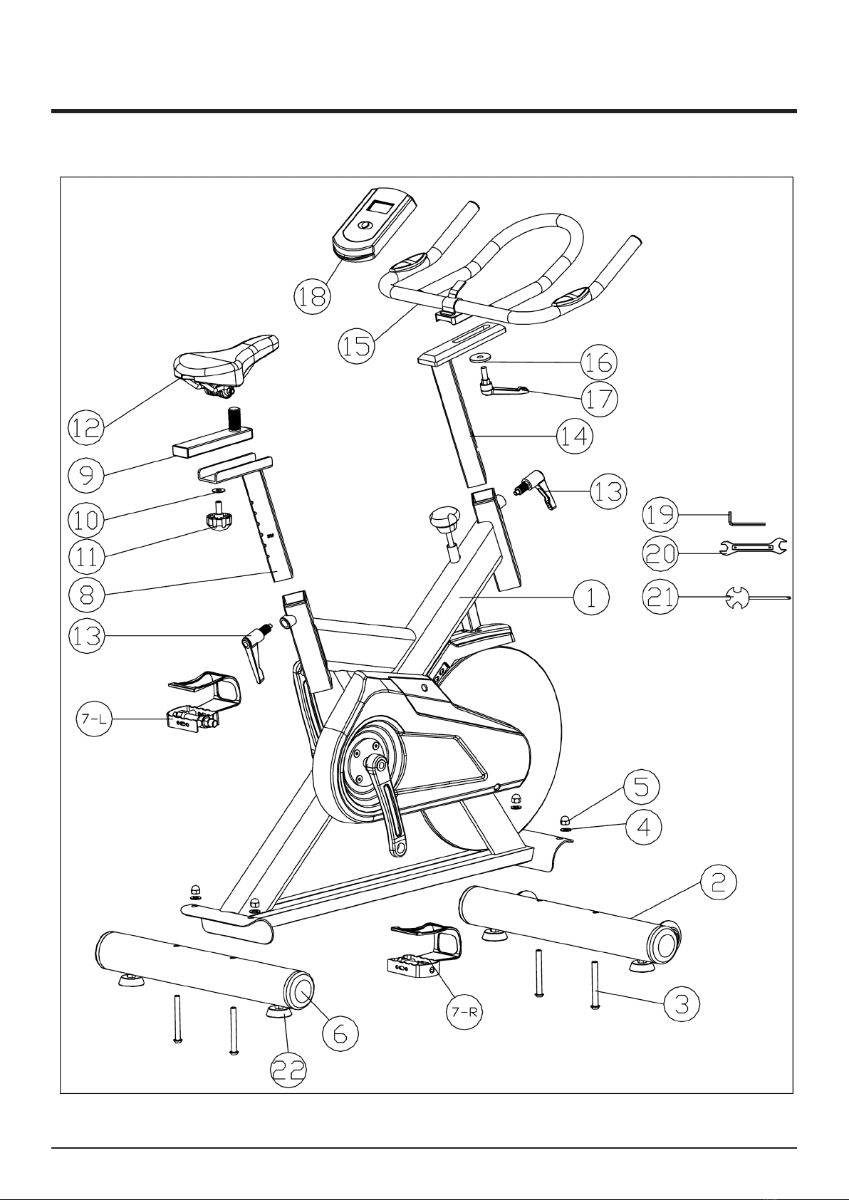
EXPLODED DIAGRAM

5
NO. DISCRIPTION QTY
1 Main frame 1
2 Front stabilizer 1
3 Fixing bolt 4
4 Curved washer 4
5 Cap nut 4
6 Back stabilizer 1
7-L Left pedal 1
7-R Right pedal 1
8 Seat support tube 1
9 Seat slider 1
10 Washer 2
11 Lock knob M10 2
12 Saddle 1
13 L shape lock knob M16 2
14 Handle support tube 1
15 Handlebar 1
16 Flat washer 1
17 L shape lock knob 1
18 Computer 1
19 L shape wrench 1
20 13-15 wrench 1
21 Multi-functional wrench (Screwdriver) 1
22 Foot levelers 4
ACCESSORIES LIST

6
ASSEMBLY INSTRUCTIONS
6 easy steps to assemble then you’re ready to workout – it takes approx
30 mins to assemble.
NOTE:
After taking out the frame (1) from the carton, please remove all the
protection parts of the frame, as
shown in the following gure A, B and C.
1. Turn the lock knob (13) in counterclockwise direction to remove the
protective tube (23) with gure A.
2. Use the L shape wrench (19) to turn the screw (24) in an anticlockwise
to remove the protective pipe with gure B.
3. Turn the frame’s side rst, then remove the screw (27) with the
screwdriver (21), and then turn the ywheel to take out the wood block
(28).
The removed protection parts (23), (24), (25), (26), (27) and (28) are
classied and put into garbage collection bins.

7
ASSEMBLY INSTRUCTIONS
STEP 1
1. Fix the Front Stabilizer (2) to the Main frame (1) using 2 x Fixing bolts (3), 2 x Curved washers
(4) and 2 x Cap Nuts (5) provided.
2. Repeat Step 1. to install the Rear Stabilizer (6) to Main Frame (1).
8
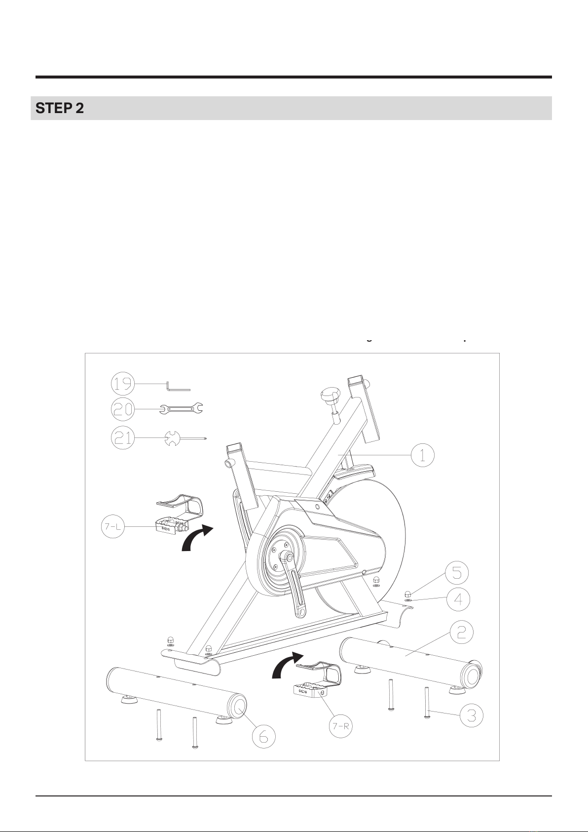
ASSEMBLY INSTRUCTIONS
STEP 2
1. First align the left pedal with the left crank at an angle of 90 degrees (Vertically), then rmly
x the Pedal marked L (7-L) to the crank arm marked L in an anti-clockwise direction until
tight.
2. First align the right pedal with the right crank at an angle of 90 degrees (Vertically), then
rmly x the Pedal marked R (7-R) to the crank arm marked R in a clockwise direction until
tight.
Warm Remarks: Please make sure the pedal thread align with the crank thread, and then screw
in more than 3 circles by hands before using tool to tight. If you feel unsmooth when screwing
by hands, please unscrew the pedals and re-align the pedal thread and crank thread to avoid
thread stripped.
Failure to follow the above instructions could result in damage to the cranks and pedals.

9
ASSEMBLY INSTRUCTIONS
STEP 3
1. Insert the Seat support tube (8) to the rear opening of the Main frame (1) , and adjust the
Seat support tube to your desired height, then ret and tighten the L shape lock knob (13).
2. Attach the Seat slider (9) onto the Seat support tube (8), then select your desired forwarder
to backward position, secure with the Flat washer (10) and M10 Lock Knob (11).
3. Fix the Saddle (12) to the Seat slider (9) with the 13-15 Wrench (20) until tight.
10
ASSEMBLY INSTRUCTIONS
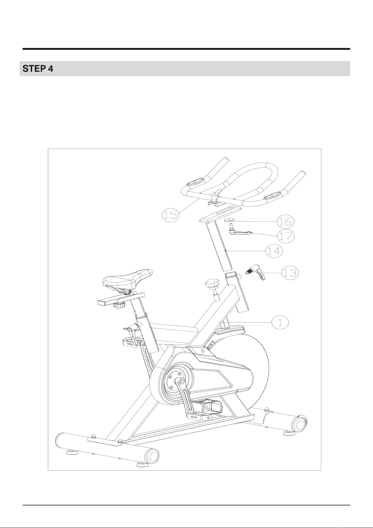
STEP 4
1. Insert the Handle support tube (14) into the front opening tube of the Main frame (1), to
adjust to your desired height, then ret and tighten the M16 Lock knob (13).
2. Attach the Handlebar (15) onto the top of the Handle support tube (14), then select your
desired forwarder to backward position, secure with one Flat washer (16) and the L shape
lock knob (17).

11
ASSEMBLY INSTRUCTIONS
STEP 5
1. Slide the iron bracket welded on the computer into the ute on the back of the Computer
(18). Then remember to load the battery, and insert the sensor wire (1-1) from the Main
frame into the “SENSOR” hole (1-1) on the back of the Computer (18), and insert the pulse
wire from the Handlebar (15) into the “PULSE” hole (15-1) on the back of the computer (18).
2. Attach the Handlebar (15) onto the top of the Handle support tube (14), then select your
desired forwarder to backward position, secure with one Flat washer (10) and the M10 Lock
knob (11).

12
ASSEMBLY INSTRUCTIONS
STEP 6
1. If you feel unsteady while riding, please adjust the 4 foot levelers (22) under the front and
rear stabilizers.
Most Importance:
After all above 6 steps nished, the most important is to make sure all the bolts and parts
aresecurely xed before you are riding on the bike.

13
OPERATIONS GUIDE
1. You will need one AAA battery (provided) to operate the Computer.
2. To select the function you want, press the MODE button and t hen select the function of
choice from the table above.
3. To reset the Computer, hold down the RESET button for 5 seconds.
4. The Computer will automatically turn o after 4 minutes when the bike is not in use. Press
any key to restart.
5. If there is an impro per display on the Computer, please replace one AAA battery with new
one at the same time
REPLACING THE BATTERY
1. Remove the bat tery cover on the back of the computer.
2. Replace 1 x AAA battery
3. If the display is not clear or only partial segments appeared, remove the batter y and wait for
15 seconds before re installing it
4. When the batter y is removed, all the functional values will reset to zero.
COMPUTER OPERATION
SCAN Scans all functions
TIME, SPEED, DISTANCE, TOTAL DIST, PULSE, CALORIES
TIME Displays work out time lapse while exercising
SPEED Displays the current speed
DISTANCE Displays the distance while exercising
TOTAL DIST Displays the total distance at
PULSE Display the current heart rate of the exerciser
CALORIES Displays the calories you have burned

14
MOBILE PHONE/ PAD HOLDER

15
Using your EXERCISE CYCLE will provide you with several benets, it will improve your physical
tness, tone muscle and in conjunction with calorie controlled diet help you lose weight.
1. THE WARM UP PHASE
This stage helps get the blood owing around the body and the muscles working properly. It will
also reduce the risk of cramp and muscle injury. It is advisable to do a few stretching exercises
as shown below. Each stretch should be held for approximately 3 0 seconds, do not force or
jerk your muscles into a stretch if it hurts, STOP.
2. THE EXERCISE PHASE
This is the stage where you put the eort in. After regular use , the muscles in your legs will
become more exible. Work to your own pace but it is very important to maintain a steady
tempo throughout. The rate of work should be sucient to raise your heart beat into the target
zone shown on the graph below.
This stage should last for a minimum of 12 minutes though most people start at about 15 20
minutes.
EXERCISE INSTRUCTIONS

16
EXERCISE INSTRUCTIONS
3. THE COOL DOWN PHASE
This stage is to let your Cardio vascular System and muscles wind down. This is a repeat of the
warm up exercise e.g. reduce your tempo, continue for approximately 5 minutes. The stretching
exercises should now be repeated, again remembering not to force or jerk your muscles into
the stretch. As you get tter you may need to train longer and harder. It is advisable to train at
least three times a week, and if possible space your workouts evenly throughout the week.
4. FAULT FINDER
If you do not receive numbers appearing on your computer, please ensure all connections are
correct.
MUSCLE TONING
To tone muscle while on your exercise cycle you will need to have the resistance set quite high.
This will put more strai n on your leg muscles and may mean you cannot train for as long as you
would like. If you are also trying to improve your tness you need to alter your training program.
You should train as normal during the warm up and cool down phases, but towards the end of
the exercise phase you should increase resistance making your legs work harder. You will have
to reduce your speed to keep your heart rate in the target zone.
WEIGHT LOSS
The important factor here is the amount of eort you put in. The harder and longer you work the
more calories you will burn. Eectively this is the same as if you were training to improve your
tness, the dierence is the goal.
USE
The seat height can be adjusted by removing the adjustment knob and raising or lowering the
seat. There are holes in the seat post allowing for a range of heights. Once the correct height
has been chosen, ret the adjustment knob and tighten. The tension control knob allows you
to alter the resistance of the pedals. A high resistance makes it more dif cult to pedal, a low
resistance makes it easier. For the best results set the tension while the bike is in use.

17
MAINTENANCE
MAINTENANCE
Regular maintenance will prolong the life of your spin bike and prevent injury. We strongly
recommend that you do the following on a regular basis:
1. Clean the bike after use with a soft cloth ensure it is dry. Note, a buildup of moisture over time
will cause corrosion.
2. Clean the Computer display with a soft cloth and anti static computer spray to remove dust
or nger pr ints. Note , harsh chemicals will destroy the protective coating on the Computer and
cause a static build up inside the Computer that could damage the components.
3. Check the front and back stabilizers each time you use the bike to ensure the bike is stable
and level with the oor.
4. Check and tighten loose nuts/buts, the saddle adjustment locks, pedals, and handlebars to
ensure they are secure each time you use the bike to avoid injury.
5. A spe nt battery is hazardous waste, please dispose of it correctly, and do not throw it in the
trash.
6. For replacement parts, please contact us

18
Declaration of Conformity
We, Importer
Fit4home Ltd
Unit A, Perseverance Mills, Olive Lane, Darwen BB3 3DQ United Kingdom
Declare that the product
S760 Racing Bike
Complies with Stationary training equipment Part 10: Exercise bicycles
with a xed wheel or without freewheel,
additional specic safety
ISO 20957 10
Authorised Signatory and technical le holder
Signed for and behalf of:
Fit4home Ltd
Unit A
Perseverance Mills
Olive Lane
Darwen
BB3 3DQ
United Kingdom
Tassadaq Hussain

19
This manual suits for next models
1
Table of contents
Other Fit4Home Exercise Bike manuals

Fit4Home
Fit4Home TF-8938 User manual

Fit4Home
Fit4Home ORIOLE EB-OW-ORIOLEX User manual

Fit4Home
Fit4Home KPR65910 User manual

Fit4Home
Fit4Home F4H-EB-ORB2600S User manual

Fit4Home
Fit4Home ES893 User manual

Fit4Home
Fit4Home TONERX TF-BB8001A User manual

Fit4Home
Fit4Home KPR4890W User manual

Fit4Home
Fit4Home KPR65850 User manual


