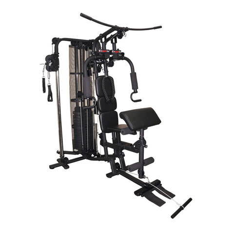
Fit4Home TF-3001C-1 User manual

1
F4H-HG-3001C1
Please Keep For Future Reference
IMPORTANT - Please Read Instructions Fully Before Assembly Or Use
These instructions contain important information which will help you get the best
from your equipment and ensure safe and correct assembly, use and maintenance.
If you need help or have damaged or missing parts,
call the Customer Helpline: 0330 124 0718 (Opening hours: Mon-Fri 9:00am-3:00pm)
or Email: customerservices@fit4home.co.uk
USER MANUAL
TF-3001C-1 HOME GYM

2
CONTENTS
Safety Information
Parts Table
Parts List
Assembly Instructions
Step 1
Step 2
Step 3
Step 4
Step 5
Step 6
Step 7
Step 8
Step 9
Step 10
Step 11
Step 12
Warm Up Routine
Fit4Home Ltd
Declaration
03
04
05,06
08
08
09
10
11
12
13
14
15
16
17
18
19
20,21
22
23

3
PRECAUTIONS
BE SURE TO READ THE ENTIRE MANUAL BEFORE YOU ASSEMBLE OR
OPERATE YOUR MACHINE. IN PARTICULAR, NOTE THE FOLLOWING
SAFETY PRECAUTIONS:
1. It is important to read this entire manual before assembling and using the equipment. Safe
and eective use can only be achieved if the equipment is assembled, maintained and used
properly. It is your responsibility to ensure that all users of the equipment are informed of all
warnings and precautions.
2. Before starting any exercise program you should consult your doctor to determine if you have
any medical or physical conditions that could put your health and safety at risk, or prevent
you from using the equipment properly. Your doctor’s advice is essential if you are taking
medication that aects your heart rate, blood pressure or cholesterol level.
3. Be aware of your body’s signals. Incorrect or excessive exercise can damage your health.
Stop exercising if you experience any of the following symptoms: pain, tightness in your
chest, irregular heartbeat, and extreme shortness of breath, light headedness, dizziness or
feelings of nausea. If you do experience any of these conditions you should consult your
doctor before continuing with your exercise program.
4. Keep children and pets away from the equipment. The equipment is designed for adult use
only.
5. Use the equipment on a solid, at level surface with a protective cover for your oor or
carpet. To ensure safety, the equipment should have at least 2 meters of free space all
around it.
6. Before using the equipment, check that the nuts and bolts are securely tightened.
7. The safety of the equipment can only be maintained if it is regularly examined for damage
and/or wear and tear.
8. Warning the equipment must be installed on a stable base and properly leveled oor. Always
use the equipment as indicated. If you nd any defective components while assembling or
checking the equipment, or if you hear any unusual noises coming from the equipment during
use, stop immediately. Do not use the equipment until the problem has been rectied.
9. Wear suitable clothing while using the equipment. Avoid wearing loose clothing that may get
caught in the equipment or that may restrict or prevent movement.
10.Care must be taken when lifting or moving the equipment so as not to injure your back.
Always use proper lifting techniques and / or seek assistance if necessary. Regular checking
of the integrity of guards and safety devices.
11.Parents and those in charge of children should be aware of their responsibility around this
equipment. The natural play instinct and fondness for experimenting of children can lead to
situations and use of the training equipment for which it is not intended.
IMPORTANT SAFETY INFORMATION

4
IMPORTANT SAFETY INFORMATION
12.If children are allowed to use the equipment their mental and physical development and
above all their temperament should be taken in to account. They should be supervised and
instructed to the correct use of the equipment. The equipment is under no circumstances
suitable as a child’s toy.
13.All moveable accessories (e.g. arms, bolts and nuts, etc.) require weekly maintenance. Check
them before use every time. If anything broken or loose, please x them immediately. You
may continue using after they return to good conditions.
14.Special attention to components most susceptible to wear.
15.The equipment is not suitable for therapeutic use.
16.The equipment is suitable for home use only. Maximum weight of user: 110kg
WARNING: BEFORE BEGINNING ANY EXERCISE PROGRAM, CONSULT
YOUR PHYSICIAN. THIS IS ESPECIALLY IMPORTANT FOR INDIVIDUALS
OVER THE AGE OF 35 OR PERSONS WITH PRE-EXISTING HEALTH
PROBLEMS. READ ALL INSTRUCTIONS BEFORE USING ANY FITNESS
EQUIPMENT.
SAVE THESE INSTRUCTIONS / Maximum user’s weight: 110 KG

5
EXPLODED DIAGRAM

6
PARTS LIST
NO. DESCRIPTION Q’TY NO. DESCRIPTION Q’TY
1 Main Frame 1 53 Pulling Cable Wire 1
2 Base Module 1 54 Pushing Cable Wire 1
3 Slope Beam 1 55 Swing Leg Cable Wire 1
4 Rear Button Tuber 1 56 Chain 1
5 Rear Post 1 57 Hooks 5
6 Saddle Module 1 58 Chain 1
7 Saddle Adjustable Anchor 1 59 Hex Bolt (M10*35) 2
8 Saddle Adjusting Bracket 1 60 Hex Bolt (M10*50) 12
9 Saddle 1 61 Hex Bolt (M10*65) 10
10 Leg Swing Module 1 62 Hex Bolt (M10*70) 22
11 Pushing Knob 1 63 Hex Bolt (M10*130) 1
12 Left Bar Swinging Bracket 1 64 Hex Bolt (M8*15) 4
13 Right Bar Swinging Bracket 1 65 Hex Bolt (M8*60) 4
14 Foam 4 66 Hex Bolt (M12*85) 1
15 Foam Tube(1( 1 67 Washer (φ8) 14
16 Foam Tube(2( 1 68 Washer (φ10) 96
17 Back Cushion Adjusting
Anchor
1 69 Washer (φ12) 2
18 Back Cushion Adjusting
Bracket
1 70 Washer (φ37×φ12.5×2.5) 2
19 Back Cushion 1 71 Nylon Nut M10 44
20 Pulley Bracket 1 72 Nylon Nut M12 3
21 Tumbler Adjusting Bracket 1 73 Cushion 2
22 Guide Plate Module 2 74 Cushion 1
23 Left Guide Plate Module 1 75 Cushion 1
24 Right Guide Plate Module 1 76 Alloy Knot 2
25 Arms Cushion 2 77 Alloy Knot 6

7
PARTS LIST
26 Long Lever 1 78 Alloy Knot 4
27 Short Lever 1 79 Plastic
Spacerφ22×φ10.5×17
2
28 Slide Tube Module 1 80 □45 Square Cap 2
29 Protective Cover 2 81 □50 Square Cap 15
30 Slide Pole 2 82 □60*30 Square Cap 2
31 Pull Pole 1 83 □50 Square Cap 2
32 Pedal 1 84 Single Handle bar 1
33 Adjustable Pulley Unit 2 85 Double handle bar 1
34 Adjustable Pulley Unit 1 86 φ25 Round Cap 8
35 Junction Plate(1) 3 87 φ32 Round Cap 2
36 Junction Plate(2( 3 88 Plastic Bushing 6
37 Sandbag Hook 1 89 Foam Grip 4
38 Junction Plate(3( 1 90 Foam Grip 2
39 Pulley Cover 26 91 Down Bracket 1
40 Pulley 17 92 Sandbag Bracket 1
41 Cushion 4 93 Speed Ball Bracket 1
42 End Cap 7 94 Sandbag Subassembly 1
43 End Cap 2 95 Speed Ball 1
44 Double Head Bolt 1 96 Speed Ball Bae 1
45 Weight Block 9 97 Hex Bolt(M10*115( 1
46 L-Shape Bolt 1 98 Sandbag Anchor 1
47 Guide Block 1 99 Hex Bolt M8 1
48 Bolt 2 100 Alloy Knot 2
49 Ball Hoodle Knob 1 101 Small End Cap 2
50 Pop-pip Knob 2 102 Hex Bolt (M8*20) 4
51 Connected Bolt 1 103 Hex Bolt (M10*25) 2
52 Swing Arm Cable Wire 1 104 Hex Bolt (M8*70) 2

8
ASSEMBLY INSTRUCTIONS
STEP 1
1. Fix the rear Button Tube (4) and Button Post (5) onto Base Module (2) with Hex Bolt(62) and
Washer(68) and Nylon Nut(71).
2. Lock the Main Frame (1) onto Base Module (2) with Hex Bolt (62) and Washer (68) and Nylon
Nut.(71).
3. Assemble the Slope Beam(3) onto Main Frame(1) with Hex Bolt(62) and Washer(68) and Nylon
Nut.(71) and Junction Plate(38).Then x the Rear Post(5) onto Slope Beam(3) with Hex Bolt
(61) and Washer(68) and Nylon Nut.(71) and Junction Plate(35).
4. Insert the Pedal (32) to the Base Module (2) with Hex Bolt(61) and Washer(68) and Nylon Nut.
(71).

9
ASSEMBLY INSTRUCTIONS
STEP 2
1. Fix the Down Bracket (91) onto Base Module (2) with Hex Bolt (61) and Washer (68) and Nylon
Nut.(71).
2. Put the Slider Pole (30) into the orice of Base Module (2) and insert the Washer (41) and
Weight Blocks(45) and Guide Block (47)and Pull Pole(31) into Slide Pole(30).(Note: Keep the
hole of Pull Pole and the hole of Safety Pin in the same direction).Last, put the L Shape Bolt
(46) into any hole of Weight Blocks (45) and Pull Pole (31).
3. Firstly lock the Slide Tube Module(28) onto Slide Pole(30) with Hex Bolt(61) and Washer(68)
and Nylon Nut.(71).Secondly assemble the Speed ball Bracket(93) and Slide Tube Module(28)
with Hex Bolt(103) and Washer(68). lastly Fix the Speed ball Bracket(93) and Sandbag
Bracket(92) onto Slope Beam(3) with Hex Bolt(62) Hex Bolt (97) and Washer(68) and Nylon
Nut(71).

10
ASSEMBLY INSTRUCTIONS
STEP 3
1. Fix the Pulley Bracket Tumbler (20) and Adjusting Bracket (21) onto the Main Frame (1) with
Hex Bolt(62) and Washer(68) and Nylon Nut(71).
2. Fix the Guide Plate Modules(23)(24) onto Tumbler Adjusting Bracket(21) with Nylon Nut (72)
and Washer (70)
Note: Keep the Guide Plate Modules (23)(24) can turning freely and put on the end caps(43).
3. Lock the Washer(25) onto Guide Plate Modules(23)(24) with Hex Bolt(65) and Washer(67).
4. Insert the Bolt(48) into Guide Plate Modules(23)(24) tightly.

11
ASSEMBLY INSTRUCTIONS
STEP 4
1. Fix the Back Cushion Adjusting Anchor (17) onto the Main Frame (1) with Hex Bolt(62) and
Washer(68) and Junction Plate(36) and Nylon Nut(71).
2. Lock the Saddle Module (6) onto the Main Frame (1) with Hex Bolt(62) and Washer(68) and
Junction Plate(36) and Nylon Nut(71).
3. Fix the Saddle Adjustable Anchor (7) onto Saddle Module (6) with Hex Bolt(62) and Washer(68)
and Junction Plate(36) and Nylon Nut(71).
4. Ensure the Saddle (9) x tightly on the Saddle Adjusting Bracket(8) with Hex Bolt(64) and
Washer(67).
5. Fix the Back Cushion(19) into the Back Cushion Adjusting Bracket(18) with Hex Bolt(64) and
Washer(67).
6. Insert the Saddle Adjusting Bracket (8) and the Back Cushion Adjusting Bracket (18) into the
Saddle Adjustable Anchor(7) and Back Cushion Adjustable Bracket(17). Tie the Pop-pip Knob
(50) after adjusting the property position and aiming at the right hole.
7. Put the Foam Tube (15) into Saddle Module(6) and then cover with Foam(14).

12
ASSEMBLY INSTRUCTIONS
STEP 5
1. Lock the Bar Swinging Bracket(12)(13) into Saddle Module(2) with Nylon Nut(71) and
Washer(68) and Double Head Bolt(44).Ensure both Bar Swing Brackets(12)(13) can turning
freely.
2. Insert the Pushing Knob(11) into Saddle Module(2) and lock the Pushing Knob(11) onto both
Bar Swinging Bracket(12)(13) with Hex Bolt(61)(62) and Washer(68) and Junction Plate(35)
and Nylon Nut(71).
3. First, Fix the Leg Swing Module(10) onto the Saddle Module(6) with Hex Bolt(66) and
Washer(69) and Nylon Nut(72).Second, Insert the Foam Tube(16) into the Leg Swing
Module(10).Put on Foam (14).Last, Fix Ball Hoodle Knob(49) onto Saddle Module(6). Make
sure the Ball Hoodle Knob(49) can be pull out when using the Leg Swing Module(10).

13
ASSEMBLY INSTRUCTIONS
STEP 6
1. Fix the Swing Arm Cable Wire (52) onto the U shape slot of Guide Plate Module(22) with Hex
Bolt(59) and Washer(68) and Nylon Nut(71).As show in g. Then put the Swing Arm Cable
Wire(52) though pulley(40), and lock the pulley(40) onto Adjustable Pulley Unit(33) and Pulley
Bracket (20) with Hex Bolt(60) and Washer(68) and Pulley Cover(39) and Nylon Nut(71).
Note: After assembly. Try the both Guide Plate Module (23)(24) moving freely. And Swing
Arm Cable Wire (52) though pulley(40) also moving smoothly as Guide Plate Module(23)(24)
turning. No rocked.

14
ASSEMBLY INSTRUCTIONS
STEP 7
1. Put the Pulling Cable Wire(53) though Slope Beam(3) and Pulley(40). Then lock the Pulley(40)
onto Slop Beam(3) and Slide Tube Module (28) and Adjustable Pulley Unit(34) with Hex
Bolt(61)(60) and Pulley Cover(39) and Nylon Nut(71).
2. Insert the bolt of Pulling Cable Wire(53) into Connected Bolt(51).Then lock the Connected
Bolt (51) into Pull Pole (31).
3. First connect the Long Lever(26) with Chain(56) using Hook(57).Second use the Hook (57) to
link Single Pull bar (84) to Long Lever (53).As show in g. Last, Put the Long lever(26) on the
Slop Beam(3).

15
ASSEMBLY INSTRUCTIONS
STEP 8
1. Insert the bolt of Swing Leg Cable Wire(55) into the Adjustable Pulley Unit(33) .Then use the
Hex Bolt(60)(61),Washer(68),Pulley Cover(39) and Nylon Nut(71)to x the pulleys(40) to the
Adjustable Pulley Unit(33)(34),Base Module(2) and Leg Swing Module(10) tightly. As show
bellow.
Note: Make sure that Swing Leg Cable Wire can move smoothly.
2. Use the Hook(57) to connect well the Short Lever(27) with Chain(58).Linking to the end of the
Swing Leg Cable Wire (55) with Hook(57).

16
ASSEMBLY INSTRUCTIONS
STEP 9
1. Insert the bolt of Pushing Cable Wire(54) into Adjustable Pulley Unit(33),then use Hex Bolt(60)
(62)(63), Washer(68),Pulley Cover(39),Plastic Spacers(79)(88) and Nylon Nut(71) to lock the
pulleys(40) onto Base Module(2), Main Frame(1) and Pushing Knob (11) distinguish. Note:
Ensure the Pushing Cable Wire (54) can move smoothly.
2. As show of the picture A.. Connect the Double handle bar (85) to the end of Pushing Cable
Wire(54) with Hook(57).

17
ASSEMBLY INSTRUCTIONS
STEP 10
1. Lock the Protective Cover(29) into Slide Tube Module (28) and Base Module(2) with Hex
Bolt(102) and Washer(67).

18
ASSEMBLY INSTRUCTIONS
STEP 11
1. Fix the Speed Ball Bae(96) into Speed Ball Bracket(93) with Hex Bolt(104), Washer(67).
2. Assemble the Speed Ball (95) on the Speed Ball Bae (96).
3. Using the Nylon Nut (99), Washer (67), Alloy Knot (100) and Hex Bolt(99) to x the Sandbag
Hook(37) on the Sandbag Bracket(92). Then x the Sandbag Anchor(98)
4. to the Down bracket(91)
5. Connect the chain of sandbag (94) to Sandbag Hook (37).then connect the hook on the lower
end of the sandbag(94) to the Sandbag Anchor(98)

19
ASSEMBLY INSTRUCTIONS
STEP 12
1. When you nishing assembling. Make sure the lines of Swing Arm Cable Wire (52), Pulling
Cable Wire (53), Pushing Cable Wire (54) and Swing Leg Cable Wire (55) correct connect as
the directions of following g.

20
WARM UP AND COOL DOWN ROUTINE
Using your AB TOWER will provide you with several benets, it will improve your physical tness, tone
muscle and in conjunction with a calorie controlled diet help you lose weight. The WARM-UP is an
important part of any workout. The purpose of warming up is to prepare your body for exercise and to
minimize injuries. Warm up for two to ve minutes before aerobic exercising.It should begin every session
to prepare your body for more strenuous exercise by heating up and stretching your muscles, increasing
your circulation and pulse rate, and delivering more oxygen to your muscles.
COOL DOWN at the end of your workout, repeat these exercises to reduce soreness in tired muscles. The
purpose of cooling down is to return the body to its resting state at the end of each exercise session. A
proper cool-down slowly lowers your heart rate and allows blood to return to the heart.
HEAD ROLLS
Rotate your head to the right for one count,
you should feel a stretching sensation up the
left side of your neck. Then rotate your head
back for one count, stretching your chin to the
ceiling and letting your mouth open. Rotate
your head to the left for one count, then drop
your head to your chest for one count.
SHOULDER LIFTS
Lift your right shoulder toward your ear for one
count. Then lift your left shoulder up for one
count as you lower your right shoulder.
SIDE STRETCHES
Open your arms to the side and lift them until
they are over your head. Reach your right arm
as far toward the ceiling as you can for one
count. Repeat this action with your left arm.
This manual suits for next models
1
Table of contents
Other Fit4Home Home Gym manuals

Fit4Home
Fit4Home POWER TOWER TF-1007 User manual

Fit4Home
Fit4Home TF-1001A-1 User manual

Fit4Home
Fit4Home TF-7005A User manual
Fit4Home
Fit4Home ELITE GAIN TF-7005 User manual

Fit4Home
Fit4Home KPR91100 User manual

Fit4Home
Fit4Home TF-7080A User manual
Fit4Home
Fit4Home TF-7002 MULTIGYM User manual

Fit4Home
Fit4Home TF-7001 User manual
Fit4Home
Fit4Home TF-7509 User manual
Popular Home Gym manuals by other brands

Vicore Fitness
Vicore Fitness CORE AB owner's manual
Weider
Weider 8920 user manual

Sunny Health & Fitness
Sunny Health & Fitness SF-RW5854 user manual

First Degree Fitness
First Degree Fitness Titan Rower AR owner's manual
AsVIVA
AsVIVA RA6 O Series manual
True & Paramount
True & Paramount XFT-100 Assembly manual
