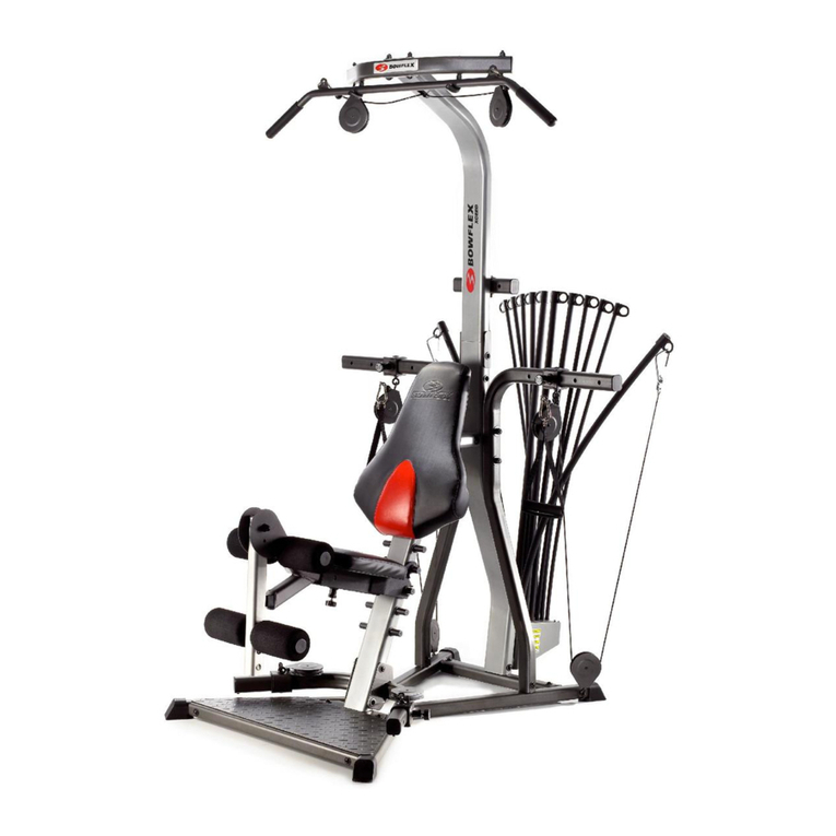
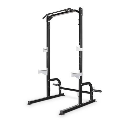
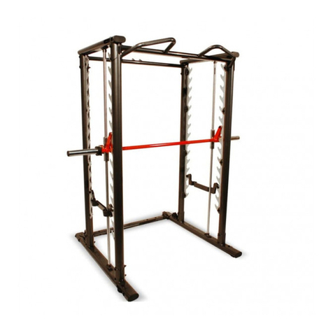
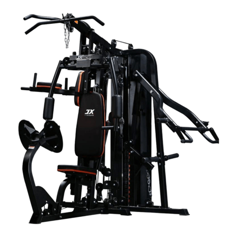
Fit4Home TF-7080A User manual

1
HJ-R2P7-PGFJPlease Keep For Future Reference
IMPORTANT - Please Read Instructions Fully Before Assembly Or Use
These instructions contain important information which will help you get the best
from your equipment and ensure safe and correct assembly, use and maintenance.
If you need help or have damaged or missing parts,
call the Customer Helpline: 0330 124 0718 (Opening hours: Mon-Fri 9:00am-3:00pm)
or Email: customerservices@fit4home.co.uk
SUPERGAIN TF-7080A
USER MANUAL

2
CONTENTS
Safety Information
Strength Programme
Exercise Guidelines
Parts Chart
Parts List
Assembly Instructions
Step 1
Step 2
Step 3
Step 4
Step 5
Step 6
Step 7
Step 8
Step 9
Step 10
Step 11
Exercises
Maintenance
Declaration
03, 04
05
06
07,08
09
10
10
11
12
13
14
15
16-17
18
19
20
21
22
23
24

3
IMPORTANT SAFETY INFORMATION
Home Gym 7080A
Please note the following information given:
Whilst checking the parts list pay attention to the frame, due to some
parts having already been added to the frame.
Some screw bolts, washers and nuts may have already been added to the
frame.
POSSIBLE: In the manual it may state that there are 5 clip hooks (C9), but
in reality, it will may come 8.
If you need help or have damaged or missing parts, call the Customer
Helpline: 03301240718
Telephone Line Opening Hours: Mon – Fri: 9:00 am – 3:00 pm
Fit4home Ltd
Unit A, Perseverance Business park, Olive Lane
Darwen, BB3 3DQ

4
IMPORTANT SAFETY INFORMATION
This exercise equipment is built for optimum safety. However, certain precautions apply
whenever you operate a piece of exercise equipment. Be sure to read the entire manual before
you assemble or operate your equipment. In particular, note the following safety precautions:
1. Keep children and pets away from the equipment at all times. DO NOT leave children
unattended in the same room with the equipment.
2. Only one person at a time should use the equipment.
3. If the user experiences dizziness, nausea, chest pain, or any other abnormal symptoms,
STOP the workout at once. CONSULT A PHYSICIAN IMMEDIATELY.
4. Position the equipment on a clear, leveled surface. DO NOT use the equipment near water or
outdoors.
5. Keep hands away from all moving parts.
6. Always wear appropriate workout clothing when exercising. DO NOT wear robes or other
clothing that could become caught in the equipment. Running or aerobic shoes are also
required when using the equipment.
7. Use the equipment only for its intended use as described in this manual. DO NOT use
attachments not recommended by the manufacturer.
8. Do not place any sharp object around the equipment.
9. Disabled person should not use the equipment.
10. Before using the equipment to exercise, always do stretching exercises to properly warm up.
11. Never operate the equipment if the equipment is not functioning properly.
12. A spotter is recommended during exercise.
13. This equipment is designed and intended for home and consumer use only, not for
commercial use.
WARNING: BEFORE BEGINNING ANY EXERCISE PROGRAM, CONSULT YOUR PHYSICIAN.
THIS IS ESPECIALLY IMPORTANT FOR INDIVIDUALS OVER THE AGE OF 35 OR PERSONS
WITH PRE-EXISTING HEALTH PROBLEMS. READ ALL INSTRUCTIONS BEFORE USING
ANY FITNESS EQUIPMENT. TUNTURI FITNESS BV. ASSUMES NO RESPONSIBILITY FOR
PERSONAL INJURY OR PROPERTY DAMAGE SUSTAINED BY OR THROUGH THE USE OF
THIS PRODUCT.
SAVE THESE INSTRUCTIONS.

5
STRENGTH BUILDING PROGRAMME
BEGINNING A STRENGTH BUILDING PROGRAMME
Warming Up
To begin strength training, it is important to stretch and perform light exercise for 5 to 10
minutes. This helps prepare the body for more strenuous exercise by increasing circulation,
raising your body temperature and developing more oxygen to your muscles.
Workout
Each workout to keep in mind that muscle soreness that lasts for a long period in not desirable
and may mean that injury has occurred.
Cool Down
At the end of each workout, perform slow stretching exercises for 5 to 10 minutes. Ease into
each stretch only going as far as you can. This stage allows your muscles wind down after
training.
To provide a total workout program it is also recommended that 2 to 3 days of aerobic exercise is
performed in addition to the strength training.
Drinking Water
For the body to function properly, it must be properly hydrated. If you are exercising, you should
increase your uid intake. The reason for this is that the water you take in will leave your system
through the sweating mechanism that cools your body during exercise. The water you lose
through exercise must be replaced so that the muscles can recover properly.
Rest Day
Although you may not feel like doing it, taking a rest day at least once a week is important
because it gives you body a chance to heal it self. Continuously working your muscle will result in
over training which will not benet in the long run.

6
EXERCISE GUIDELINES
Building Muscle and Gaining Weight
Unlike aerobic exercise, which emphasizes endurance training, anaerobic exercise focuses
on strength training. A gradual weight gain can occur while building the size and strength of
muscles. While developing muscle mass, your body adapts to the stress placed upon it. You can
modify your diet to include foods such as meat, sh and vegetables. These foods help muscles
recover and replenish important nutrients after a strenuous workout.
Muscle Strength and Endurance
To achieve the greatest benet from exercise, it is important to develop an exercise program that
allows you to work all of the major muscle groups equally.
To increase muscles strength; follow this principle:
Increasing resistance and maintaining the number of repetitions of an exercise results in
increased muscle strength.
To tone your body, follow the principle: Decreasing resistance plus increasing the number of
repetitions of an exercise results in increased body tone.
Once you feel comfortable with an exercise, you can change the resistance, the number of
repetitions, or the speed at which you do the exercise. It is not necessary to change all three
variables. For example, let’s say that you are training at 22kgs and performing the exercise
10 times in 3 minutes. When this becomes too easy, you may decide to move up lifting 27kgs
for the same number of repetitions in the same amount of time. Lifting more weights fewer
times most often develops muscle strength. To gain both muscle strength and endurance, it is
recommended that you perform each exercise 15 to 20 reps per set.
Training Intensity
How hard you begin to train depends on your overall level of tness. The soreness you
experienced can be lessened by decreasing the load you place on your muscles and by
performing fewer sets. To avoid injury, you should gradually work into an exercise program
and set the load to your individual tness level. The load should increase as your tness level
increases.
Muscle soreness is common, especially when you rst start exercising. If you are painfully sore
for a long time, it may be time to change your program. Eventually, your muscle system will
become accustomed to the stress and strain placed on it

7
PARTS CHART
NEEDS DIAGRAM IMAGE

8
PARTS CHART

9
PARTS LIST
NO. Description Qty NO. Description Qty
A1 Anterior basal canal 1 A2 Vertical support pipe 1
A3 Posterior basal canal 1 A4 SEAT TUBE 1
A5 Guide rod 2 A6 Weight Selection Tube 1
A7 Main support tube 1 A8 Top support pipe 1
A9 Elbow cushion support tube 1 A10 Kicking pipe 1
A11 Buttery arm bracket 1 A12 Right buttery arm 1
A13 Left buttery arm 1 A14 Handle 2
A15 Upper transverse tie rod 1 A16 Low horizontal tie rod 1
A17 Protective net cover 1 A18 Collodion iron pipe 2
B1 ∅16 Double-headed bolt 1 B2 ∅12 Double-headed bol 2
B3 M12X80mm screw bolt 1 B4 M10X80mm screw bolt 7
B5 M10X75mm carriage bolt 4 B6 M10X60mm screw bolt 2
B7 M10X45mm screw bolt 1 B8 M10X40mm screw bolt 9
B9 M8X20mm screw bolt 12 B10 M8X15mm screw bolt 18
B11 ∅12 washer 8 B12 Ø10 Washer 24
B13 ∅10 Arc washer 8 B14 Ø8 Washer 18
B15 ∅8 Arc washer 10 B16 M12 Nut 7
B17 M10 Nut 26 B18 M8 Nut 2
B19 ∅12 Large washer 1 B20 Knob nut 1
B21 Knob bolt 1 B22 M10X70mm screw bolt 1
C1 Selector pin 1 C2 Fixed pin 1
C3 METAL BUSHING 2 C4 METAL BUSHING 4
C5 Back cushion bracket 4 C6 Single pulley bracket 2
C7 Double pulley bracket 1 C8 Pulley bracket 2
C9 A hook 5 C10 chain 2
C11 Protective mesh cover
bracket
4
D1 Positioning sleeve 1 D2 RUBBER RING 2
D3 pulley 11 D4 pulley 1
D5 Pulley cover 2 D6 Big Sponge 2
D7 Small sponge 4 D8 Weight block topping 1
D9 Counterweight tablet 9 D10 Back cushion 1
D11 SEAT CUSHION 1 D12 Elbow pad 1
D13 Upper wire rope 1 D14 Buttery arm wire rope 1
D15 Bottom wire rope 1 D16 Short bushing 2
D17 Long bushing 2

10
ASSEMBLY INSTRUCTIONS
STEP 1
1. Connect the seat cushion tube (A4) to the rear bottom tube (A3), and use the carriage bolt
(B5) washer (B13) and nut (B17).
2. Connect the vertical support tube (A2) to the seat cushion tube (A4) using bolt (B4) washer
(B12) and nut (B17).
3. Connect straight bottom pipe (A1) to vertical support pipe (A2) using carriage bolt (B5)
washer (B13) and nut (B17).
NEEDS DIAGRAM IMAGE

11
ASSEMBLY INSTRUCTIONS
STEP 2
1. Connect the bracket bottom pipe (A3) using washer (B14).
2. Insert the guide rod (A5) through the rubber ring (D2) into the two holes of the rear bottom
pipe (A3) and then x it with bolts (B9) and washer (B15) from the bottom.
3. Place the weight plate (D9) in the guide rod (A5), (pay attention to personal safety).
4. Place the positioning sleeve (D1) on the weight selection tube (A6) and x it with the xed pin
(C2) then place the weight block top piece (D8) above the weight selection tube (A6).
5. Insert the selector pin (C1) through the heavy block (D9) into the hole of the weight selection
tube (A6).
NEEDS DIAGRAM IMAGE

12
ASSEMBLY INSTRUCTIONS
STEP 3
1. Connect the main support tube (A7) to the seat cushion pipe (A4) and use bolt (B4) washer
(B12) and nut (B17).
2. Install the single pulley bracket (C6) on the main support tube (A7) and x it with bolt (B6)
washer (B12) and nut (B17).
NEEDS DIAGRAM IMAGE

13
ASSEMBLY INSTRUCTIONS
STEP 4
1. Place the guide rod (A5) in the top support pipe (A8) and x it with bolts (B9) and washer (B15).
2. Connect top support pipe (A8) to main support tube (A7) using bolt (B4) washer (B12) and nut
(B17).
3. Connect the bracket (C11) to the top support pipe (A8) using bolts (B10) and washers (B14).
NEEDS DIAGRAM IMAGE

14
ASSEMBLY INSTRUCTIONS
STEP 5
1. Place the metal bushing (C3) in the holes on both sides of the top support tube (A8), then
connect the buttery arm bracket (A11) to the top support tube (A8), and x it with the double
head bolt (B1) washer (B11) and nut (B16).
2. Place the metal bushing (C4) in the upper and lower holes of the right buttery arm (A12),
then connect the right buttery arm (A12) to the right side of the buttery arm bracket (A11),
and x it with a double-head bolt (B2) washer (B11) and a nut (B16).
3. Put the sponge (D6) into the right buttery arm (A12) and adjust it to a certain position.
4. Connect the handle (A14) to the right buttery arm (A12) and x it with bolts (B9) and arc
washers (B15).
5. The same method for assembling the left buttery arm (A13)
NEEDS DIAGRAM IMAGE

15
ASSEMBLY INSTRUCTIONS
STEP 6
1. Insert the elbow cushion support tube (A9) into the cushion tube (A4) and x it with the knob
bolt (B21).
2. Install sponge iron tube (A18) on seat cushion tube (A4) and insert small sponge (D7) from
both sides.
3. Insert a sponge iron tube (A18) on the kick tube (A10). Then insert a small sponge (D7) from
both sides.
NEEDS DIAGRAM IMAGE

16
ASSEMBLY INSTRUCTIONS
STEP 7
1. Connect back cushion bracket (C5) to back cushion (D10), x it with bolt (B10) and washer
(B14),then insert it into the hole on main support tube (A7), and x it with washer (B13) and nut
(B17).
2. Connect the seat cushion (D11) to the seat tube (A4) and x it with bolts (B10) and washers
(B14).
3. Connect the elbow pad (D12) to the elbow cushion support tube (A9) and x it with bolts
(B10) and washers (B14).
NEEDS DIAGRAM IMAGE

17
ASSEMBLY INSTRUCTIONS

18
ASSEMBLY INSTRUCTIONS
STEP 8
1. Put the upper wire rope (D13) through the rst pulley frame of the top support pipe (A8),put
the pulley (D4) and the pulley cover (D5), and x it with bolts (B8) and nuts (B17).
2. Connect the upper wire rope (D13) through the main support pipe (A7) to the second pulley
frame of the top support pipe (A8),place the pulley (D4), and x it with bolts (D8) and nuts
(B17).
3. The upper wire rope (D13) is lowered and bypassed the pulley (D3), then the pulley (D3) is
connected to the pulley bracket (C8) and xed with bolts (D8) and nuts (B17).
4. The upper wire rope (D13) is pulled up and wound around the pulley (D3),connected to the
third pulley frame of the top support pipe (A8), and xed with bolts (B8) and nuts (B17).
5. Draw the upper wire rope (D13) down between the two guide rods (A5), pass through the
large washer (B19), and x it on the weight selection tube (A6).

19
ASSEMBLY INSTRUCTIONS
STEP 9
1. Connect one end of the buttery arm wire rope (D14) to the hook of the left buttery arm
(A12) and x it with bolts (B9) and nuts (B18).
2. The buttery arm wire rope (D14) is wound around the pulley (D3), then the pulley (D3) is
connected to the single pulley bracket (C6) on the left side of the main support tube (A7) and
xed with bolts (B8) and nuts (B17).
3. The buttery arm wire rope (D14) is pulled down and wound around the pulley (D3),then the
pulley is connected to the double pulley bracket (C7) and xed with bolts (B8) and nuts (B17).
4. Installation steps are the same as 2-2 .
5. Installation steps are the same as 2-1.
NEEDS DIAGRAM IMAGE

20
ASSEMBLY INSTRUCTIONS
STEP 10
1. Put the bottom wire rope (D15) through the kick pipe (A10), put the short bushing (D16) into
the holes on both sides of the kick pipe (A10),then put the pulley (D3), and x it with bolt (B22)
washer (B12) and nut (B17).
2. The bottom wire rope (D15) is passed through the opening space at the lower part of the
vertical support pipe (A2), and the bottom wire rope (D15) is pulled up and wound around the
pulley (D3) through the rear opening space of the seat cushion pipe (A4). Then put the long
bushing (D17) into the holes on both sides of the seat tube (A4), insert the pulley (D3), and x
it with bolt (B4) washer (B12) long bushing (D17) and nut (B17).
3. Pull the bottom wire rope (D15) up and around the pulley (D3), connect the pulley (D3) to the
double pulley bracket (C7),and x it with bolts (B8) and nuts (B17).
4. Draw down the bottom wire rope (D15) and wrap it around the pulley (D3). Connect the pulley
(D3) to the pulley frame of the seat tube (A4). Fix it with bolts (B8) and nuts (B17).
5. Pull the bottom wire rope (D15) up and around the pulley (D3), connect the pulley (D3) to the
pulley bracket (C8),and x it with bolts (B8) and nuts (B17).
6. Draw down the bottom wire rope (D15) and connect it with chain (C10) and hook (C9) on the
posterior basal canal (A3)
.
Note: adjust the wire rope (D15) to enough and x the chain position with hook
NEEDS DIAGRAM IMAGE
This manual suits for next models
1
Table of contents
Other Fit4Home Home Gym manuals

Fit4Home
Fit4Home TF-7001 User manual

Fit4Home
Fit4Home TF-1001A-1 User manual

Fit4Home
Fit4Home POWER TOWER TF-1007 User manual

Fit4Home
Fit4Home TF-7005A User manual
Fit4Home
Fit4Home TF-7002 MULTIGYM User manual

Fit4Home
Fit4Home TF-3001C-1 User manual
Fit4Home
Fit4Home ELITE GAIN TF-7005 User manual
Fit4Home
Fit4Home TF-7509 User manual

Fit4Home
Fit4Home KPR91100 User manual


