Edwards WRH gauge User manual

D14750880_A Original Instructions
WRH Gauge
INSTRUCTION MANUAL
edwardsvacuum.com

D14750880_A - Copyright notice
Page 2
Copyright notice
©Edwards Limited 2019. All rights reserved.
Trademark credits
Edwards and the Edwards logo are trademarks of Edwards Limited, Innovation Drive,
Burgess Hill, West Sussex RH15 9TW.
Associated publications
D02691880 Digital Gauge Range Serial Communication
Disclaimer
The content of this manual may change from time to time without notice. Edwards accepts no
liability for any errors that may appear in this manual nor does it make any expressed or
implied warranties regarding the content. So far as is reasonably practicable Edwards has
ensured that its products have been designed and constructed so as to be safe and without
risks when correctly installed and used in accordance with Edwards operating instructions.
Edwards accepts no liability for loss of profit, loss of market or any other indirect or
consequential loss whatsoever.
Product warranty and limit of liability are dealt with in Edwards standard terms and conditions
of sale or negotiated contract under which this document is supplied.
To use the WRH gauge, refer to the information provided in this manual. Read this manual
before you install, operate and maintain the WRH gauge.

P20010249A
CE Declaration of Conformity
The following product
WRH gauges:
D14750100
WRH – NW25
D14750110
WRH – NW40
D14750120
WRH – DN40CF
D14750101
WRH – NW25 Spare sensor
D14750111
WRH – NW40
D14750121
WRH – DN40CF
Is in conformity with the relevant requirements of European CE legislation:
2014/30/EU
Electromagnetic compatibility (EMC) directive
2011/65/EU
Restriction of certain hazardous substances (RoHS) directive
as amended by Delegated Directive (EU) 2015/863
Based on the relevant requirements of harmonised standards:
EN 61326-1:2013
Electrical equipment for measurement, control and laboratory use. EMC requirements.
General requirements
Class B Emissions, Industrial Immunity
Documentation Officer:
Jelena Havelkova, Spielberk Office Centre, Holandska 10, Brno, 63900 Czech Republic,
: +42(0) 734 418 896,
This declaration, based on the requirements of the listed Directives and EN ISO/IEC 17050-1, covers all product
serial numbers from this date on: 15th November 2019.
Nick Barratt – Engineering Manager
Research and Development
Eastbourne, UK
Andy Marsh – General Manager
Eastbourne, UK
Edwards Ltd
Innovation Drive
Burgess Hill
West Sussex
RH15 9TW
UK

This product has been manufactured under a quality management system certified to ISO 9001:2015
Additional Legislation and Compliance Information
EU EMC Directive: Class A/B Industrial equipment
Caution: This equipment is not intended for use in residential environments and may not provide adequate protection to
radio reception in such environments.
EU RoHS Directive: Material Exemption Information
This product is compliant with no Annex III or IV Exemptions.
EU REACH Regulation Compliance
This product is a complex article which is not designed for intentional substance release. To the best of our knowledge
the materials used comply with the requirements of REACH. The product manual provides information and instruction to
ensure the safe storage, use, maintenance and disposal of the product including any substance based requirements.
Article 33.1 Declaration
This product does not knowingly or intentionally contain Candidate List Substances of Very High Concern above 0.1%ww
by article as clarified under the 2015 European Court of Justice ruling in case C-106/14.
材料成分声明
China Material Content Declaration
表示该有害物质在该部件的所有均质材料中的含量低于 GB/T 26572 标准规定的限量要求。
Indicates that the hazardous substance contained in all of the homogeneous materials for this part is
below the limit requirement in GB/T 26572.

Page 3
D14750880_A - Contents
Introduction 7
Safety symbols ............................................................................................................... 7
Safety precautions ......................................................................................................... 7
Description 8
Correct use ..................................................................................................................... 8
Incorrect use .................................................................................................................. 8
Orientation ..................................................................................................................... 8
Delivery content ............................................................................................................. 9
Technical data 10
Installation 12
Installation notes .........................................................................................................12
Vacuum connection ..................................................................................................... 12
Electrical connection .................................................................................................... 13
Operation with other supply and evaluation units ............................................ 13
Operation 15
General ......................................................................................................................... 15
Measurement principle ..................................................................................... 15
Output signal ..................................................................................................... 15
Serial interface RS485 ........................................................................................ 15
Warm-up time ................................................................................................... 15
Accuracy ............................................................................................................. 15
Dependence on gas type ................................................................................... 15
Operate the transducer ............................................................................................... 16
Degas ............................................................................................................................ 17
Degas control by pushbutton ............................................................................ 17
Degas control by external voltage signal ........................................................... 18
Degas control with a software command .......................................................... 18
Bake-out ....................................................................................................................... 18
Readjustment ............................................................................................................... 19
Readjustment by pushbutton ............................................................................ 19
Readjustment with a software command ......................................................... 19
Communication 20
Serial interface ............................................................................................................. 20
Interface parameter ........................................................................................... 20
Survey of commands .................................................................................................... 21
Device parameters and information ............................................................................ 22
Measurement query .................................................................................................... 22
Switch-points (754/764) .............................................................................................. 22
Readjustment (761) .....................................................................................................23
Sensor parameters ....................................................................................................... 23
Degas (762) ........................................................................................................ 23
Sensor Transition (763) ...................................................................................... 24
Contents

Page 4
D14750880_A - Contents
Cathode Control (752) ....................................................................................... 24
Filament Control (765) ....................................................................................... 24
Gas correction factor (756) ................................................................................ 24
VacuGraphTM Software ............................................................................................... 25
Maintenance and service 26
Error messages and fault finding ................................................................................. 26

Page 5
D14750880_A - List of Figures
Figure 1: Dimensions .............................................................................................................. 11
Figure 2: Pin description .........................................................................................................14
Figure 3: General arangement ............................................................................................... 16
Figure 4: Manual degas .......................................................................................................... 18
Figure 5: Manual readjustment .............................................................................................. 19
Figure 6: Set the address ........................................................................................................ 20
Figure 7: VacuGraph™ software ............................................................................................. 25
List of Figures

Page 6
D14750880_A - List of Tables
Table 1: General ..................................................................................................................... 10
Table 2: Survey of commands ................................................................................................ 21
List of Tables

Page 7
D14750880_A - Introduction
Introduction
Safety symbols
Safety procedures are highlighted as WARNING and CAUTION instructions. These instructions
must be obeyed. The use of WARNINGS and CAUTIONS is defined as follows:
Safety precautions
Read and obey the instructions in this manual.
You must know the hazards that can be caused by the product.
Obey all safety instructions and regulations.
The ambient conditions must be considered before you install the transducer. The
protection class is IP 40 (the unit has protection against penetration of foreign
bodies) or IP54 when applicable electrical connectors are used.
Obey the applicable regulations and take the necessary precautions for the process
media used.
Think of possible reactions between the materials and the process media.
Think of possible reactions of the process media as a result of heat generated by the
product.
Do not do any unauthorized conversions or modifications to the unit.
Before you start work, make sure that the vacuum components are not
contaminated.
Obey the applicable regulations and the necessary precautions when you handle
contaminated parts.
A Return of Edwards Equipment Declaration form must be completed and sent with
the unit before you return it to Edwards.
Give information to others about the applicable safety instructions.
WARNING:
Warnings are given where failure to obey the instruction could result in injury or death to
people. The actual symbol shown will change and refer to the applicable hazard.
CAUTION:
Cautions are given where failure to obey the instruction could result in damage to the
equipment, associated equipment or process.
Page 8
D14750880_A - Description
Description
The transducer measures absolute pressure in gaseous media in the range of 1000 to
5.0 x 10⁻¹⁰ mbar. The transducer can be connected to a customer related power supply and
evaluation units in compliance with the pin assignment. The analogue output signal of 1.219 V
to 8.6 V has a logarithmic dependence on pressure over the whole range. The device has a
serial RS485 interface for digital data transfer (see Serial interface on page 20).
The transducer has a metal-sealed combination sensor type Pirani/Hot Cathode (Bayard
Alpert) and temperature compensated. It can be mounted to a flange connector.
Correct use
The transducer gives total pressure measurements in gaseous media in the range 1000 to
5.0 x 10⁻¹⁰ mbar only. It can only be connected to components specified for this function.
Incorrect use
All functions not given in Correct use on page 8 are regarded as incorrect, in particular:
The connection to components not permitted in the operation instructions.
The connection to components containing touchable, voltage carrying parts.
No liability or warranty will be accepted for claims caused by incorrect use. The user is
responsible for the used process media.
The device must not be used in a corrosive gas atmosphere. Aggressive media such as
halogenides, carbon or oxygen plasma can decrease the sensor life.
Orientation
These instructions give information about the installation and operation of transducers with
part numbers:
D14750100, D14750110, D1470120, D14750101, D14750111 and D14750121.
The part number can be found on the product identification label. Technical modifications are
reserved without prior notification.
CAUTION: INCORRECT OPERATION
Risk of incorrect operation. Dust, oil or condensed vapours will have an unwanted effect
on the sensor’s performance and can cause a malfunction.
CAUTION: DAMAGE TO EQUIPMENT
Risk of damage to equipment. Oil sealed vacuum pumps can cause hydrocarbons to form
in the process gas which will increase the wear and tear of the hot cathode filaments.

Page 9
D14750880_A - Description
Delivery content
The package includes:
The transducer
The protective flange cover
The instruction manual
The software package

Page 10
D14750880_A - Technical data
Technical data
Table 1 General
Measurement principle Heat conduction Pirani/hot cathode Bayard Alpert
depending on gas type
Measurement range 1000 to 5.0 x 10⁻¹⁰ mbar
(750 to 5.0 x 10⁻¹⁰ Torr)
Maximum overload 4 bar absolute
Accuracy 1000 to 10 mbar: approximately 30% of full reading
10 to 1.0 x 10⁻⁸ mbar: 10 % of full reading
Repeatability 10 to 1.0 x 10⁻² mbar: 2 % of full reading
1.0 x 10⁻² to 1.0 x 10⁻⁸ mbar: 5% of full reading
Materials with vacuum contact Stainless steel 1.4307, tungsten, nickel, glass, platinum,
iridium, yttria oxide
Filaments Bayard Alpert yttria coated iridium
Emission current 9 µA, 100 µA, 1.0 mA, and 2.0 mA
Degas method Ohmic heating of the anode
Reaction time 50 ms (switching of emission current < 2.0 seconds)
Operating temperature 5 to 60 °C
Storage temperature -40 to +65 °C
Bake-out temperature Maximum 180 °C at the flange (voltage supply
switched-off)
Voltage supply 20 to 30 V d.c.
Power consumption Maximum 8 W, additionally 1 W for degas, 0.8 W for
relays
Output signal 0 to 10 V d.c., minimum 10 kΩ
measuring range 1.219 to 8.6 V d.c., logarithmic
Serial interface RS485: 9.6 to 115 kBd, 8 data-bit, 1 stop-bit, no parity
Switch-points 2x relay, potential free
50 V a.c./2 A or 30 V d.c./2 A, maximum 60 VA
Electrical connection Sub-D, 15-pole, male, lockable
Vacuum connection D14750100: DN25 ISO KF
D14750110: DN40 ISO KF
D14750120: DN40 CF
Dimensions 141 x 69 x 48 mm (D14750110)
Protection class IP 40 (IP54)
Weight 475 g (D14750110)
Page 11
D14750880_A - Technical data
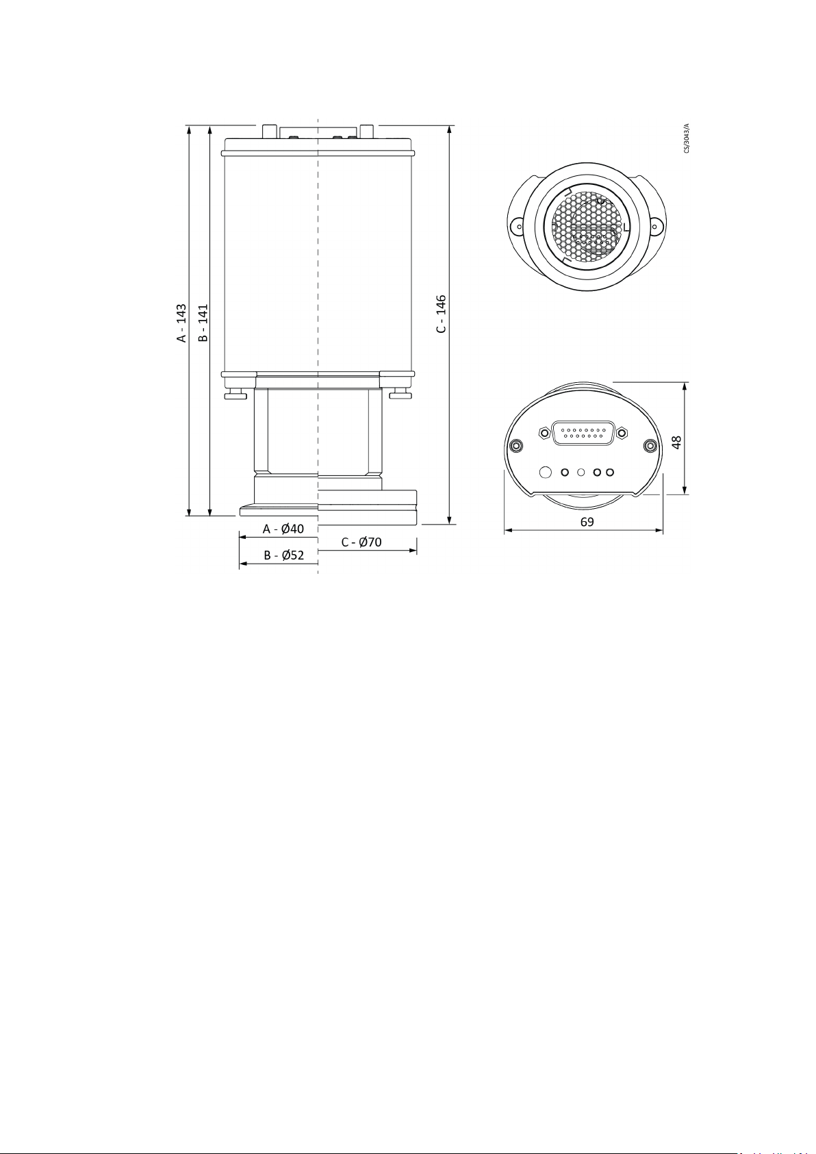
Figure 1 Dimensions
A. D14750100
B. D14750110
C. D14750120
Page 12
D14750880_A - Installation
Installation
Installation notes
For open buildings and operation rooms without air conditioning:
Vacuum connection
Remove the protective cover. Store the cover for future maintenance.
Make the vacuum connection with a small flange DN25 ISO KF, DN40 ISO KF or
conflat flange DN40CF.
Use clamps which can open and close with applicable tools only (for example, a strap
retainer tension ring), use sealing rings with a centring ring.
Make sure that the sensor flange is connected to ground, for example, by having
electrical contact to the grounded vacuum chamber (use metallic clamps).
The transducer can be installed in any orientation. If installed with the flange at the top, it can
lead to early contamination and malfunction.
An upright orientation with the flange to the bottom is recommended to keep particles and
condensates out of the sensor cell. The transducer is adjusted in the upright position.
Reorientation without a readjustment will decrease accuracy at pressures above 20 mbar.
Installation location: Indoor
Temperature: +5 °C to +60 °C
Relative humidity: Maximum 80% up to 30 °C, maximum 50% at 40 °C,
non-condensing
Air pressure: 860 to 1060 mbar
CAUTION: DAMAGE TO EQUIPMENT
Risk of damage to equipment. Dirt and damage can have a bad effect on the function of
the transducer.
WARNING: PRESSURIZED CONTAINER
Risk of injury or death. A release of parts and process gases because of system
overpressure more than 1 bar causes a hazard. Do not open any clamps while the vacuum
system is pressurized. Use clamps designed for overpressure conditions.
WARNING: PRESSURIZED CONTAINER
Risk of injury or death. A release of process gases because of system overpressure more
than 1.5 bar causes a hazard. KF flange connections with elastomer seals cannot resist
such pressures. Use O-rings with an outer centring ring.
Page 13
D14750880_A - Installation
Electrical connection
Operation with other supply and evaluation units
The transducer can operate with customer related display units or voltage supplies.
Use an applicable cable for the electrical connection and consider the EMI demands while you
refer to the pin description shown in Figure 2 on page 14.
WARNING: NOT FAIL-SAFE DESIGNED
Risk of death. Do not use the gauge for safety critical applications. The gauge is not
intended to be fail-safe.
CAUTION: DAMAGE TO EQUIPMENT
Risk of damage to equipment. Prevent forced twisting or violent opening when you install
the transducer. This can damage the transducer.
CAUTION: DAMAGE TO EQUIPMENT
Risk of damage to equipment. Do not connect or disconnect the transducer when the
cable is on circuit.

Page 14
D14750880_A - Installation
Figure 2 Pin description
Note:
We recommend to have a shield (Pin 12) and a supply common (Pin 5) grounded in the supply
unit.
CAUTION: DAMAGE TO EQUIPMENT
Risk of damage to equipment. An incorrect connection or supply voltage can damage the
transducer. Make sure the supply is connected and is of the correct voltage.
Socket Type Sub-D, 15-pole, male
Pin 1: Identification: 160 kΩ
Pin 2: Signal output 0-10 V d.c.
Pin 3: AGND
Pin 4: Voltage supply 24V d.c.
Pin 5: Supply common
Pin 6: Relay 1, N.O.
Pin 7: Relay 1, common
Pin 8: Relay 1, N.C.
Pin 9: Degas, external
Pin 10: RS485 +
Pin 11: RS485 -
Pin 12: Shield
Pin 13: Relay 2, N.O.
Pin 14: Relay 2, common
Pin 15: Relay 2, N.C.

Page 15
D14750880_A - Operation
Operation
General
Measurement principle
The transducer has a Pirani/hot cathode internal combination sensor.
The Pirani principle uses the heat conduction of gases to measure vacuum. A sensor filament
in a Wheatstone bridge circuit is heated to a constant temperature, so the bridge voltage is a
measure for total gas pressure.
The hot cathode sensor of Bayard Alpert type ionizes gas molecules by electron
bombardment. The ion current that results is a measure for the number of gas molecules in
the sensor and proportional to the absolute pressure.
Output signal
The output signal 1.219 to 8.6 V of your transducer has a logarithmic dependence on pressure
over the whole measurement range of 5.0 x 10⁻¹⁰ to 1000 mbar.
Conversion of the voltage signal and pressure is done according to the following formula:
Vout/V = 0.6 log (p/mbar) + 6.8
p/mbar = 10((Vout/V - 6.8)/0.6)
Serial interface RS485
The absolute pressure measured can be read out digitally by the transducers serial RS485
interface. Additionally you can set various parameters like gas correction factors or setpoints.
For further information see Communication on page 20.
Warm-up time
The signal output of the transducer is available for approximately 2 seconds after the unit is
switched on. To get the maximum accuracy of the unit, you should allow 5 minutes for
stabilization, especially when extreme pressure changes have occurred.
Accuracy
The unit is adjusted ex works in the upright position and a 24 V d.c. voltage supply. Through
contamination, ageing, extreme climatic conditions or alternate mounting orientation,
readjustment can become necessary. Accuracy is decreased in the range above
20 mbar.
Dependence on gas type
The composition and the type of the gas being measured controls the output signal. The unit
is adjusted for nitrogen and dry air. For other gases correction factors for both sensor types
can be set by the RS485 (see Sensor parameters on page 23). This results in a correct pressure
display below 0.1 mbar.
Page 16
D14750880_A - Operation
Operate the transducer
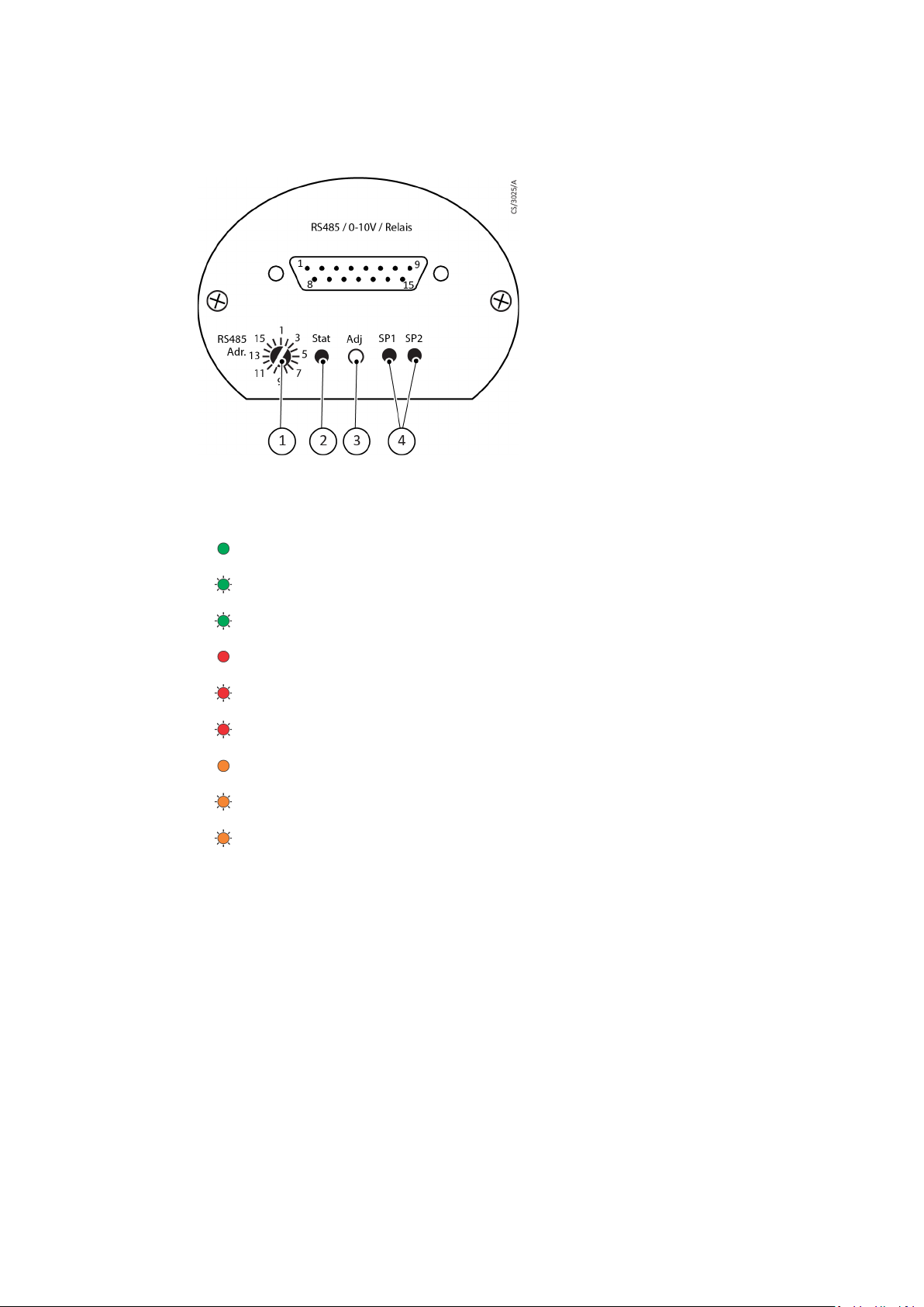
Figure 3 General arangement
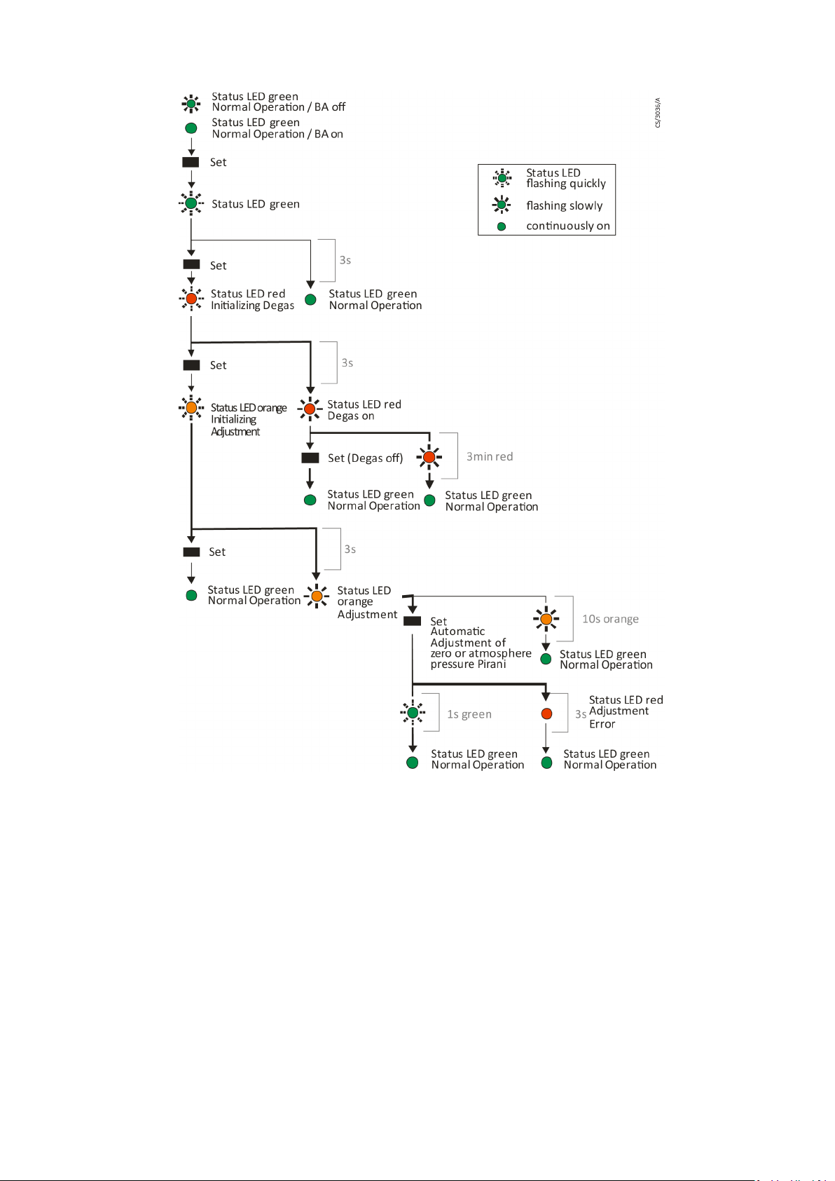
The transducer has a status LED which indicates the following operational states:
The switch-point LEDs are illuminated when the related relay is activated.
The transducer ADJ pushbutton can start the "degas" and "adjustment" functions.
Normal operation/hot cathode on (green LED continuously on)
Normal operation/hot cathode off (green LED flashes slowly)
Initialize input (green LED flashes quickly)
Error (red LED continuously on)
Degas on (red LED flashes slowly)
Initialize degas (red LED flashes quickly)
Warning: Hot cathode filament 1 defective (orange LED continuously on)
Ready for adjustment (orange LED flashes slowly)
Initialize adjustment (orange LED flashes quickly)
1. Address switch
2. Status LED
3. Pushbutton
4. Switch-point LEDs
Page 17
D14750880_A - Operation
Degas
Deposition or adsorbed gas molecules on the electrodes of the hot cathode sensor may lead
to increased degassing in ultra-high vacuum or even cause instabilities of the measurement
signal.
If this occurs, clean the sensor anode from the deposited material and adsorbed gas molecules
by degassing. This is done at pressure below 2.0 x 10⁻⁶ mbar by ohmic heating of the anode to
temperatures approximately 800 °C.
Degas control by pushbutton
The degas function can be activated by the pushbutton on the transducer (see Operate the
transducer on page 16).
Page 18
D14750880_A - Operation
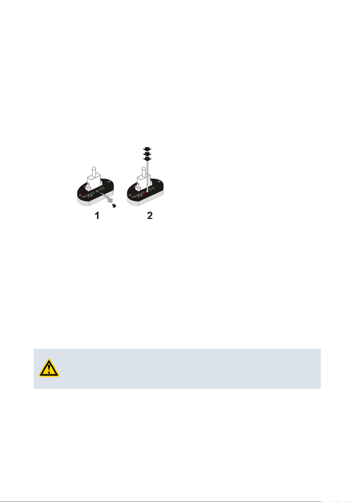
To do this:
1. Remove the rubber cap above the ADJ pushbutton (1).
2. Press the button several times with a small screwdriver or similar tool (2) until the
red status LED starts flashing quickly.
3. After 3 seconds, the degas process starts, red status LED flashes slowly.
4. The degas procedure will end automatically after approximately 3 minutes. To stop
the degas procedure anytime before the process ends automatically, press any key.
5. Insert the rubber cap again.
Figure 4 Manual degas
Degas control by external voltage signal
Degas is started when you connect Pin 9 (see Operation with other supply and evaluation units
on page 13) to GND for a minimum of 20 milliseconds.
The degas procedure will stop automatically after approximately 3 minutes, but can be
stopped any time by reconnecting Pin 9 to its previous state.
The red status LED flashes when the sensor degasses.
Degas control with a software command
See Sensor parameters on page 23.
Bake-out
When a bake-out operation of the vacuum chamber is done with the transducer being
installed to the chamber, the temperature at the sensor flange must be less than 180 °C.
CAUTION: DAMAGE TO EQUIPMENT
Risk of damage to equipment. The voltage supply to the transducer must be stopped
while the chamber is heated. If not, damage to the electronic components can result.
Table of contents
Other Edwards Industrial Equipment manuals

Edwards
Edwards GV250 User manual

Edwards
Edwards E1M40/80 Installation instructions

Edwards
Edwards HV8000 aftercooler Mk4 User manual

Edwards
Edwards Iron Worker User manual

Edwards
Edwards ELD500 Series User manual

Edwards
Edwards CDP User manual

Edwards
Edwards AIM-P-NW25 User manual

Edwards
Edwards FL20K User manual

Edwards
Edwards APG-M-NW16 AL User manual
Edwards
Edwards AdaptaBeacon 96DV2-N5 Series User manual


