manuals.online logo
Brands
  1. Home
  2. •
  3. Brands
  4. •
  5. Flash Furniture
  6. •
  7. Indoor Furnishing
  8. •
  9. Flash Furniture ZG-021-WH-GG User manual

Flash Furniture ZG-021-WH-GG User manual

Thank
you
for
your
purchase!
Customer Service Email: [email protected] | Phone: 866-552-2810
ZG-021-WH-GG / ZG-021-GY-GG
ASSEMBLY INSTRUCTIONS
Before You Begin:
Please identify all component parts and hardware pieces required before you begin. Carefully remove all of the
components from the packaging and set aside for assembly. Assemble on a soft surface to prevent scratching
during assembly.
Caution:
Tighten all components securely before use. Failure to do so may result in personal injury.
DO NOT use any sharp objects to open plastic wrapped components as damage to product or components may
result.
Warning:
CHOKING HAZARD - Small Parts. Adult Assembly Required.
DO NOT ALLOW CHILDREN TO CLIMB ON FURNITURE
Serious or fatal injuries can occur from furniture tipping over. You must install Tipping Restraint Hardware (where
included) to help prevent the unit from tipping and causing accidental injury, instability, death or damage. The
tipping restraint is intended only as a safety measure, it is not a substitute for proper adult supervision.
To help prevent furniture from tipping over it must be permanently attached to the wall. Anti-Tip Safety Wall
Straps suitable for the unit weight and wall materials (if not included) should be purchased and installed.
TV Stand
Have a Question/Concern?
Quality products and first-class customer service are the cornerstone of long-lasting
consumer relationships. We strive toward excellence in all we do and want you to be
completely satisfied with your purchase.
Please contact our exceptional Customer Experience Agents at the email address
or phone number shown below to assist you with any product questions or
issues before requesting a return.
We look forward to serving you in a friendly, efficient manner to resolve any issues you
may have.
Customer Service Email: CustomerExperience@belnick.com
Customer Service Phone: 866-552-2810
Our Warranty Statement
This warranty covers manufacturing defects associated with your new product. The product is
warranted from the original purchase date and to the original purchaser for normal usage,
according to the below-referenced specifications and limitations.
Non-moving metal parts are warranted for 5 years.
Component parts including pneumatic cylinder, control mechanism, base and casters are
warranted for 2 years.
All other items are warranted for 1 year.
Normal usage means use in compliance with the restrictions and weight limits specified for the
product. In the absence of product-specific restrictions and weight limits, normal usage means use
for no more than forty hours per week by persons weighing 250 lbs. or less. Coverage terminates if
the product is sold or otherwise transferred. Repairs made by parties other than Belnick also void
this warranty.
This warranty will not cover: (1) labor, freight, or damage from misuse, abuse, negligence,
alteration, assembly, installation, attachments, accident, vandalism, acts of nature or any other
event beyond the control of Belnick; (2) tearing, scratching, scuffing, or blemishing of leather or
fabric; (3) cosmetic damage that may result from normal usage; (4) damage attributable to use by
persons exceeding specified weight limits or commercial use exceeding forty hours per week; or (5)
rust or other damage caused by exposure to moisture. The user assumes all risk of injury resulting
from use of this product. Liability for incidental or consequential damage is excluded. Some states
do not allow the exclusion or limitation of incidental or consequential damages, so the above
limitation or exclusion may not apply to you.
Safety and Care Advice
Important – Please read these instructions fully before starting assembly
• Check you have all the
components and tools listed on
the following pages.
plastic bags and separate them
into their groups.
• Keep children and animals
away from the work area, small
parts could choke if swallowed.
• Make sure you have enough
space to layout the parts before
starting.
Care and maintenance
• Only clean using a damp cloth
and mild detergent, do no use
bleach or abrasive cleaners.
• From time to time check that
there are no loose screws on
this unit.
• This product should not be
discarded with household waste.
Take to your local authority
waste disposal centre.
Handy Hints
• Assemble all parts and bolts
loosely during assembly, only
once the product is complete
should you fully tighten the bolts
• Regularly check and ensure
tightend properly.
• During assembly do not stand
or put weight on the product,
this could cause damage.
• Assemble the item as close
room) as possible.
• Assemble on a soft level
surface to avoid damaging the
• Parts of the assembly will be
easier with 2 people.
• To reduce
the likelihood of
damaging your
product please
ensure that your
power drill is set on a low torque
setting.
WARNING
In order to help prevent overturning –
To help prevent product toppling over please follow the below steps:-
Do not open more than one drawer at a time
Do not place heavy items in the top drawers
Do not place heavy items on top of the furniture, unless the furniture has been
designed for this purpose
You will need to provide wall plugs and screws applicable for your wall type
!
• Remove all fittings from the
to its final position (in the same
unit or your floor.
That all bolts and fittings are
please follow these instructions
Do not allow children to climb or hang on the furniture
Use the anti tip stap or wall fixing method provided (if applicable)
please note that only the anti tip strap is provided.
Components -Panels
Please check you have all the panels listed below
1
.
) Le Front Leg X 1 2
.
) Le Rear Leg X 1 3
.
) Right Front Leg X 1 4
.
) Right Rear Leg X 1
5
.
) Le Side Panel X 1 6
.
) Right Side Panel X 1 7
.
) Bottom
Panel
X 1 8
.
) Bottom Trim X 1
9
.
) Middle Foot X 2 10
.
) Le
C
enter Panel X 1 11
.
) Right
C
enter Panel X 1 12
.
) Slide Rail X 1
0
0
13
.
) Side Back Panel X 2 14
.
) Middle Back Panel X 2 15
.
) Top Panel X 1
17
.
)
C
enter Shel
f
X 1 18
.
) Le
D
oor X 1 18
.
) Right
D
oor X 1
16
.
) Le
f
t
&
Right Shel
v
es X 2
Components -Fittings
Please check you have all the panels listed below
Note:  

    e '
 
  
 
  
 
   \=]
 
  -
-

A

-
 


 
A



•

 ttttt\Jl@

Tools required
 
 
D I 
3
Using Camlocks
12
DO NOT OVER TIGHTEN.
NE PAS SERRER EXCESSIVEMENT.
34
4
Step 1
Step 3
Step 2
Step 4
Connect the male
camlock as diected in
the assembly instructions
using a scewdriver.
Push the male camlock
into the entry hole.
Insert the femle
camlock as shown in the
instruction.
Note:ensure that the
arrow on the top of the
camlock points towards
the entry hole for the
male camlock.
Turn the female camlock
clockwise with a
screwdriver.
You should feel a click
when the camlock is
locked in place.
The joint is now secure.
Assembly Instructions
Top Panel
Rear Left Leg
Left Side
Panel
Front Left Leg
Left Door
Middle Support Legs
Right Door
Bottom Trim
Bottom Panel
Left Shelf
Right Shelf
Center Shelf
Front Right Leg
Rear Right Leg
Right
Side
Panel
Rear Center
Panel
Left Rear
Panel
Right Rear
Panel
Left
Center
Panel
Right
Center
Panel
Slide Rail
Assembly Instructions
Step 1
Step 2
AAA
AA
A
AA
A
AA
A
A
A
A
A
C
C
C
C
C
C
C
C
Insert (12) Male Camlocks (Part A) into the Front and Rear Legs (Parts 1, 2, 3, & 4) as
shown. Tighten with a Phillips Screwdriver.
Front Left Leg Rear Left Leg Front Right Leg
Rear Right Leg
Male Camlock
Phillips
Screwdriver
NOTE: Ensure
grooves on back
legs face inward
and towards
each other.
Insert (4) Male Camlocks (Part A) and (8) Wood Dowels into the Left Side Panel (Part 5)
and Right Side Panel (Part 6) as shown. Tighten Camlocks with a Phillips Screwdriver.
Left Side Panel
Right Side Panel
Wood Dowel
Male Camlock
Assembly Instructions
Step 3
Step 4
1 2 3
C
C
CC
C
BB
BB
B
B
B
B
Insert (8) Female Camlocks into the Left and Right Side Panels as shown
then insert the Male Camlocks on the Legs into the Female Camlocks then
turn clockwise to tighten using a Phillips Screwdriver.
NOTE: Ensure arrows on Female Camlocks face outward toward the receiver holes.
Female
Camlocks
Insert (5) Wood Dowels (Part C) into the Bottom Panel
(Part 7) and Bottom Panel (Part 8) as shown.
Bottom Panel
Wood Dowel
Bottom Trim
Right Front Leg
Right Rear Leg
Left Rear Leg
Left Front Leg
Left Side
Panel
Right Side
Panel
Assembly Instructions
Step 5
Step 6
E
E
F
O
O
Attach (2) Middle Support Legs (Part 9) to the underside of the Bottom
Panel (Part 7) using (2) 6*50mm Screws (Part E). Tighten using Allen
Wrench (Part F).
Allen Wrench
6*50mm Screw
Bottom Panel
Middle Support Legs
Attach Bottom Trim (Part 8) to the underside of the
Bottom Panel (Part 7) using (2) 4*45mm Screws.
Tighten using a Phillips Screwdriver.
NOTE: Ensure Wood Dowels are properly
seated before tightening screws.
Bottom Trim
4*45mm
Screw
Bottom Panel
Assembly Instructions
Step 7
Step 8
E
E
E
E
C
C
C
C
F
Insert (4) Wood Dowels (Part C) into the Left Center Panel (Part 10) and
the Right Center Panel (Part 11).
Left Center Panel
Right Center Panel
Insert Left and Right Center Panels into the top side of the Bottom Panel
(Part 7) and secure using (4) 6*50mm Screws (Part E). Tighten using Allen
Wrench (Part F).
NOTE: Ensure notches are
facing the front of the cabinet.
Right
Center
Panel
Left
Center
Panel
6*50mm
Screw
Allen Wrench
NOTE: Ensure Wood Dowels are properly seated before tightening screws.
NOTE: Ensure grooves in Center Panels align
with grooves in rear of bottom panel.
Assembly Instructions
Step 9
Step 10
1 2 3
C
C
B
BB
B
Insert (2) Wood Dowels (Part C) into the Slide Rail (Part 12).
Wood Dowel
Slide Rail
Insert (4) Female Camlocks into the right side of the Slide Rail, Bottom Panel, and Bottom
Trim as shown. Insert Male Camlocks into the Female Camlocks and tighten using a Phillips
Screwdriver.
Slide Rail
Female
Camlock
Right Side
Panel
Right Front
Leg
Right Rear
Leg
NOTE: Ensure grooves in
Right Side Panel aligns with
grooves in bottom panel.
NOTE: Ensure arrows on Female Camlocks face outward toward the receiver holes.
Assembly Instructions
Step 11
Step 12
1 2 3
B
B
B
B
N
Insert (4) Female Camlocks into the left side of the Slide Rail, Bottom
Panel, and Bottom Trim as shown. Insert Male Camlocks into the Female
Camlocks and tighten using a Phillips Screwdriver.
Side Rail
Female
Camlock
Left Side
Panel
Left Center
Panel
Right Center Panel
Right Side
Panel
Bottom Panel
NOTE: Ensure
grooves in Left Side
Panel aligns with
grooves in bottom
panel.
Insert Left & Right Rear
Side Panels (Part 13) into
the grooves in the Side and
Center Panels as shown.
Insert (1) Rear Center Panel (Part 14) into
the grooves in the Center Panels. Insert (1)
H-Bar (Part N) then insert the last Rear
Center Panel (Part 14).
NOTE: Ensure all panels
are properly seated in the
grooves and H-Bar.
Rear Center Panel
Left Rear
Panel
Right
Rear
Panel
Rear Center Panel
H-Bar
Left
Side
Panel
Right
Side
Panel
Left Center
Panel
Right Center
Panel
NOTE: Ensure arrows on Female Camlocks face outward toward the receiver holes.
Assembly Instructions
Step 13
Step 14
CCCC
CC
CC
CCCC
A
A
A
A
A
A
A
A
A
A
Insert (12) Wood Dowels (Part C) into the
assembled cabinet as shown.
Insert (10) Male Camlocks (Part A) into the underside of the Top Panel
(Part 15) as shown. Tighten using a Phillps Screwdriver.
Top Panel
Male Camlock
Assembly Instructions
Step 15
Step 16
1 2 3
BB
B
B
BB
D
DD
DD
D
D
D
D
D
D
D
D
Insert (10) Female
Camlocks (Part B) into
the cabinet as shown.
Place the Male Camlocks in
the Top Panel (Part 15) into
the Female Camlocks in the
Cabinet. Tighten using a
Phillips Screwdriver.
Top Panel
Female Camlock
NOTE: Ensure arrows on Female Camlocks face outward toward the receiver holes.
Insert (12) Shelf Support Pins into the holes in the Side and Center
Panels.
Shelf Support Pins
Assembly Instructions
Step 17
Step 18
H
H
H
H
K
K
K
K
J
J
J
J
I
I
I
I
D
D
Insert the Center Shelf (Part 17) and the Left and Right Side Shelves (Part
16) into the assembled cabinet to rest on the Shelf Support Pins (Part D).
Left Side Shelf
Right Side Shelf
Center Shelf
Attach (4) Plates (Part K) onto the inside bottoms of the Left Door (Part 18)
and Right Door (Part 19) using (8) 4*12mm Screws (Part H). Tighten using
a Phillips Screwdriver.
Attach (4) Pulleys (Part I) to the inside tops of
the Left & Right Doors using (8) 6*12mm
Screws (Part J). Tighten using a Phillips
Screwdriver.
Left Door
Right Door
Plate
4*12mm Screw
Pulley
6*12mm
Screw
Assembly Instructions
Step 19
Step 20
G
G
1
2
Attach Handles (Part G) to the Left & Right Doors using included
screws. Tighten using a Phillips Screwdriver.
Right Door
Left Door
Handle
Insert the Plates into the grooves in the Bottom Trim.
Lift up on the door to seat the Pulley onto the Slide Rail.
Assembly Instructions
Step 21
Step 22
L
L
L
unit is secured to the
The unit is floor
standing, but it is
recommended that the
wall.
1. Move the unit into
desired position.
2. Mark the wall with a
suitable scribe the
position of the fixing
holes.
Warning:
Before driling,check
wall for hidden pipes
and cables.
!
3. Drill holes and insert 2 x
wall plug
4. Attach 2 x Wall Straps to
to the top of the unit using 2 x
Washers and 2 x Screws
5. Secure the straps to the
wall using 2 x Washers
and 2 x Screws
Note: To hide the straps
behind the unit, drill the
holes lower than the top of
M
M
Attach (14) Plastic Wedges (Part L) into the back panels as shown.
Attach using included screws and tighten using a Phillips Screwdriver.
1. Attach (2) Wall Straps to the unit using
the included Washers and Screws.
2. Move unit into the desired position and
mark the wall with a pencil where the
top of the Wall Strap will be attached.
3. Drill a hole in the wall and insert Wall
Anchors.
4. Move unit back into the desired position and
insert Screws in Wall Anchors and tighten using a
Phillips Screwdriver or Power Drill.
Wall Strap
Plastic Wedge

This manual suits for next models

1

Other Flash Furniture Indoor Furnishing manuals
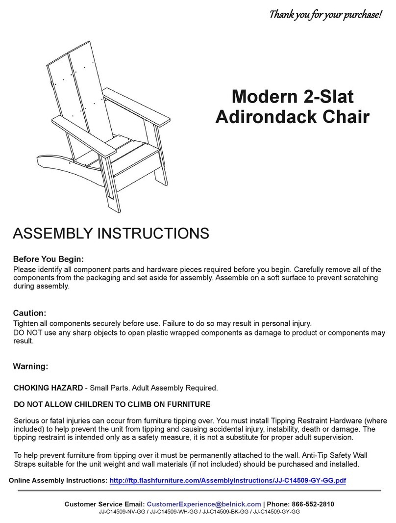
Flash Furniture GO-2286M-GG User manual
Flash Furniture

Flash Furniture GO-2286M-GG User manual

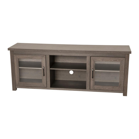
Flash Furniture Modern JJ-C14509-NV-GG User manual
Flash Furniture

Flash Furniture Modern JJ-C14509-NV-GG User manual

Flash Furniture GC-MBLK65-BK-GG User manual

Flash Furniture

Flash Furniture GC-MBLK65-BK-GG User manual

Flash Furniture YK-1077-BEIGE-K-GG User manual

Flash Furniture

Flash Furniture YK-1077-BEIGE-K-GG User manual

Flash Furniture Mid-Century Modern Loveseat Sofa User manual
Flash Furniture

Flash Furniture Mid-Century Modern Loveseat Sofa User manual

Flash Furniture Fundamentals LF-134-WH-GG User manual

Flash Furniture

Flash Furniture Fundamentals LF-134-WH-GG User manual

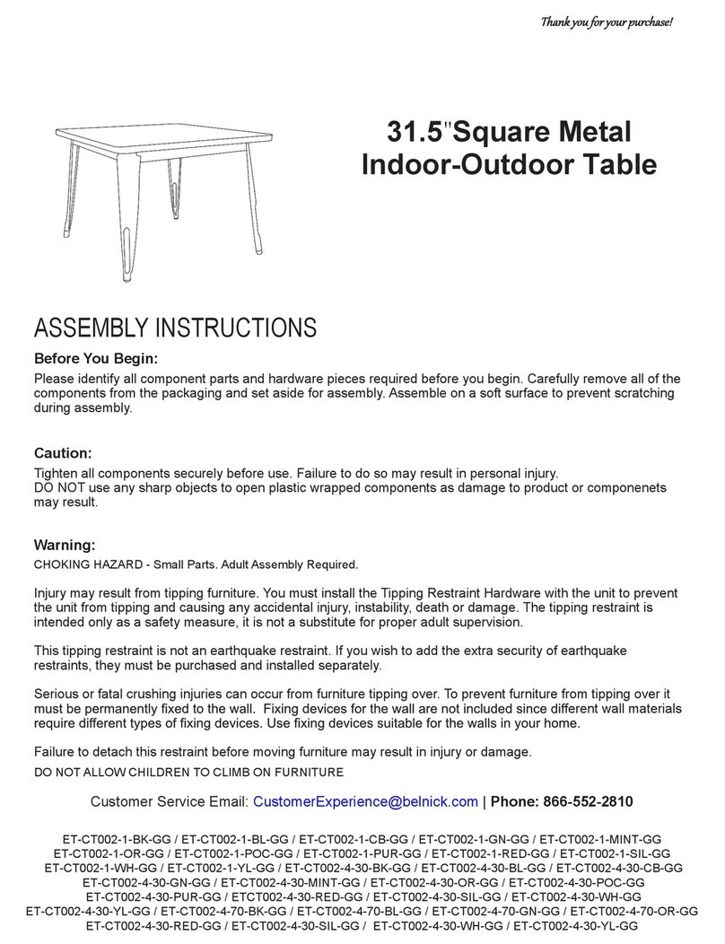
Flash Furniture ZG-034-WOAK-MARB-GG User manual
Flash Furniture

Flash Furniture ZG-034-WOAK-MARB-GG User manual

Flash Furniture ET-CT002-1-BK-GG User manual
Flash Furniture

Flash Furniture ET-CT002-1-BK-GG User manual

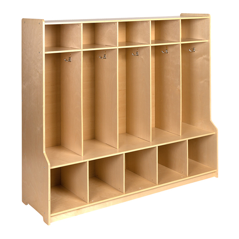
Flash Furniture MK-LCKR001-GG User manual
Flash Furniture

Flash Furniture MK-LCKR001-GG User manual

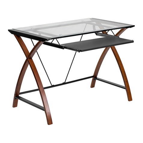
Flash Furniture ZG-036-GY-GG User manual
Flash Furniture

Flash Furniture ZG-036-GY-GG User manual

Flash Furniture NAN-JN-2824S-GG User manual

Flash Furniture

Flash Furniture NAN-JN-2824S-GG User manual
Flash Furniture NAN-JN-2824S-GG User manual

Flash Furniture

Flash Furniture NAN-JN-2824S-GG User manual

Flash Furniture H-966F-2-GG User manual

Flash Furniture

Flash Furniture H-966F-2-GG User manual

Flash Furniture CH-00288-WH-GG User manual
Flash Furniture

Flash Furniture CH-00288-WH-GG User manual

Flash Furniture TW-WTCS-1001-GRY-GG User manual
Flash Furniture

Flash Furniture TW-WTCS-1001-GRY-GG User manual

Flash Furniture ZG-038-GY-GG User manual
Flash Furniture

Flash Furniture ZG-038-GY-GG User manual

Flash Furniture GO-2286H-GG User manual
Flash Furniture

Flash Furniture GO-2286H-GG User manual

Flash Furniture GC-MBLK61-BK-GG User manual
Flash Furniture

Flash Furniture GC-MBLK61-BK-GG User manual

Flash Furniture NAN-CLIFTON-RU-GG User manual
Flash Furniture

Flash Furniture NAN-CLIFTON-RU-GG User manual

Flash Furniture YKC-1090-K-WAL-GG User manual

Flash Furniture

Flash Furniture YKC-1090-K-WAL-GG User manual

Flash Furniture ZG-035-GY-GG User manual

Flash Furniture

Flash Furniture ZG-035-GY-GG User manual

Flash Furniture ZB-WING-BK-LEA-GG User manual

Flash Furniture

Flash Furniture ZB-WING-BK-LEA-GG User manual

Flash Furniture NAN-JN-2824SL-COMBO-GG User manual

Flash Furniture

Flash Furniture NAN-JN-2824SL-COMBO-GG User manual

Flash Furniture BT-70597-1-GG User manual

Flash Furniture

Flash Furniture BT-70597-1-GG User manual

Popular Indoor Furnishing manuals by other brands

Regency LWMS3015 Assembly instructions

Regency

Regency LWMS3015 Assembly instructions

Furniture of America CM7751C Assembly instructions

Furniture of America

Furniture of America CM7751C Assembly instructions

Safavieh Furniture Estella CNS5731 manual

Safavieh Furniture

Safavieh Furniture Estella CNS5731 manual

PLACES OF STYLE Ovalfuss Assembly instruction

PLACES OF STYLE

PLACES OF STYLE Ovalfuss Assembly instruction

Trasman 1138 Bo1 Assembly manual

Trasman

Trasman 1138 Bo1 Assembly manual

Costway JV10856 manual

Costway

Costway JV10856 manual

moss DESIGN Caisson Credenza Assembly instructions

moss DESIGN

moss DESIGN Caisson Credenza Assembly instructions

Aquaglide FULL DECK 15.0 owner's manual

Aquaglide

Aquaglide FULL DECK 15.0 owner's manual

AREBOS AR-HE-SW30 user manual

AREBOS

AREBOS AR-HE-SW30 user manual

Till-Hilft Fulda 87005.330 Assembly instructions

Till-Hilft

Till-Hilft Fulda 87005.330 Assembly instructions

Twoey Outside 2010 quick start guide

Twoey Outside

Twoey Outside 2010 quick start guide

Hettich Easys 200 operating instructions

Hettich

Hettich Easys 200 operating instructions

The bedboss RELAX 404 Series owner's manual

The bedboss

The bedboss RELAX 404 Series owner's manual

Oeseder Möbelindustrie Bern 991 720 Assembly instructions

Oeseder Möbelindustrie

Oeseder Möbelindustrie Bern 991 720 Assembly instructions

Costway HW68469 user manual

Costway

Costway HW68469 user manual

Next ALIX A27743 Assembly instructions

Next

Next ALIX A27743 Assembly instructions

BROSA Hans Assembly guide

BROSA

BROSA Hans Assembly guide

Prodigg MINIKA PBA015T-FUR installation manual

Prodigg

Prodigg MINIKA PBA015T-FUR installation manual

manuals.online logo
manuals.online logoBrands
  • About & Mission
  • Contact us
  • Privacy Policy
  • Terms and Conditions

Copyright 2025 Manuals.Online. All Rights Reserved.