Flexitron TAXITRONIC TX80 Urba User manual

INSTALLATION MANUAL TX80 URBA ONE INTERFACOM, S.A.U. 02/03/2022
Inst TX80_urba_one_003_EN.doc 13/10/2021
INSTALLATION MANUAL
TX80 URBA ONE

INSTALLATION MANUAL TX80 URBA ONE INTERFACOM, S.A.U.
Inst TX80_urba_one_003_EN.doc 2
TABLE OF CONTENTS
1. INTRODUCTION.................................................................................................................... 3
2. INSTALLATION......................................................................................................................3
2.1. TX80 URBA ONE LOCATION AND INSTALLATION ....................................................... 3
3. ELECTRICAL INSTALLATION .............................................................................................. 4
4. SEALING................................................................................................................................ 8
5. TECHNICAL CHARACTERISTICS........................................................................................ 9
6. IMPULSE GENERATOR......................................................................................................10
6.1. INTRODUCTION.............................................................................................................10
6.2. INSTALLATION...............................................................................................................10
6.2.1. ASSEMBLY OF THE SPEEDOMETER CABLE AND PULSE GENERATOR............10
6.2.2. CABLE CONNECTION, COVER CLOSING AND PULSE GENERATOR SUPPORT12
6.3. SEALING.........................................................................................................................13
6.4. TECHNICAL CHARACTERISTICS.................................................................................13
7. VEHICLES WITH ELECTRONIC IMPULSE SIGNAL.......................................................... 13
8. ERROR MESSAGES...........................................................................................................14

INSTALLATION MANUAL TX80 URBA ONE INTERFACOM, S.A.U.
Inst TX80_urba_one_003_EN.doc 3
1. INTRODUCTION
The focus of this document is the description of the TAXITRONIC TX80 URBA ONE right
installation. the order in which the equipment installation and programming must be
carried out is established.
2. INSTALLATION
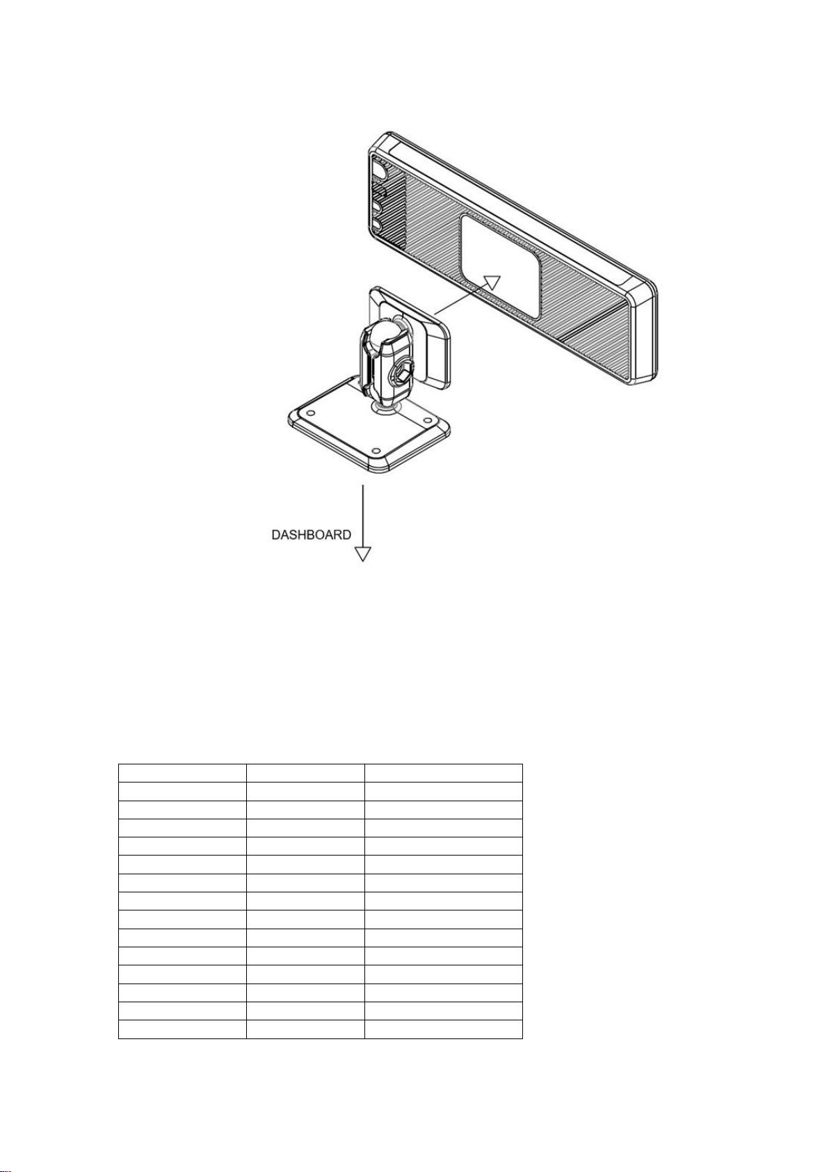
2.1. TX80 URBA ONE LOCATION AND INSTALLATION
The equipment is supplied with the connector window opened. It is not necessary to open
it to proceed with the connection. All the connectors of the TX80 URBA ONE are inside
the equipment. The connector window is located at the rear of the equipment, which will
be covered and sealed at the end of the installation.
The rest of the devices in the installation are interconnected with the TX80 URBA ONE, so
that the installation of the TX80 URBA ONE cannot be sealed until the rest of the
installation process is finished.
TX80 URBA ONE is fixed to the dashboard with an adhesive bracket. If the surface is
rough, so adhesive is not possible, the bracket base can also be fixed to the dashboard
with screws
1. Remove the adhesive backing from the bracket and attach it to the smooth back of the
TX80 URBA ONE evenly.
2. The adhesive resistance increases as it dries.
3. Adhere the bracket and the taximeter to the dashboard and adjust the height and
orientation.
After 20 min
50%
After 24 hours
90%
After 3 days
100%
INSTALLATION MANUAL TX80 URBA ONE INTERFACOM, S.A.U.
Inst TX80_urba_one_003_EN.doc 4
4. Once located and oriented, the lateral screw of the bracket must be tightened until the
equipment is fixed.
3. ELECTRICAL INSTALLATION
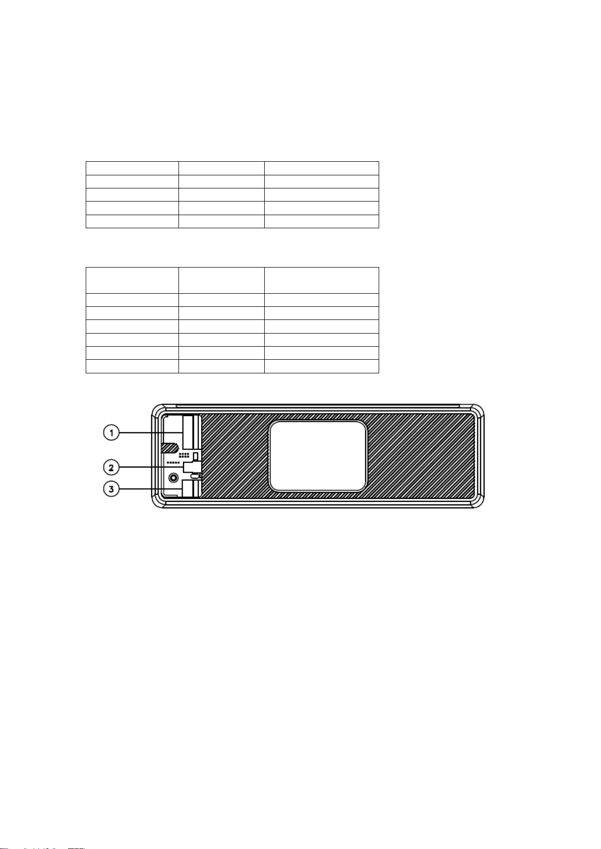
The TX80 URBA ONE Has the following connectors:
•(1) Power supply
Contact number
Colour
Function
1
-
-
2
Green/White
Distance pulses
3
-
L4
4
-
L3
5
-
L2
6*
Brown
Emergency signal
7
Violet
Passenger sensor
8
Blue
Contact key
9
Yellow
Position lights
10
Green
Rooflight (L1)
11
Red
+ 12V
12
Red
+ 12V
13
Black
Ground
14
Black
Ground
INSTALLATION MANUAL TX80 URBA ONE INTERFACOM, S.A.U.
Inst TX80_urba_one_003_EN.doc 5
•(2) Serial Rooflight
The connector on the cable has a white mark, which must be visible from the connectors
cover.
Contact number
Function
1
GND
2
+ 12V
3
TXD
TTL 0 –5 V
4
RXD
TTL 0-5 V
•(3) Serial Port (IR80)
Contact number
Function
1
+ 12 V
2
+ 5 V
4
TXD
TTTL Levels 0 - 5 V
5
RXD
6
GND

INSTALLATION MANUAL TX80 URBA ONE INTERFACOM, S.A.U.
Inst TX80_urba_one_003_EN.doc 6
•COMPLETE INSTALLATION

INSTALLATION MANUAL TX80 URBA ONE INTERFACOM, S.A.U.
Inst TX80_urba_one_003_EN.doc 7
RECOMMENDATIONS FOR THE ELECTRICAL INSTALLATION
- Disconnect the positive terminal on the battery until the whole electrical installation is
completed.
- Any manipulation of the taximeter or of the external lights must be done while the
taximeter is disconnected from the power supply
- Always take the positive and negative directly from the battery in order to avoid false
contacts and to obtain a more filtered power supply.
- Always connect the cables to the battery by means of a terminal, never by winding
the wires onto the contact.
- If the cables cross a plate to reach the taximeter, they should go through a protective
rubber casing.
- If the cables are too long, they should be cut to the required length and not rolled up
under any circumstances.
- If the vehicle has a radio transmitter, separate its installation from that of the taximeter
as far as this is possible.
- If it is possible no element that is connected to the taximeter should be fixed to the
same support as the aerial of the radio.
- Close the connectors cover before setting the taximeter to the bracket
- To set up the device and the charge of the tariff, the tariff screw has to be loosened. It
is enough and advisable not to take out totally the screw

INSTALLATION MANUAL TX80 URBA ONE INTERFACOM, S.A.U.
Inst TX80_urba_one_003_EN.doc 8
4. SEALING
- Seal Nº 1: Seals the taximeter box, preventing access to the electronic board.
- Seal Nº 2: Seals the connectors cover, so it seals the electrical installation and the tariff
connector.
To load the tariff and modify its parameters, the tariff cover must be loosened. In this way,
the pushbuttons located in the hole of the seal will not be pressed.
To finish the sealing, the tab of the tariff cover must be inserted inside the equipment
(below the rib marked in the image) in this way the connector is hidden and the
pushbuttons pressed.
The taximeter is prepared to be sealed with the plastic seal that has been supplied to
you. In some localities, a cable seal is necessary: If this type of seal is required, a square
and a screw with a drilled head are included in the equipment kit.

INSTALLATION MANUAL TX80 URBA ONE INTERFACOM, S.A.U.
Inst TX80_urba_one_003_EN.doc 9
5. TECHNICAL CHARACTERISTICS
The general technical characteristics of TX80 URBA ONE are as follows:
-Supply voltage:
-Nominal = 12 V
-Max = 30 V
-Min = 8 V
−Maximum consumption without external lights = 300 mA
−Maximum consumption taximeter off = 6 mA
−Maximum consumption inside battery = 5 A
−Maximum power 36 W for each external light of 60 W in case that 3 outputs are
connected in parallel.
-Impulse generator power supply = 5 V
-Impulse generator input signal:
-Level 0 = -1 to 2,5 V
-Level 1 = From 4 to 25 V
−Maintenance of the information disconnected from the vehicle’s battery = 5 years
−40 V surges of 10 ms.
−Resistance to electrostatic shocks of 6 kv (Contact), 8 kV (Air).
-Protection against inverse connection.
-Internal connector protective fuse of 1,85 A.
-External fuse of 4 A.
-Operating Temperature: -25 a +70 °C
-Storage temperature for keeping the information - 40 to + 85º C
Wide
High
Deep
TX80 URBA ONE
155
49
16
-"K” constant of the device from 500 until 80000 pulses per Km/ml.
-Mechanical environment M3
-Climatic environment E3
INSTALLATION MANUAL TX80 URBA ONE INTERFACOM, S.A.U.
Inst TX80_urba_one_003_EN.doc 10
6. IMPULSE GENERATOR
6.1. INTRODUCTION
−For the vehicles with mechanical speedometer, you have to use a pulse generator
that is managed by the taximeter.
−The pulse generator is inserted in the cable of the speedometer and converts the
mechanical movement of this cable in an electrical signal, which is amplified and
filtered by the taximeter.
6.2. INSTALLATION
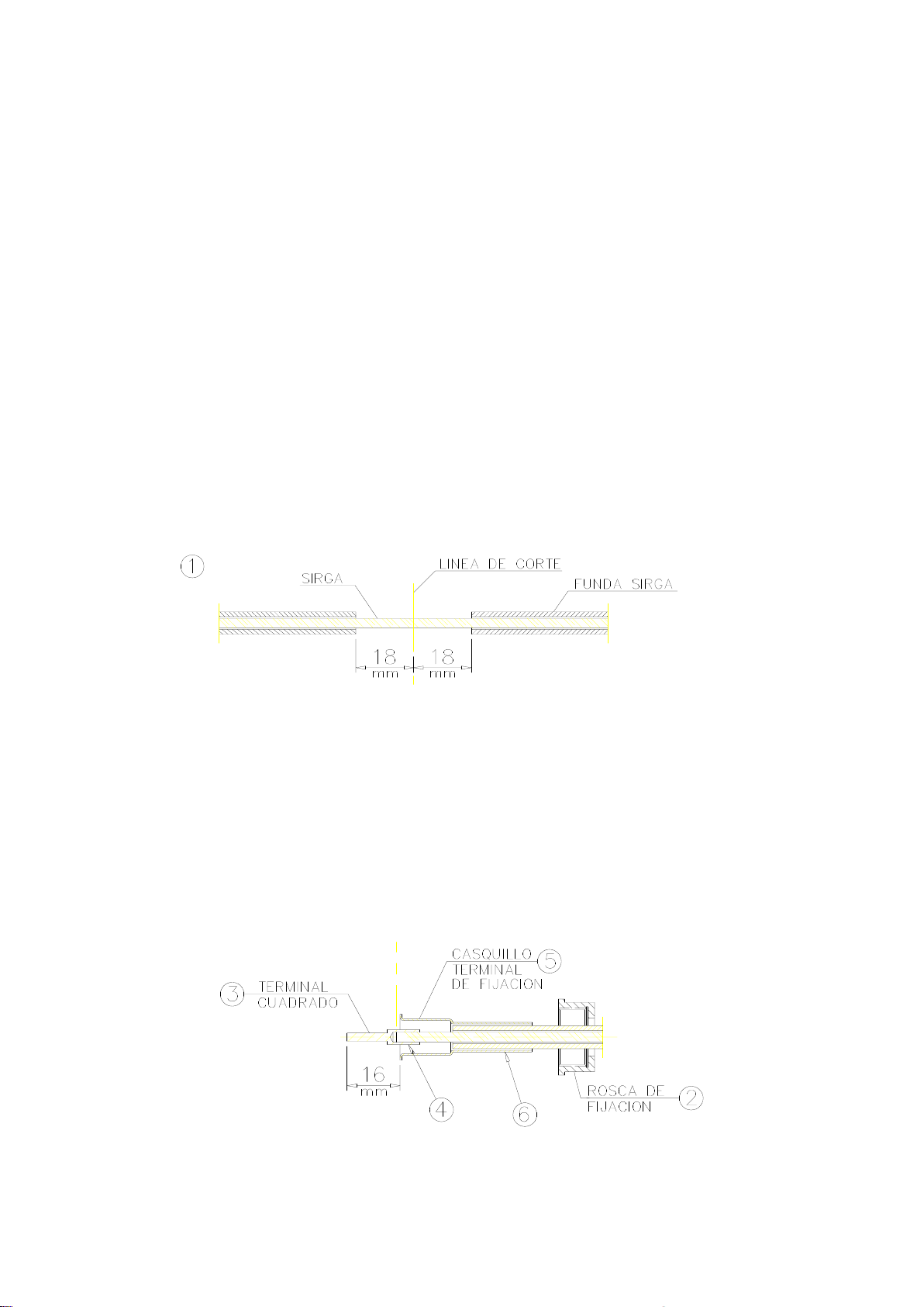
6.2.1. ASSEMBLY OF THE SPEEDOMETER CABLE AND PULSE GENERATOR
−First of all, part of the protecting cover of this cable must be removed and the cable
must be cut (item 1)
−A fixing ring (item 2) must be put in each of the two edges of the cable. The square
terminals (item3) are placed on the cable and are fixed by pressing on the zone
indicated with (4). This is done in position “A” or “B” of the pliers depending on the
diameter of the square terminal.
−Afterwards put the cover ends (item 5) and press them on the part indicated in item
6 in the position “C” of the pliers.

INSTALLATION MANUAL TX80 URBA ONE INTERFACOM, S.A.U.
Inst TX80_urba_one_003_EN.doc 11
−Finally, all pieces are assembled by screwing together the two fixing rings taking into
account that the separating space indicated by (8) must be sufficient.

INSTALLATION MANUAL TX80 URBA ONE INTERFACOM, S.A.U.
Inst TX80_urba_one_003_EN.doc 12
6.2.2. CABLE CONNECTION, COVER CLOSING AND PULSE GENERATOR
SUPPORT
−To connect the pulse generator cable, it is necessary to open the pulse generator
cover (item 1) after taking the closing screw out and moving the cover in the right
direction indicated by the arrow. Connect the cable as indicated on item 2 taking into
account the polarity of the connector.
−Finally put the pulse generator cover back, fix it or seal it, if it is necessary (item 3)
and place the pulse generator in the corresponding holder.

INSTALLATION MANUAL TX80 URBA ONE INTERFACOM, S.A.U.
Inst TX80_urba_one_003_EN.doc 13
6.3. SEALING
−The pulse generator installation can also be sealed, as shown in the image.
6.4. TECHNICAL CHARACTERISTICS
−The main technical characteristics of the pulse generator are:
−Sensor type: Hall effect cell
−Number of pulses / revolution: 4 with double impulses train
−Feeding voltage: 4 to 18 V
−Consumption at 5 V: 10 mA
7. VEHICLES WITH ELECTRONIC IMPULSE SIGNAL
-The distance signal supplied by the car can be connected in two possible ways:
-By connecting this signal to the Red/White wire on the Power Supply cable.
-By using the dedicated impulse generator connector, with a shielded cable, or even
mechanical shield, according to local regulations.
- The adaptation of the signals of the different vehicles is done by an internal electronic
circuit with the following characteristics:
•Hysteresis of the input is configurable
•It adapts to different levels
•Optional Pull–up
•Optional Pull–down
•Constant K is adjustable between 500 and 80000 km-1.
- All these adjustments are done from the tariff changer. It is necessary to unseal the
device.

INSTALLATION MANUAL TX80 URBA ONE INTERFACOM, S.A.U.
Inst TX80_urba_one_003_EN.doc 14
8. ERROR MESSAGES
−The possible error messages that may appear on the display are listed below.
-E-2 Roof lights failure: The roof lights are not correctly connected or some of its
bulb lights doesn’t work. This error is shown if it is enabled in the tariff.
-E-5 The taximeter is out of the configured revision period: This message is shown
when the taximeter is out of the configured revision period. It is resolved by setting
a new stop date or disabling it.
-E-6 Excess speeding. This error is shown if it is enabled in the tariff.
-E-7 Working time max exceeded: This error is shown when the hours of the shift
have finished. The error automatically disappears when you restart the day.
-E-8 Error in the tariff parameters: The taximeter has not the tariff loaded, or the
tariff loaded is wrong. The error is solved by charging tariff.
-E-10 Printer failure: The printer is not working, is incorrectly connected or has no
paper. This error is shown if it is enabled in the tariff.
-E-11 Serial number error: This error is displayed if the serial numbers are not
linked. The error is solved by charging tariff.
-E-12 RAM memory loss: This error is displayed if the device has a depleted battery
or there is a malfunction. The error is solved by replacing the internal battery of the
equipment.
-E-Z Anti Zapper error: A distance pulse error detected. This error is shown if it is
enabled in the tariff. The error is solved by charging tariff.
-E-NS Serial Number Pairing Error: This error is displayed when a TX80 is
connected to a device to which it is not paired. This pairing is done when charging
tariff.
Other manuals for TAXITRONIC TX80 Urba
2
Table of contents
Other Flexitron Measuring Instrument manuals

Flexitron
Flexitron MTX-StarSensor User manual

Flexitron
Flexitron webdyn MTX-StarWater User manual

Flexitron
Flexitron webdyn MTX-StarWater User manual

Flexitron
Flexitron TAXITRONIC TX80 Urba User manual

Flexitron
Flexitron webdyn MTX-StarEnergy-E User manual

Flexitron
Flexitron TAXITRONIC TX80 Urba User manual


