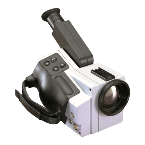
FLIR HM-224b Pro User manual

HM-Series
Thermal Night Vision Camera
Operator’s Manual
Document Number: 432-0004-31-10
Revision: 100
Jan 2013
HM_Series_Operators.book Page i Friday, January 18, 2013 4:27 PM

HM-Series Operator’s Manual
ii Jan 2013
© 2012 FLIR Commercial Systems, Inc. All rights reserved worldwide. No parts of this
manual, in whole or in part, may be copied, photocopied, translated, or transmitted to
any electronic medium or machine readable form without the prior written permission
of FLIR Commercial Systems, Inc.
Names and marks appearing on the products herein are either registered trademarks
or trademarks of FLIR Commercial Systems, Inc. and/or its subsidiaries. All other
trademarks, trade names, or company names referenced herein are used for
identification only and are the property of their respective owners.
This product is protected by patents, design patents, patents pending, or design patents
pending.
If you have questions that are not covered in this manual, or need service, contact FLIR
Commercial Systems, Inc. customer support at 805.964.9797 for additional
information prior to returning a camera.
The contents of this document are subject to change. For additional information visit
www.flir.com or write to FLIR Commercial Systems, Inc., 70 Castilian Drive, Goleta CA
93117.
Proper Disposal of Electrical and Electronic Equipment (EEE)
The European Union (EU) has enacted Waste Electrical and
Electronic Equipment Directive 2002/96/EC (WEEE), which aims to
prevent EEE waste from arising; to encourage reuse, recycling, and
recovery of EEE waste; and to promote environmental responsibility.
In accordance with these regulations, all EEE products labeled with
the “crossed out wheeled bin” either on the product itself or in the
product literature must not be disposed of in regular rubbish bins,
mixed with regular household or other commercial waste, or by other
regular municipal waste collection means. Instead, and in order to
prevent possible harm to the environment or human health, all EEE
products (including any cables that came with the product) should be responsibly
discarded or recycled.
To identify a responsible disposal method where you live, please contact your local waste
collection or recycling service, your original place of purchase or product supplier, or the
responsible government authority in your area. Business users should contact their
supplier or refer to their purchase contract.
This document is controlled to FLIR Technology Level EAR 1. The information contained
in this document is proprietary and/or restricted and pertains to a dual use product
controlled for export by the Export Administration Regulations (EAR). This document and
data disclosed herein or herewith is not to be reproduced, used, or disclosed in whole or
in part to anyone without the written permission of FLIR Systems, Inc. Diversion contrary
to US law is prohibited. US Department of Commerce authorization is not required prior
to export or transfer to foreign persons, parties, or uses otherwise prohibited.
HM_Series_Operators.book Page ii Friday, January 18, 2013 4:27 PM
HM-Series Operator’s Manual
432-0004-31-10, Revision 100 iii
FLIR Commercial Systems, Inc.
70 Castilian Drive
Goleta, CA 93117
Phone: 888.747.FLIR (888.747.3547)
International: +1.805.964.9797
www.flir.com
HM_Series_Operators.book Page iii Friday, January 18, 2013 4:27 PM
HM-Series Operator’s Manual
iv Jan 2013
HM_Series_Operators.book Page iv Friday, January 18, 2013 4:27 PM

432-0004-31-10, Revision 100 v
Table of Contents
Introduction. . . . . . . . . . . . . . . . . . . . . . . . . . . . . . . . . . . . . . . . . . . . . . . . . . . 1
HM-Series Camera Features. . . . . . . . . . . . . . . . . . . . . . . . . . . . . . . . 2
Cautions . . . . . . . . . . . . . . . . . . . . . . . . . . . . . . . . . . . . . . . . . . . . . . . . . . 3
Getting Started . . . . . . . . . . . . . . . . . . . . . . . . . . . . . . . . . . . . . . . . . . . . . . . 5
Shipping Kits . . . . . . . . . . . . . . . . . . . . . . . . . . . . . . . . . . . . . . . . . . . . . . 6
Options and Accessories . . . . . . . . . . . . . . . . . . . . . . . . . . . . . . . . . . . 7
Operating Your HM-Series Camera . . . . . . . . . . . . . . . . . . . . . . . . . . . 11
Camera Features and Controls . . . . . . . . . . . . . . . . . . . . . . . . . . . 11
Installing the Batteries and SD Card . . . . . . . . . . . . . . . . . . . . . . . 12
Charging the Camera . . . . . . . . . . . . . . . . . . . . . . . . . . . . . . . . . . . . 13
HM-Series Power Management . . . . . . . . . . . . . . . . . . . . . . . . . . . 14
Buttons and Controls . . . . . . . . . . . . . . . . . . . . . . . . . . . . . . . . . . . . 16
Batteries. . . . . . . . . . . . . . . . . . . . . . . . . . . . . . . . . . . . . . . . . . . . . . . . 21
SD Card Door . . . . . . . . . . . . . . . . . . . . . . . . . . . . . . . . . . . . . . . . . . . 22
Auto-Standby Operation . . . . . . . . . . . . . . . . . . . . . . . . . . . . . . . . . . 24
The Hot Shoe. . . . . . . . . . . . . . . . . . . . . . . . . . . . . . . . . . . . . . . . . . . . 25
Installing the Shuttered Eyepiece . . . . . . . . . . . . . . . . . . . . . . . . . . 26
Bayonet Lens Mounting System . . . . . . . . . . . . . . . . . . . . . . . . . . . 27
2× Extender . . . . . . . . . . . . . . . . . . . . . . . . . . . . . . . . . . . . . . . . . . . . . 28
Installing Software Upgrades. . . . . . . . . . . . . . . . . . . . . . . . . . . . . . 29
Technical Data . . . . . . . . . . . . . . . . . . . . . . . . . . . . . . . . . . . . . . . . . . . . . . 31
HM-Series Camera Model Features . . . . . . . . . . . . . . . . . . . . . . . 31
Power . . . . . . . . . . . . . . . . . . . . . . . . . . . . . . . . . . . . . . . . . . . . . . . . . . 32
Environmental . . . . . . . . . . . . . . . . . . . . . . . . . . . . . . . . . . . . . . . . . . . 32
Physical . . . . . . . . . . . . . . . . . . . . . . . . . . . . . . . . . . . . . . . . . . . . . . . . . 32
Field of View . . . . . . . . . . . . . . . . . . . . . . . . . . . . . . . . . . . . . . . . . . . . . 32
Storage File Formats. . . . . . . . . . . . . . . . . . . . . . . . . . . . . . . . . . . . . 33
Range Detection . . . . . . . . . . . . . . . . . . . . . . . . . . . . . . . . . . . . . . . . . 33
HM_Series_Operators.book Page v Friday, January 18, 2013 4:27 PM

HM-Series Operator’s Manual
vi Jan 2013
HM_Series_Operators.book Page vi Friday, January 18, 2013 4:27 PM

432-0004-31-10, Revision 100 1
1Introduction
The HM-Series handheld thermal imaging camera gives every
mariner the power to see at night like never before.
The HM-Series camera gives you the power to see more—and to see
farther—than every other night vision technology around:
• When you have the HM-Series camera on deck, at night in dark
anchorages you will be able to see your surroundings, even when
it is cloudy and there is no moonlight or starlight.
• See clearly in total darkness—unlike other night vision systems,
HM-Series cameras require no light at all
• See logs, rocks, land, and other hazards that radar can miss
• Boat with confidence at night knowing that you can see harbor
entrances and waterways in total darkness
• See with FLIR’s award-winning maritime thermal night vision
technology in the palm of your hand
Image with HM-Series Camera
Your Vision
HM_Series_Operators.book Page 1 Friday, January 18, 2013 4:27 PM
1—Introduction HM-Series Operator’s Manual
2 Jan 2013
1–1 HM-Series Camera Features
• Rugged design—Built to withstand the demands of maritime use.
It is fully submersible (IP67).
• Microbolometer sensor for excellent image quality and clarity
• Hot Shoe—Provides convenient power input and video output.
• Choose the 19 mm lens with 24° field of view or include a
removable 2× optical extender.
• Two-sided Hand Strap—Accommodates both left-handed and
right-handed users.
• Software upgrades using an SD card.
• SD Card Slot—Allows for storing captured still images and video
(HM-324b XP+ only) on the removable SD card.1
• USB 2.0 Connection—Rapid transfer of files from the camera to
a PC.1
• Four rechargeable AA NiMH batteries—Provides up to 5 hours of
camera operation on a single charge.
1. Available only with the HM-224b Pro or HM-324b XP+ models.
HM_Series_Operators.book Page 2 Friday, January 18, 2013 4:27 PM
HM-Series Operator’s Manual 1—Introduction
432-0004-31-10, Revision 100 3
1–2 Cautions
Do not disassemble the camera enclosure. Disassembly can
cause permanent damage and will void the warranty.
Keep the compartment covers closed to avoid exposing the
cameras electronics to water or debris.
Do not point the camera directly at extremely high-intensity
radiation sources, such as the sun, lasers, arc welders, etc.
Only use the auxiliary power adapter provided with your
HM-Series camera. Connecting the camera to an improper power
source may damage the camera and void your warranty.
Be careful not to leave fingerprints on the camera’s infrared
optics.
Caution!
The camera window has an anti-reflective coating and should only
be cleaned with low pressure fresh water and a lens cloth.
Improper care of the camera window can cause damage to the
anti-reflective coating, degrade the camera’s performance, and
void the camera warranty.
HM_Series_Operators.book Page 3 Friday, January 18, 2013 4:27 PM
1—Introduction HM-Series Operator’s Manual
4 Jan 2013
HM_Series_Operators.book Page 4 Friday, January 18, 2013 4:27 PM
432-0004-31-10, Revision 100 5
2 Getting Started
The HM-Series cameras shown below are available with the features,
options, and accessories described in this manual.
19 mm Lens with 2×Extender
19 mm Lens Configuration
Focus Ring
HM_Series_Operators.book Page 5 Friday, January 18, 2013 4:27 PM
2—Getting Started HM-Series Operator’s Manual
6 Jan 2013
2–1 Shipping Kits
Refer to the packing list enclosed with your camera shipment to
determine the actual contents of your camera package.
• HM-224b and HM-324b XP Cameras
• HM-224b Pro and HM-324b XP+ Cameras
• In addition to the camera, Quick Start card, and Documentation/
Training CD or DVD; the following items are included in the
camera package:
Neck Lanyard
Hot Shoe
Video Output Cable
USB Cable
AC Power Adaptor
SD Card
Rechargeable
AA Batteries
HM_Series_Operators.book Page 6 Friday, January 18, 2013 4:27 PM

HM-Series Operator’s Manual 2—Getting Started
432-0004-31-10, Revision 100 7
2–2 Options and Accessories
2×Optical Extender for 19 mm lens:
Note
The attachable 2× Optical Extender lens doubles the range of
performance when needed, without sacrificing the situational
awareness benefits of the wide field of view lens.
The 2× Optical Extender is not waterproof and should not be used
in wet environments.
Rear Lens Cover
Manual Focus Ring
Front Lens Cover
Lens Release Lever
HM_Series_Operators.book Page 7 Friday, January 18, 2013 4:27 PM
2—Getting Started HM-Series Operator’s Manual
8 Jan 2013
Camera Case
Protection for your camera and all accessories.
HM_Series_Operators.book Page 8 Friday, January 18, 2013 4:27 PM
HM-Series Operator’s Manual 2—Getting Started
432-0004-31-10, Revision 100 9
Hardshell Storage Case
Protection for your camera and all accessories.
HM_Series_Operators.book Page 9 Friday, January 18, 2013 4:27 PM
2—Getting Started HM-Series Operator’s Manual
10 Jan 2013
HM_Series_Operators.book Page 10 Friday, January 18, 2013 4:27 PM
432-0004-31-10, Revision 100 11
3 Operating Your HM-Series Camera
3–1 Camera Features and Controls
Power2×zoom
White hot/
Display Black hot/
Adjustable
Diopter
Eyepiece
Lens cap
Capture
Brightness
SD Card
door
Battery
cover
Hot Shoe/
Tripod mount
Hot Shoe
power contacts
Instalert
HM_Series_Operators.book Page 11 Friday, January 18, 2013 4:27 PM
3—Operating Your HM-Series Camera HM-Series Operator’s Manual
12 Jan 2013
3–2 Installing the Batteries and SD Card
The batteries must be installed and charged before using your
camera. Also install your SD card at this time.
1. To help when removing the
battery cover, remove the
small SD card door. No
tools are required.
2. Loosen the four captive
screws securing the battery
cover.
3. Remove the battery cover by
grasping the front edge
exposed when the card door
was removed.
4. Install the batteries as shown.
5. Iinstall the SD card.
6. Snap the SD card door back into place, ensuring that the rubber
lanyard retracts into the camera.
7. Re-install the battery cover—it only fits one way.
8. Tighten the four screws.
If you have installed rechargeable batteries, they must be charged
before using the camera. Regular AA batteries will provide about one
and a half hours of camera use.
Grasp SD card door edges and pull
Battery
cover
+
–
+
–
–
+
–
+
HM_Series_Operators.book Page 12 Friday, January 18, 2013 4:27 PM
HM-Series Operator’s Manual 3—Operating Your HM-Series Camera
432-0004-31-10, Revision 100 13
3–3 Charging the Camera
The batteries in the camera must be fully charged prior to use. If not
fully charged or if the recommended batteries are not installed, the
battery status indicator may not accurately reflect the remaining
battery life. Only use the auxiliary power adapter provided with your
HM-Series camera.
1. Connect the Hot Shoe to your camera.
2. Rotate the attachment wheel in
the clockwise direction until tight.
3. Plug the power adapter provided
with the camera into its power
source and also into the Hot Shoe.
4. Ensure that the plug is fully
seated in the Hot Shoe.
When charging correctly, the
charging indicator will be lit
yellow and will blink green for one
second within about 35 seconds.
The charging indicator will
continue to blink at decreasing
intervals until the batteries are
fully charged.
When fully charged, the charging
indicator will be lit solid green.
The initial charge time is
approximately 4 hours.
Note
The charging indicator will be lit solid green when the Hot Shoe is
not connected to the camera or the recommended batteries are
not installed. Ensure the batteries are charging by verifying the
green blink described above.
Plug from power adapter
Charging
indicator
Solid
green
HM_Series_Operators.book Page 13 Friday, January 18, 2013 4:27 PM

3—Operating Your HM-Series Camera HM-Series Operator’s Manual
14 Jan 2013
3–4 HM-Series Power Management
Your HM-Series camera is equipped with a power management
system that provides up to five hours of continuous operation and up
to five days of standby time between battery charges. To make the
best use of the camera and to assure it is always ready when you need
it, it is important to understand the basic power states of the camera.
The HM-Series camera is designed to operate much like your cell
phone:
• It is rarely turned off unless you do not plan to use it for a few
days or more.
• When near a power source or when not in use, you keep it on the
charger.
• When you turn it on from all the way off, it takes about 90
seconds to become operational.
• In Standby, it is always ready to go. Press the Power button and it
is on in about two seconds.
• It will automatically put itself in Standby to conserve the battery.
A red state LED located next to the display indicates the current power
state and can only be seen when the shuttered eyepiece is opened (for
example, when the camera is held up to the eye) or when the eyepiece
is removed as shown in the photograph below.
State LEDDisplay screen
HM_Series_Operators.book Page 14 Friday, January 18, 2013 4:27 PM
This manual suits for next models
2
Table of contents
Other FLIR Thermal Camera manuals

FLIR
FLIR Thermal MSX Videoscope Kit User manual

FLIR
FLIR F-Series User manual

FLIR
FLIR ThermaCAM SC640 User manual
FLIR
FLIR E series User manual

FLIR
FLIR T4 Series User manual

FLIR
FLIR Voyager II User manual

FLIR
FLIR Vue TZ20 User manual

FLIR
FLIR TG297 User manual

FLIR
FLIR HM-Series User manual

FLIR
FLIR F-Series User manual
Popular Thermal Camera manuals by other brands

PeakTech
PeakTech 5610 Operation manual

Chauvin Arnoux
Chauvin Arnoux C.A 1954 DiaCAm 2 quick start guide

Satir
Satir UMTI user manual

International Safety Instruments
International Safety Instruments Surveyor Owner's operation manual

Hikmicro
Hikmicro HM-TS03-15XF quick start guide

TESTO
TESTO 870 instruction manual