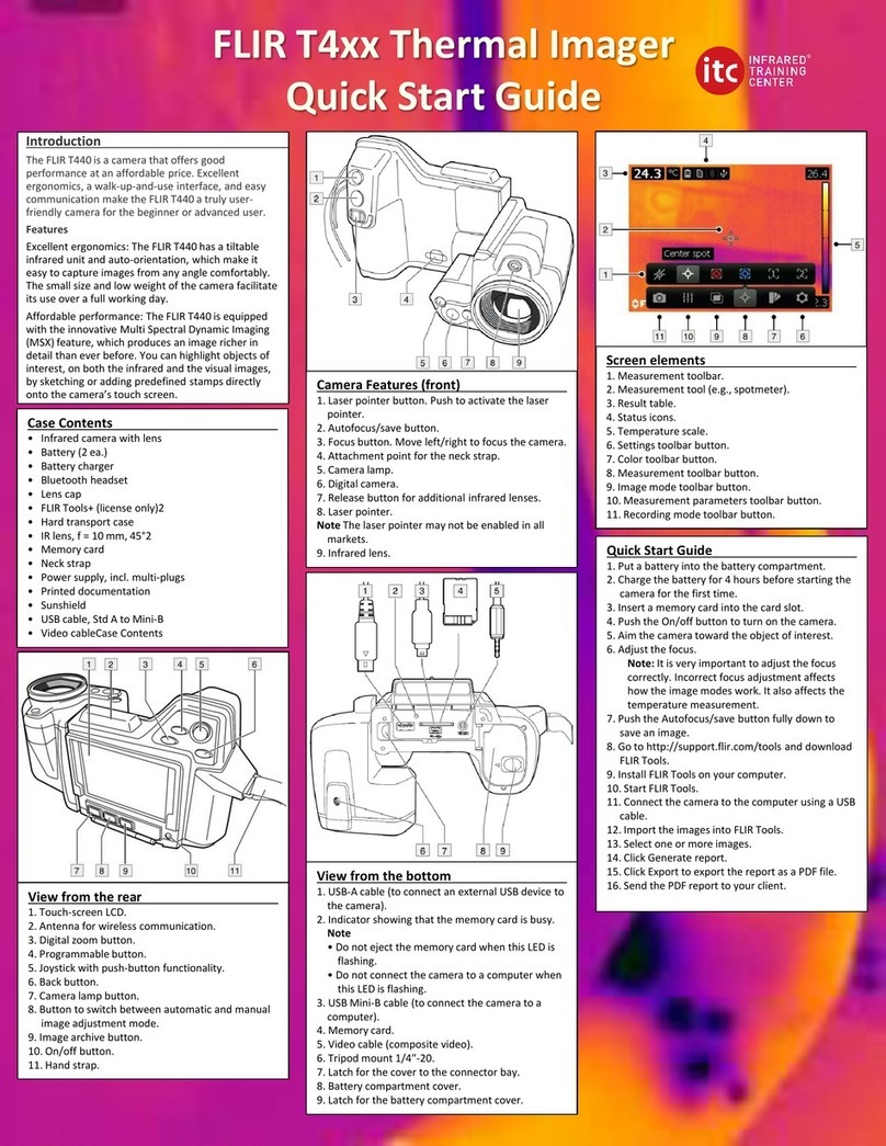
FLIR Thermal MSX Videoscope Kit User manual

USER MANUAL
Thermal MSX®
Videoscope Kit
Kit no. VS290–32


USER MANUAL
Thermal MSX® Videoscope
Kit
#NAS100060; r. AA/71942/71942; en-US iii


Advisories
1
1.1 Copyright
©2020 FLIR Systems, Inc. All rights reserved worldwide.
No parts of the software including source code may be reproduced, transmit-
ted, transcribed or translated into any language or computer language in any
form or by any means, electronic, magnetic, optical, manual or otherwise,
without the prior written permission of FLIR Systems.
The documentation must not, in whole or part, be copied, photocopied, repro-
duced, translated or transmitted to any electronic medium or machine-read-
able form without prior consent, in writing, from FLIR Systems. Names and
marks appearing on the products herein are either registered trademarks or
trademarks of FLIR Systems and/or its subsidiaries. All other trademarks,
trade names or company names referenced herein are used for identification
only and are the property of their respective owners.
1.2 Quality Assurance
The Quality Management System under which these products are developed
and manufactured has been certified in accordance with the ISO 9001 stand-
ard. FLIR Systems is committed to a policy of continuous development; there-
fore, we reserve the right to make changes and improvements on any of the
products without prior notice.
1.3 Documentation
To access the latest manuals and notifications, go to the Download tab at:
https://support.flir.com. It only takes a few minutes to register online. In the
download area you will also find the latest releases of manuals for our other
products, as well as manuals for our historical and obsolete products.
1.4 Disposal of Electronic Waste
As with most electronic products, this equipment must be disposed
of in an environmentally friendly way, and in accordance with existing
regulations for electronic waste. Please contact your FLIR Systems
representative for more details.
#NAS100060; r. AA/71942/71942; en-US 1

Introduction
2
Thank you for selecting the VS290–32 kit. The kit includes the VS290–00 Vid-
eoscope Display and the VSC-IR32 Thermal MSX® Rectangular Probe.
The VS290 is the first industrial inspection Videoscope with Thermal, Visual,
and MSX technology. The VS290 is a rugged, high quality, and reliable visual
inspection instrument that improves productivity and reduces diagnostic time
for facility diagnostics, utilities, manufacturing, public safety, and inspection
service industries.
2.1 Product Features
• 160 x 120 IR imaging resolution with MSX® (Multi-Spectral Dynamic
Imaging).
• Side-view probe (2 m) with flexible points and low-profile, rectangular cam-
era tip.
• 14℉to 752℉(-10℃to 400 ℃) temperature range.
• 57° x 44° field of view (FOV)
• Automatic hot/cold spotting and Isotherm (color) alarms.
• Text annotations (TCF).
• CAT IV 600 V safety rating.
• IP67 rated camera tip (IP54 rated base unit and probe).
• LED worklight.
• Longer than five (5) hours of battery operation on one charge.
2.2 Supplied Items and Accessories
The VS290–32 KIT includes the following:
• Videoscope display
• Thermal MSX camera and probe tube with flexible points
• Li ion rechargeable batteries (2)
• Battery charger (two bays)
• AC power supply
• USB-C cable
• SD card
• Software: License card for ‘FLIR Thermal Studio Standard’, 1 Year
Subscription
• Wrist strap
• Hard-shell carry-case for all items
• Printed Quick Start and Warranty documentation
#NAS100060; r. AA/71942/71942; en-US 2

Introduction
2
2.3 2–10 EXTENDED WARRANTY
To activate the extended 2–10 warranty, please register your product within 60
days of purchase. Otherwise, the standard one-year warranty will be in effect
from date of purchase. The 2–10 warranty covers parts and labour for the
camera for 2 years and coverage of the detector for 10 years. Register your
product at https://support.flir.com/prodreg.
#NAS100060; r. AA/71942/71942; en-US 3

Safety
3
3.1 Safety Notes
• Before operating the device, you must read, understand, and follow all in-
structions, dangers, warnings, cautions, and notes.
• FLIR Systems reserves the right to discontinue models, parts or accesso-
ries, and other items, or to change specifications at any time without prior
notice.
• This product conforms to UL STD 61010-1 and is certified to CSA STD
C22.2, no. 61010-1.
WARNING
• Do not operate the device if you do not have the correct knowledge. Incorrect operation
of the device can cause damage and injury to persons.
• Do not use the device if it show signs of damage. Injury to persons can occur.
• Be careful working near voltages > 25 V AC or 35 V DC. There is a risk of shock from
these voltages. Injury to persons can occur.
CAUTION
Battery Safety
Do not incinerate or disassemble batteries. Batteries can explode or otherwise release
toxic materials.
Do not short circuit batteries, this may cause burns.
Attention. Ne pas incinérer ni démonter les piles. Les batteries peuvent exploser
ou libérer des matières toxiques.
Ne court-circuitez pas les piles, cela pourrait provoquer des brûlures.
#NAS100060; r. AA/71942/71942; en-US 4

Safety
3
WARNING
FCC Warnings. Applicability: Class B digital devices.
This equipment has been tested and found to comply with the limits for a Class B digital
device, pursuant to Part 15 of the FCC Rules. These limits are designed to provide reason-
able protection against harmful interference in a residential installation. This equipment
generates, uses and can radiate radio frequency energy and, if not installed and used in
accordance with the instructions, may cause harmful interference to radio communications.
However, there is no guarantee that interference will not occur in a particular installation. If
this equipment does cause harmful interference to radio or television reception, which can
be determined by turning the equipment off and on, the user is encouraged to try to correct
the interference by one or more of the following measures:
• Reorient or relocate the receiving antenna.
• Increase the separation between the equipment and receiver.
• Connect the equipment into an outlet on a circuit different from that to which the receiver
is connected.
• Consult the dealer or an experienced Radio / TV technician for help.
Unlicensed band: This device complies with Part 15 of the FCC Rules. Operation is subject
to the following two conditions: (1) this device may not cause harmful interference, and (2)
this device must accept any interference received, including interference that may be
cause by unintended operation.
(15.21): Changes or modifications to this unit not expressly approved by the party respon-
sible for compliance could void the user authority to operate the equipment.
CAUTION
• Do not point the infrared camera at strong energy sources, such as the sun, as this can
have an undesirable effect on the camera accuracy and can cause camera damage.
• Use caution when cleaning the camera lens as the lens has a protective coating that is
easily damaged.
• Do not use excessive force when cleaning the camera lens. Damage to the protective
lens coating can occur.
NOTE
The encapsulation rating is only applicable when all the openings on the camera are sealed
with their correct covers, hatches, or caps. This includes the compartments for data storage,
batteries, and connectors.
#NAS100060; r. AA/71942/71942; en-US 5

Product Description
4
4.1 Videoscope Base Unit Description
Figure 4.1 Base Unit Description
1. Camera display
2. Image and video Gallery button
3. LED worklight button
4. Navigation Pad. Menu button (centre) and navigation buttons (outer ring)
5. Return button (exit a menu)
6. Power button (long press)
7. USB connector and memory card compartment
8. Collar screw locks probe to VS290
9. Probe connector
10. Probe tube
11. Image and video capture trigger
12. Handle grip
13. Battery in battery compartment
#NAS100060; r. AA/71942/71942; en-US 6

Product Description
4
4.2 Control Buttons
The four control buttons and navigation pad are explained below.
4.2.1 Power Button
Long press the power button to switch the instrument ON or OFF.
4.2.2 Return Button
Press the Return button to exit or move backward in the programming menu.
4.2.3 Gallery Button
Press the Gallery button to access the stored images and video. Press the
Return button to exit the gallery.
4.2.4 Worklight Button
Press the Worklight button to switch the probe tip light ON or OFF.
4.2.5 Navigation Pad
Figure 4.2 Navigation Pad. Menu button (centre) and outer navigation buttons (left/right, up/
down).
Press the centre button to open the main menu and use it in the menus to
make selections. Use the outer navigation buttons to move up/down and left/
right in the program menus.
#NAS100060; r. AA/71942/71942; en-US 7

Product Description
4
4.3 Top Compartment
Ope the top flap to access the USB connector and the SD card slot.
Figure 4.3 Accessing the USB connector and SD card in the top compartment.
4.4 Rectangular Probe (VSC-IR32)
Figure 4.4 Camera lenses and worklight.
1. Thermal camera lens
2. Digital camera lens
3. LED worklight
4. Connector: Probe tube to probe tip
5. Probe tube
#NAS100060; r. AA/71942/71942; en-US 8

Product Description
4
4.5 Display Description
Figure 4.5 Videoscope display.
1. Battery status
2. USB active
3. Worklight active
4. Cross-hairs. Target a surface spot to measure its temperature. See Sec-
tion 7.6, Measurements Menu, for additional cross-hairs functionality.
5. Highest temperature sensed in the current camera image.
6. Range of the selected display color palette. In the Above/Below Alarm
Color modes, alarm alerts are represented here.
7. Lowest temperature sensed in the current camera image.
8. Main menu icons.
9. Thermal MSX alignment sliders. Vertical and horizontal sliders are used to
align the super imposed thermal and digital camera images. The horizon-
tal slider is obstructed in the image above.
10. Temperature reading of targeted spot. In Hot/Cold Spot modes, this area
will show the MAX or MIN temperature (see Section 7.6, Measurements
Menu, for more).
#NAS100060; r. AA/71942/71942; en-US 9

Battery Charging and Use
5
The VS290–32 kit is supplied with two high capacity batteries and a stand-
alone two-bay charger. To charge batteries, place them in the charger and
plug the charger into an AC receptacle. The LED indicators on the charger
flash while a battery is charging and glow steadily when fully charged. It may
require up to 2 hours for a full charge if a battery is completely drained.
You can also charge a battery while it is in the camera by connecting the
VS290 directly to an AC wall charger (5V / 2A) using the supplied USB cable.
The USB connector is located in the VS290 top compartment. See illustration
below.
Figure 5.1 Charging a battery while it is installed in the instrument.
Once charged, place a charged battery into the battery compartment and long
press the power button to power the instrument. If an error message ap-
pears informing that the battery voltage is low, charge the battery immediately.
#NAS100060; r. AA/71942/71942; en-US 10

Quick Steps
6
These steps are provided to provide a simple overview. Please read the entire
User Manual before putting these devices into professional operation.
1. Insert a fully charged battery into the VS290 handle.
2. Long press the power button to power up.
3. When powered, the VS290 displays a camera image and several function
indicators, dependant on the configuration of the instrument.
Figure 6.1 Viewing a camera image.
4. Carefully position the probe into the area to be examined and view the
camera image on the display. Short press the worklight button to switch
the light on/off.
Figure 6.2 Insert the probe into the test area.
#NAS100060; r. AA/71942/71942; en-US 12

Quick Steps
6
5. To select an image mode, press the Menu button (centre), scroll to the Im-
age Mode icon and press Menu again. Use the navigation buttons to se-
lect Thermal MSX, Thermal, or Digital camera; press Menu to confirm.
6. The cross-hairs allow you to target and measure the surface temperature
of a spot. The measurement is shown digitally (upper left). The thermal
scale for the current image is shown on the right edge of the display.
7. To capture an image or to stop/start a video, pull and hold the trigger.
Press the Gallery button to view stored images and videos. Images/vid-
eos can be transported to a PC via USB.
#NAS100060; r. AA/71942/71942; en-US 13

Programming Menus
7
7.1 Basic Navigation
Press the Menu button (centre) to open the main menu and the sub-menus.
Use the navigation buttons to scroll left/right and up/down. Use the Menu but-
ton (centre) to confirm a selection; press the Return button to exit a menu.
7.2 Main Menu
The main menu options are: 1. Image Rotation, 2. Image Mode, 3. Color, 4.
Measurement, 5. Temperature Scale, and 6. Settings.
7.3 Image Rotation Menu
Figure 7.1 Accessing the Image Rotation mode.
Press Menu on the Image Rotation icon and use the navigation buttons to
select 90° rotation or horizontal/vertical flip of the camera image. Press Menu
to confirm.
Figure 7.2 Selecting 90° Rotation or Vertical/Horizontal Flip.
#NAS100060; r. AA/71942/71942; en-US 14

Programming Menus
7
7.4 Image Mode Menu
Figure 7.3 Accessing the Image Mode menu.
Press Menu on the Image Mode icon and use the navigation buttons to
select: Digital, Thermal, Thermal MSX, or Alignment Distance.
Thermal MSX (Multi-Spectral Dynamic Imaging) is an enhancement that im-
proves image clarity by embossing visual scene details on the thermal image,
providing added context to accurately target potential issues. The MSX Align-
ment Distance option allows you to fine tune the embossed visual scene de-
tails using the vertical and horizontal sliders. See Figure 7.5 below.
Figure 7.4 Selecting the Thermal MSX, Thermal only, and Digital Camera modes.
Figure 7.5 Select the Thermal MSX mode and then the Alignment Distance option. Use the
sliders (left side and bottom of the display) to align the Digital Camera image with the Thermal
image. Use the left/right and up/down arrow buttons to make the adjustments.
#NAS100060; r. AA/71942/71942; en-US 15

Programming Menus
7
7.5 Color Palette Menu
Figure 7.6 Accessing the Color Palette mode.
To select a display color palette, press Menu on the Color icon and use
the navigation arrows to scroll. Press Menu when the desired color palette is
selected (Iron, Rainbow, Gray, Above Alarm, or Below Alarm).
In the Above/Below Alarm modes (known as ‘Isotherms’), you select a high
alarm set point (for Above Alarm mode) and a low alarm set point (for Below
Alarm mode). The colorations in the thermal image indicate the sections of
the test area that exceed the set point limit. Use the arrow buttons to set the
temperature limits (the set point is shown on the bottom of the display). The
vertical color bar graph on the right side of the display indicates the degree to
which the alarm set point is exceeded. See Section 9, Isothermal Color
Alarms, for more.
Figure 7.7 Selecting a Color palette or an Isotherm Alarm (Above and Below) mode.
#NAS100060; r. AA/71942/71942; en-US 16
This manual suits for next models
1
Table of contents
Other FLIR Thermal Camera manuals

FLIR
FLIR ONE PRO LT User manual

FLIR
FLIR VS290-2x User manual

FLIR
FLIR FLIR H Series User manual

FLIR
FLIR D-Series C User manual

FLIR
FLIR G Series User manual

FLIR
FLIR 432-0012-04-00 User manual

FLIR
FLIR E series User manual

FLIR
FLIR PatrolIR PTZ User manual

FLIR
FLIR ThermaCAM P45 User manual

FLIR
FLIR M-Series User manual
Popular Thermal Camera manuals by other brands

PeakTech
PeakTech 5610 Operation manual

Chauvin Arnoux
Chauvin Arnoux C.A 1954 DiaCAm 2 quick start guide

Satir
Satir UMTI user manual

International Safety Instruments
International Safety Instruments Surveyor Owner's operation manual

Hikmicro
Hikmicro HM-TS03-15XF quick start guide

TESTO
TESTO 870 instruction manual