Flo CoRe+ User manual

Anchor Installation Guide
TM
TM

Table of Contents
1. Introduction ....................................................................................................................................... 3
2. Pedestal Anchor ............................................................................................................................... 3
2.1. Anchor Specifications ............................................................................................................. 3
2.2. Concrete Base Specifications ............................................................................................... 4
2.2.1. Dimensions ............................................................................................................................. 4
2.2.2. Conduit Positioning .............................................................................................................. 4
3. Installation ......................................................................................................................................... 7
3.1. Cascading Single Station Pedestals .................................................................................... 7
3.2. Cascading Dual Side-by-Side Station Pedestals ............................................................... 7
3.3. Cascading Back-to-Back Station Pedestals – Charging Stations on Front and Back 8
3.4. Cascading Back-to-Back Station Pedestals – Charging Stations on the Sides .......... 8
4. Copyright and Liability ..................................................................................................................... 9

1. Introduction
This guide provides instructions for installing the pedestal anchor for the CoRe+TM and
CoRe+ MAXTM.
2. Pedestal Anchor
The pedestal is designed to be mounted on a prefabricated anchor with free space in the
center that has conduit openings to allow for the passage of the power supply cables. The
sections below show the installation details. Certain types of installations may require a
concrete base. Refer to the section below for more information.
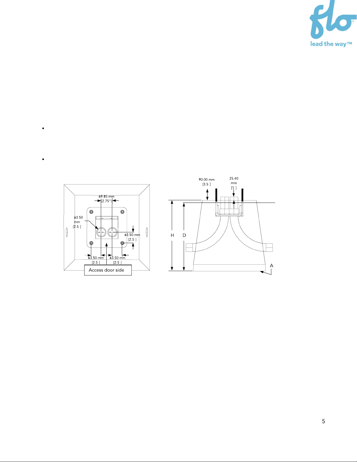
2.1. Anchor Specifications
The installer can use a FLOTM prefabricated anchor (part number: ACAN0001 or C+V1-
ANCHOR) or make their own using 304.8 mm (12”), 12.7 mm (½”) diameter threaded rods
spaced according to the image below.
Prefabricated
anchor
Threaded rod

2.2. Concrete Base Specifications
The concrete base can be prefabricated or made on site using a concrete formwork. The
dimensions and conduit positioning must be determined based on the environment and
layout configuration.
2.2.1. Dimensions
The concrete base’s height (H), depth in the ground (D), and surface area (A) must be
determined according to the soil type and the freeze/thaw specifications of the installation
area. Use an appropriate electrical conduit with a maximum diameter of 50.8 mm (2’’) to
position the electrical cables in the center of the anchor. The pedestal base opening has
been sized to accept 2 PVC conduits up to 50.8 mm (2’’) in diameter each, whether in side-
by-side or back-to-back configuration.
2.2.2. Conduit Positioning
The conduit positioning in the concrete base will vary according to the charging station
configuration.
Side-by-Side Conduit Positioning (Compatible for both CoRe+ and CoRe+ MAX
pedestals)
Use for Single, Dual Side-by-Side, and Back-to-Back (Stations on Back and Front) charging
station installations (see sections 3.3.1 to 3.3.3).
The conduit positioning should follow the guidelines below:
The conduits should be off centered toward the door, with the outside of the
conduits at a minimum distance of 32 mm (1.25’’) from the center of the anchor
pins.
The 2 conduits must be placed side by side and centered between the anchor
pins, which are located on each side of the pedestal access door.
"
" "
Ø
"
""

Back-to-Back Conduit Positioning (Compatible with CoRe+ MAX pedestals only)
Use these instructions for the Back-to-Back (Stations on the Sides) charging station
installation (see section 3.3.4)
The conduit positioning should follow the guidelines below:
The conduits should be off centered toward the door, with the outside of the
conduits at a minimum distance of 32 mm (1.25’’) from the center of the anchor pins.
The 2 conduits must be placed back-to-back and be centered between the anchor
pins, which are located on each side of the pedestal’s access door.
"
"
"
"
Ø
"
""

3. Installation
The pedestal base and conduit installation vary according to the charging station
configurations.
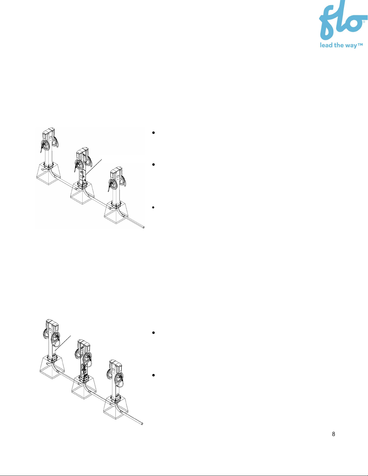
3.1. Cascading Single Station Pedestals
Cascading single station pedestals have the following characteristics:
When a single charging station head is mounted on a
pedestal, it should always be facing the parking
space it is serving.
When the head is facing the parking space, the
pedestal access door must be at the back of the
charging station.
To have the access door on the back side of the
charging station, the conduit configuration must be
side-by-side, as shown.
3.2. Cascading Dual Side-by-Side Station Pedestals
Cascading dual side-by-side station pedestals have the following characteristics:
When 2 charging station heads are mounted side by
side on a pedestal, they should always be facing the
parking space they are serving.
When the heads are facing the parking space, the
pedestal access door must be at the back of the
charging station.
To have the access door on the back side of the
charging station, the conduit configuration must be
side-by-side, as shown.
Access door side
Access door side
3.3. Cascading Back-to-Back Station Pedestals –
Charging Stations on Front and Back
Cascading dual back-to-back station pedestals with charging stations on the front and
back have the following characteristics:
When two charging station heads are placed in the
front and back of the pedestal, they should be facing
the parking space it is serving.
When the heads are facing the parking space, the
access doors of the pedestals must be placed on
the same side as one of the charging stations, facing
one of the parking spaces.
To have the access door on the same side of a
charging station, the conduit configuration must be
side-by-side, as shown.
3.4. Cascading Back-to-Back Station Pedestals –
Charging Stations on the Sides
Compatible with CoRe+ MAX pedestals only
Cascading dual back-to-back station pedestals with charging stations on the sides have
the following characteristics:
When the charging station heads are positioned on
the side of the pedestal, the access door of the
pedestal must be placed on the same side of a
charging station.
To have the access door on the same side of a
charging station, the conduit configuration must be
back-to-back, as shown.
Access door side
Access door side

4. Copyright and Liability
Document name: FLO_CoRe+ and CoRe MAX_Anchor Installation Guide_V.1.0.0_2023-01-
16_CA_US_EN
Document ID: PRFM0003
FLO CA: © 2016-2023 Services FLO Inc., All rights reserved. FLO, the FLO logo, LEAD THE WAY,
and TRACEZ LA VOIE are trademarks of Services FLO Inc. ADDÉNERGIE is a trademark of
AddÉnergie Technologies Inc. used under license by Services FLO Inc.
FLO US: © 2016-2023 FLO Services USA Inc., All rights reserved. FLO, the FLO logo, LEAD THE
WAY, and TRACEZ LA VOIE are trademarks of Services FLO Inc. used under license by FLO
Services USA Inc. ADDÉNERGIE is a trademark of AddÉnergie Technologies Inc. used under
license by FLO Services USA Inc.
This document is provided as a general instruction guide. All pictures shown are for
illustration purposes only. Actual stations may vary in size or due to product enhancements,
in which case additional steps may be required. AddÉnergie Technologies Inc. and its
subsidiaries (“AddÉnergie”) reserve the right to alter this document and any product
offerings and specifications at any time without notice and AddÉnergie does not guarantee
that that this version of the document is current. It is your responsibility to comply with all
applicable laws, including those related to accessibility, zoning, and to exercise due
diligence when conducting an installation or using this product. Careless installation or use
may result in injury or product damage. To fullest extent permitted by applicable laws,
AddÉnergie disclaims any liability for personal injury or property damage resulting from the
installation or use of this product.

Other manuals for CoRe+
5
This manual suits for next models
1
Table of contents


