16
15
2. Solar DLB Model Selection
Model
Operating Mode
BCP-DLB-11M BCP-DLB-13M
PV
Night Automatic
Full Speed Mode
PV
PV to Normal
/Normal to PV √ √
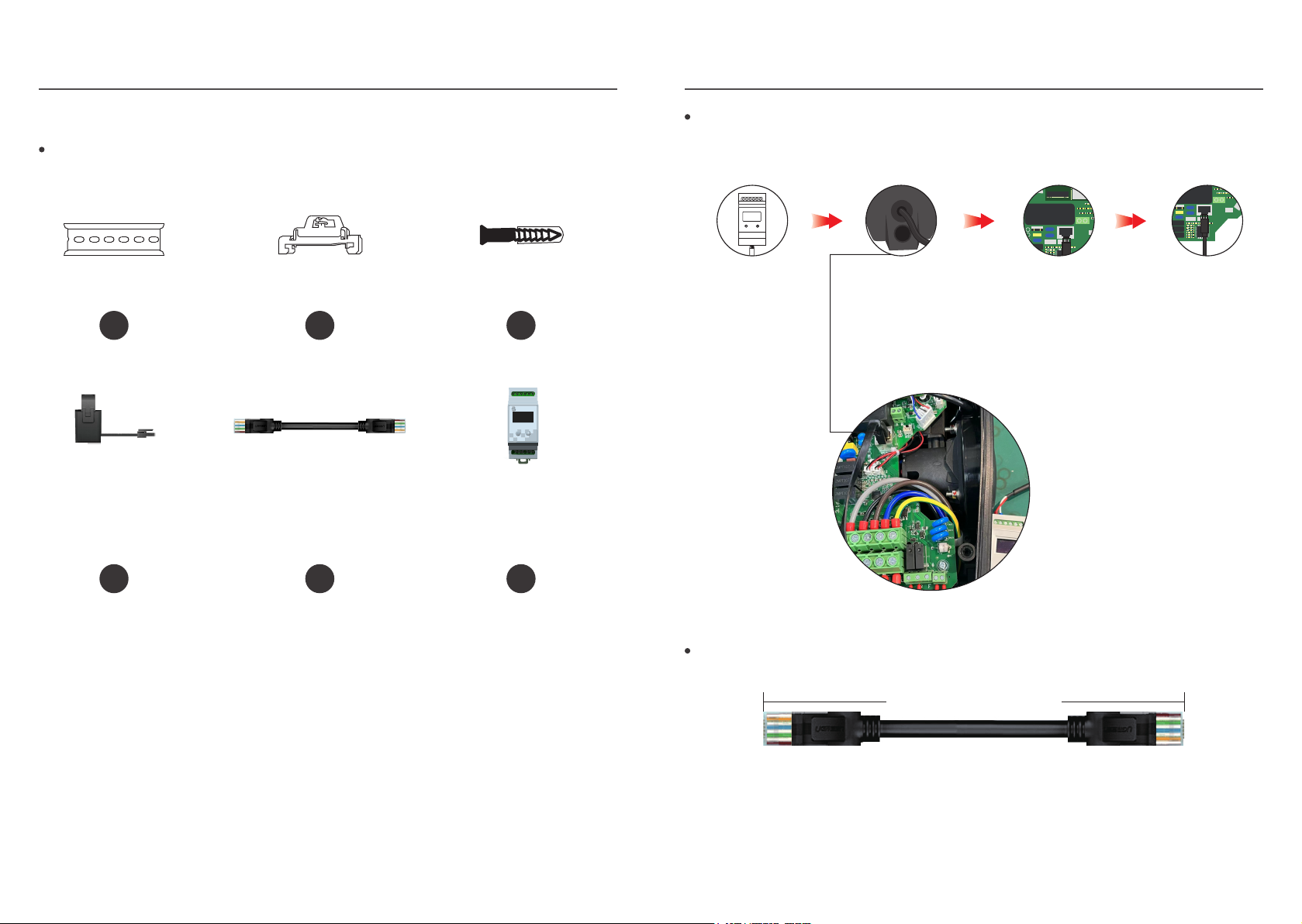
Number of Current
Transformers 26
OLED
Display
More than 300M
Distance between
DLB box and RV
charger suppert
Current
Transformer
Default Length
1.5m(Can be customized up to 15 meters)
Installation Rail installation/Screw fixing
Communication RS485(Use RJ45 interface to connect with network)
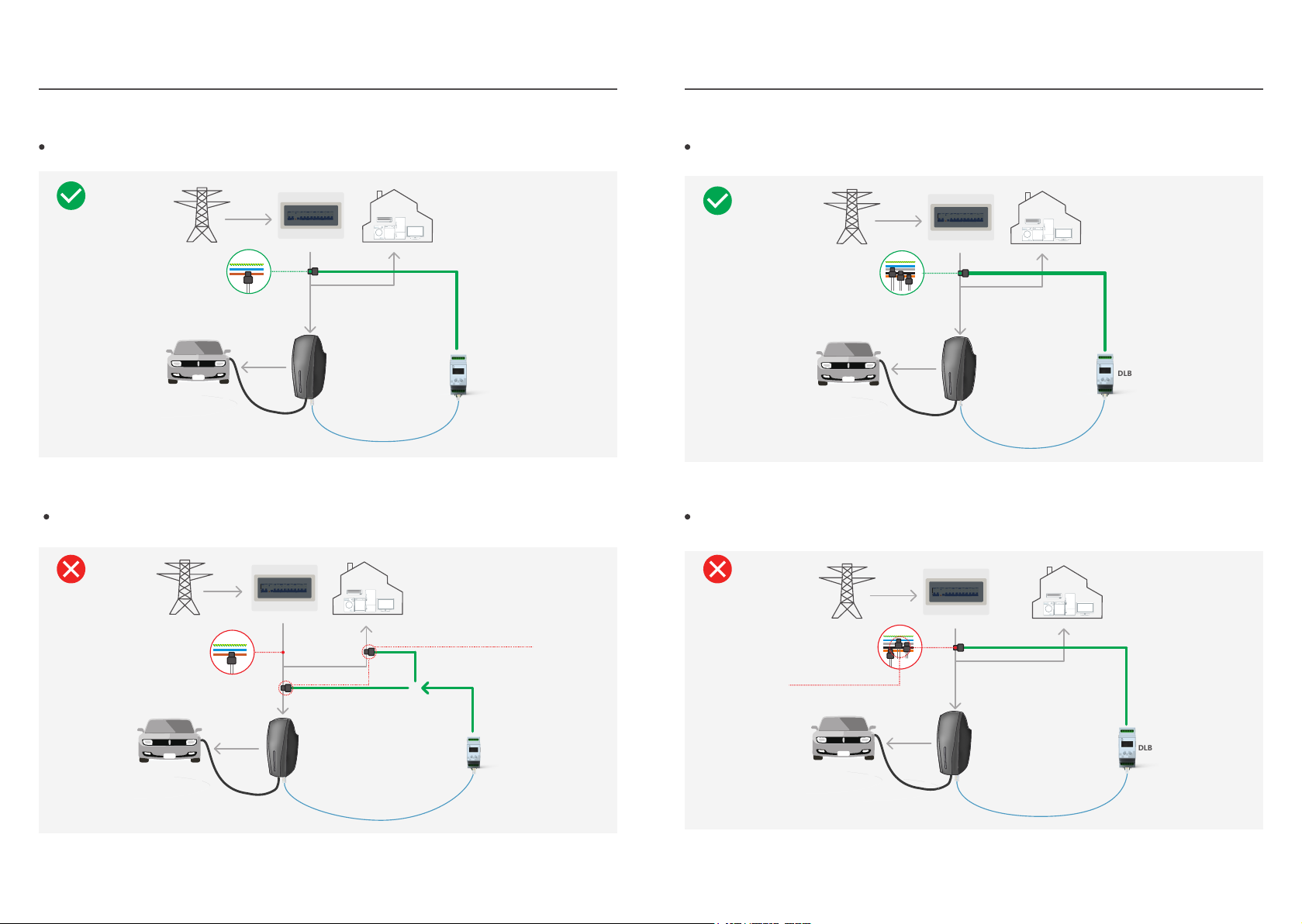
In this mode, once the household load continues to increase and the photovoltaic power
generation is not enough to maintain the minimum current of the EV charger, it will stop
charging to avoid using too much grid power (this power depends on the set value). When the
EV charger has enough current (eg 10A), restart charging.
Extreme Mode
√ √
√ √
What is PV Extreme Mode?
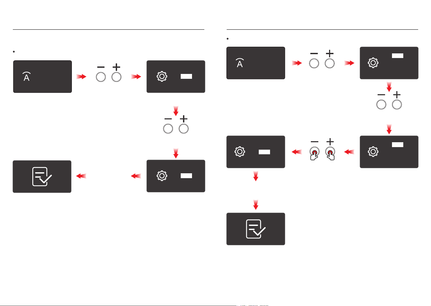
We can set the Night Automatic Mode through APP.
How to Active Night Automatic Full Speed Mode?
What is Night Automatic Full Speed Mode?
In this mode the EV charger will remain charged at full speed (Pm20:00- Am6:00). Note: The
coin cell battery is not installed in the original factory charger (the battery is installed by
yourself if required), the EV charger will lose this configuration after restarting, and it needs to
reconnect the APP to configure it.
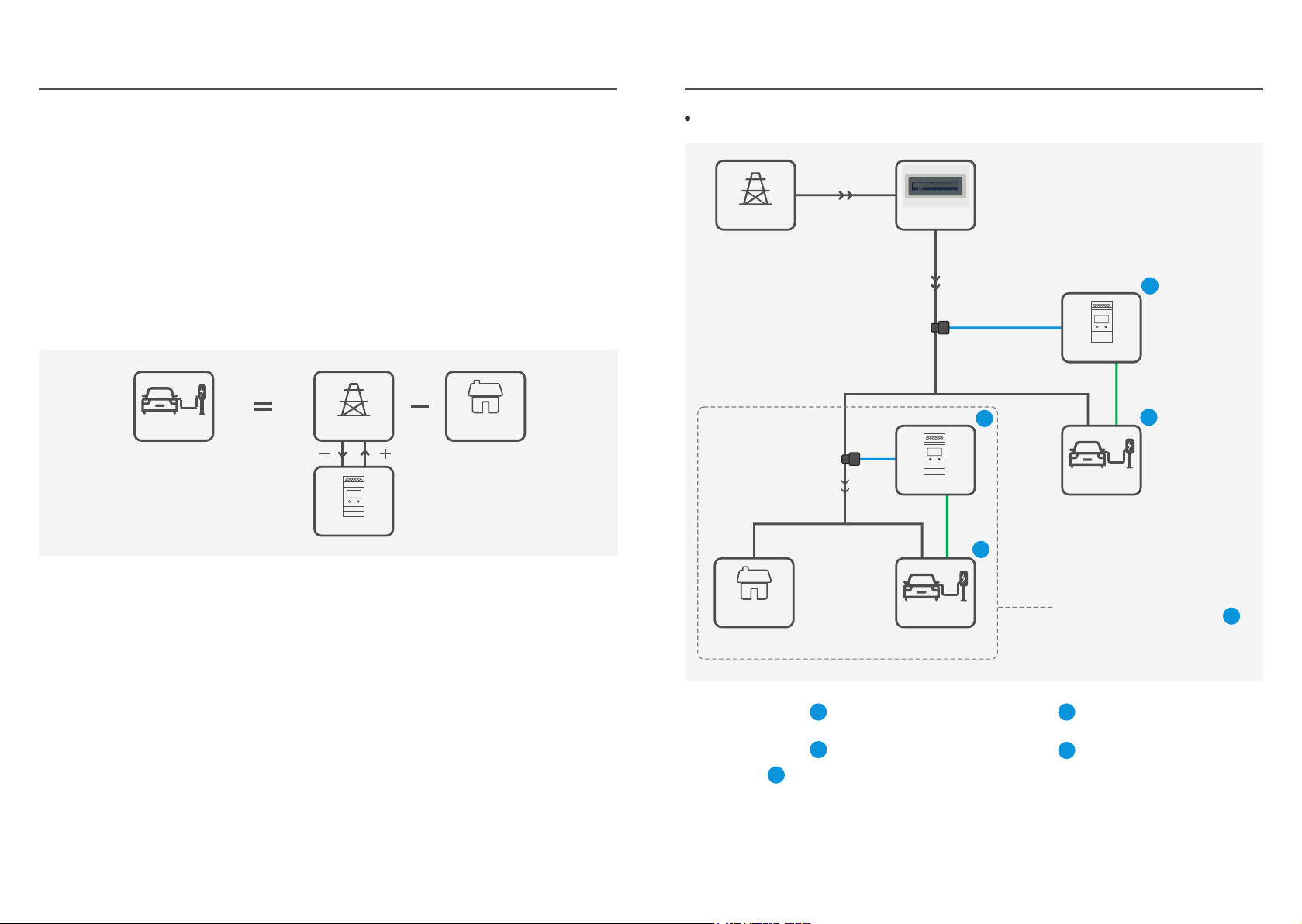
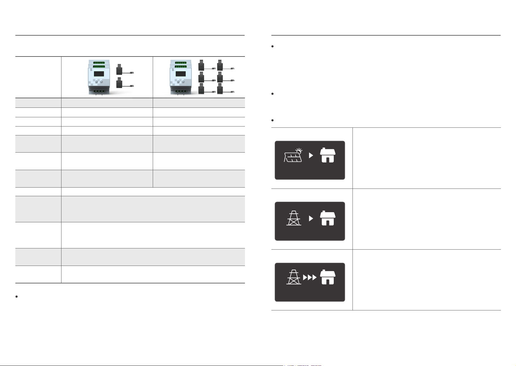
Pure PV Mode
The EV charger in the pure PV mode will control its own
charging current as much as possible, so that the actual
input value of the grid current is as close as possible to
0A.
Hybrid Mode
The EV charger in hybrid mode will control its own
charging power to keep the grid input power as close as
possible to the DLB setting.
Full Speed Mode
When the EV charger is working in full speed mode, the
DLB will no longer limit the charging current of the EV
charger, and the charging pile will use the maximum
current supported for charging.
Full Speed Mode
Hybrid Mode
Pure PV Mode
4.6kW
Introduction to the three modes of DLB
Solar DLBSolar DLB
Phase Single Phase Three Phase