Florence versatile 4C Depot User manual

INSTALLATION MANUAL
versatile™ 4C Depot
Stand-alone Cabinet

Page 2 of 16 4C Depot Installation Manual—206731—Rev C www.florencemailboxes.com
GENERAL INFORMATION AND ADVISORIES
ATTENTION!
CAUTION -- Transportation and Handling
• Florence 4C Depot units are heavy. Use caution when lifting and carrying to avoid injury.
• Lay boxes flat. Do not stand on end as box could fall over and cause injury.
CAUTION -- Installation
• Florence 4C units are heavy. Do not stand 4C units up without support to prevent tipping.
• Pinch hazard exists when placing cabinets next to each other. Keep fingers and hands
clear to avoid injury.
• Florence 4C units are also front-heavy when the master doors are open. Units must be
braced or held in place until secured to the concrete. Failure to do so could result in
serious injury.
GENERAL INFORMATION AND ADVISORIES � � � � � � � � � � � � � � � � � � � � � � � � � � � � � � � � � � � � � � � �2
ASSOCIATED TECHNICAL DOCUMENTS � � � � � � � � � � � � � � � � � � � � � � � � � � � � � � � � � � � � � � � � � �2
4C DEPOT OVERVIEW � � � � � � � � � � � � � � � � � � � � � � � � � � � � � � � � � � � � � � � � � � � � � � � � � � � � �3
SUGGESTED TOOLS � � � � � � � � � � � � � � � � � � � � � � � � � � � � � � � � � � � � � � � � � � � � � � � � � � � � � �4
HARDWARE LIST � � � � � � � � � � � � � � � � � � � � � � � � � � � � � � � � � � � � � � � � � � � � � � � � � � � � � � � �4
UNPACK THE 4C DEPOT� � � � � � � � � � � � � � � � � � � � � � � � � � � � � � � � � � � � � � � � � � � � � � � � � � � �5
PREPARATION AND INITIAL PLACEMENT � � � � � � � � � � � � � � � � � � � � � � � � � � � � � � � � � � � � � � � � � �6
ANCHOR THE 4C DEPOT TO CONCRETE � � � � � � � � � � � � � � � � � � � � � � � � � � � � � � � � � � � � � � � � � 10
FINISH INSTALLATION � � � � � � � � � � � � � � � � � � � � � � � � � � � � � � � � � � � � � � � � � � � � � � � � � � � � 11
4C MAILBOX ACTIVATION BY USPS � � � � � � � � � � � � � � � � � � � � � � � � � � � � � � � � � � � � � � � � � � � � 11
© 2020 Florence Corporation. All rights reserved.
TABLE OF CONTENTS
ASSOCIATED TECHNICAL DOCUMENTS
`206362—4C Mailbox Installation Manual
`206367—4C Mailbox Maintenance Manual
`206731-001—4C Depot Stand-alone Cabinet Foundation Plan
APPENDIX A: INSTALLING 4C MAILBOX INTO DEPOT CABINET� � � � � � � � � � � � � � � � � � � � � � � � � � � � 12

Page 3 of 16
4C Depot Installation Manual—206731—Rev Cwww.florencemailboxes.com
4C DEPOT OVERVIEW
• The 4C Depot consists of a stand-alone cabinet with a 4C mailbox installed.
• 4C Depot cabinets are of aluminum construction with a durable powdercoat finish on all
exposed exterior surfaces.
• Each Depot cabinet has four (4) adjustable leveling feet for installation on uneven surfaces.
• Each Depot cabinet has a removable lower-front panel to allow easy access for leveling and
anchoring the cabinet to a concrete pad.
Removable
lower-front panel
4C Depot
cabinet
4C
mailbox
Leveling
feet

Page 4 of 16 4C Depot Installation Manual—206731—Rev C www.florencemailboxes.com
SUGGESTED TOOLS
Unloading/Unwrapping:
• Tin snips
• Dolly
• Straps
Basic Installation:
• 2-ft level
• Hammer drill
`7/16” masonry bit — >4” length
required
• Cordless drill/driver w/clutch
• #2 Phillips driver bit
• SAE open end wrench or socket set (9/16”
and 3/4” required)
General:
• Gloves
• Safety glasses
• Steel toed shoes
• Shop vacuum
• Broom
• Waterbased cleaner, such as “Simple
Green™”
• Soft chamois
HARDWARE LIST
K214164 hardware kit consisting of the following items is included:
(1) K214163 kit which contains:
(15) 206727 - 10-32 x 1/2”, Phillips-head
self-tapping screw, Stainless Steel
(1) 206729 - 11/64” diameter drill bit,
HSS
(1) 206730 - #2 square-tip 1/4” hex-
shank insert driver bit, Steel
(4) 206725 - 1/2” x 3” hex-washer-head
Tapcon® anchor bolt, Steel
K65734 kit (included only with a 4C Depot with no 4C module installed) which contains:
(22) 65734 - 8-18 x 1 1/4” pan-head T20 Torx
screws, zinc-plated Steel

Page 5 of 16
4C Depot Installation Manual—206731—Rev Cwww.florencemailboxes.com
UNPACK THE 4C DEPOT
If you have purchased a 4C Depot free-standing cabinet with no 4C mailbox installed, go to
“APPENDIX A: INSTALLING 4C MAILBOX INTO DEPOT CABINET” on p. 12 for instructions to
install your 4C mailbox into the cabinet.
1 . Each 4C Depot, with 4C mailbox installed, will arrive packaged in a single cardboard carton
held together by banding.
2 . Cut the banding and carefully remove the packaging from the 4C Depot.
3 . A package containing the hardware needed to install the 4C cabinet is inside a
compartment near the bottom of the 4C mailbox unit (refer to “HARDWARE LIST” on p.
4).
4 . Ensure the leveling feet on the 4C Depot cabinet are adjusted up all the way.
5 . Carefully move the 4C Depot to the installation/staging area.
IMPORTANT NOTE:
When accepting the shipment from the carrier, inspect, and
make note of, and/or photograph, any noticeable damage
that may have occurred during shipment. Report any
damage found to the freight company.
Be extremely careful not to scratch or damage the
finish on the unit when removing the packaging.
WARNING: 4C Depot with 4C mailbox installed
is heavy. Use two (2) or more people to move
cabinets. Use caution when lifting and carrying.
Failure to do so could result in serious injury.

Page 6 of 16 4C Depot Installation Manual—206731—Rev C www.florencemailboxes.com
PREPARATION AND INITIAL PLACEMENT
1 . Place the 4C cabinet in the desired installation location.
2 . Remove the lower-front panel from the cabinet.
• Use the #2 square-tip 1/4” hex-shank insert
driver bit supplied in the package of
hardware, placed into a cordless driver, to
remove the two (2) screws from the panel.
• Pull the panel out at the bottom and down
from behind the 4C mailbox trim.
square-drive screws

Page 7 of 16
4C Depot Installation Manual—206731—Rev Cwww.florencemailboxes.com
3 . Remove and discard the plastic push-in rivets
which hold the two mounting brackets and two
skirt plates in place inside the lower
compartment of the 4C Depot cabinet.
4 . Remove the two mounting brackets and two
skirt plates from the cabinet, and set them aside
for later installation.
5 . Adjust the leveling bolts down with a 9/16”
wrench until the unit is level.
• You should only have to adjust 3 of the 4 leveling bolts. The leveling bolt that remains
unadjusted is the leveling bolt located in the highest spot on the concrete slab.
• A 2-ft level with a centered bubble across the top, sides, and front ensures the cabinet
is level and plumb. A failure to do this properly will likely cause problems with the 4C
mailbox operation.
temporary
plastic rivets
skirt plates
mounting brackets
Note: A 9/16” wrench is incorporated into
each of the mounting brackets, if you need
them. They can be removed by breaking the
tabs holding them in place.
mounting
bracket
9/16” wrench
leveling feet

Page 8 of 16 4C Depot Installation Manual—206731—Rev C www.florencemailboxes.com
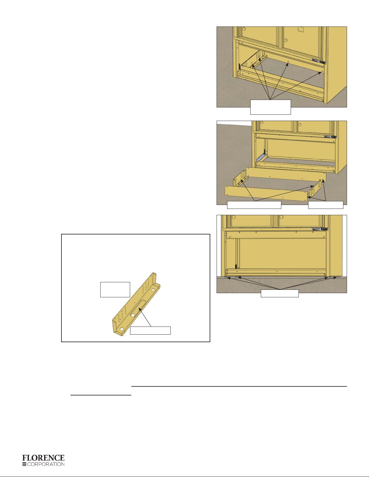
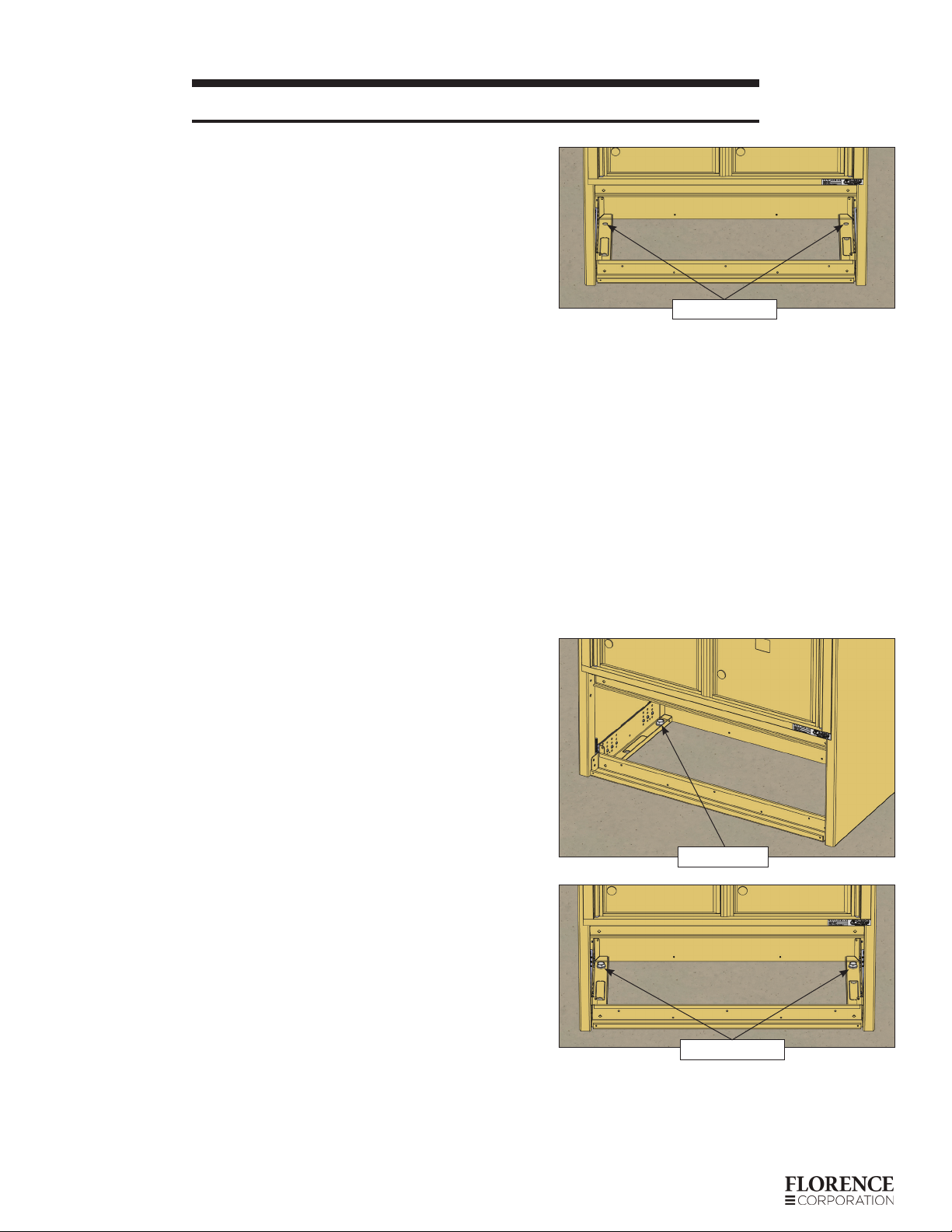
6 . Tighten the jam nuts on all four (4) of the
leveling bolts with a 9/16” wrench to lock the
leveling bolts in their leveled position.
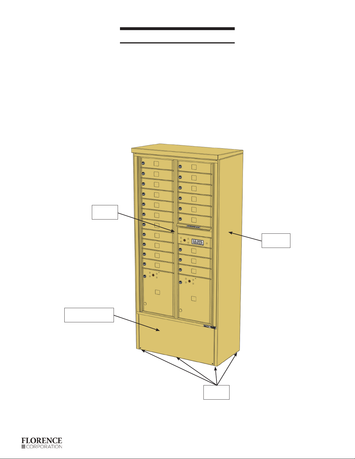
7 . Install the two (2) mounting brackets and two (2)
skirt plates back inside the lower compartment
of the 4C Depot cabinet. The skirt plates close
the gap beneath the leveled cabinet and the
concrete.
A. Rest the mounting brackets on the concrete
pad and position them directly against the
side panel structural tubes.
B. Position the skirt plates between the ends
of the mounting brackets and the front
and back of the cabinet, and pushed down
against the concrete pad.
• Be sure both skirt plates are in place
before drilling the holes in Step C, to
ensure that the mounting brackets are
positioned in proper alignment.
C. Use the 11/64” diameter drill bit (206729)
included in the hardware kit (refer to
“HARDWARE LIST” on p. 4) to drill
through six (6) holes in each mounting
bracket.
• Drill the six holes (one in each column of
holes) that best align with the side panel
structural tube in the side of the cabinet.
• The holes should only be drilled through
the tube wall which is directly against the
mounting bracket (approximately 1/4”
thick).
jam nuts
side panel
structural tube
Front skirt plate removed
for illustration clarity
Be extremely careful not to drill
through the cabinet side panel which
is about 1 1/4” from the mounting
bracket.
Front skirt plate removed
for illustration clarity
Drill thru 6 holes
into structural tube.

Page 9 of 16
4C Depot Installation Manual—206731—Rev Cwww.florencemailboxes.com
D. Secure each mounting bracket to the
cabinet structural tube using six (6) 10-32 x
1/2” self-tapping Phillips-head screws
(206727).
Front skirt plate removed
for illustration clarity
self-tapping screws
Front skirt plate in place

Page 10 of 16 4C Depot Installation Manual—206731—Rev C www.florencemailboxes.com
ANCHOR THE 4C DEPOT TO CONCRETE
1 . With a hammer drill and 7/16” masonry bit, drill
holes through the anchor holes in each end of
the mounting brackets to a depth of 4 inches
into the concrete.
• If you successfully drill all four anchor holes
to full depth, go to Step 6.
• Otherwise, if you can’t apply enough
pressure on the drill to completely drill the
holes while positioned inside the cabinet,
just use the drill to mark the placement of
the holes on the concrete and proceed to
Step 2.
2 . Move the cabinet out of the way to reveal the
drill marks. Finish each hole in the concrete by
drilling to full depth.
3 . Move the cabinet back over the holes drilled
into the concrete.
• You only need to align one hole in one of
the mounting brackets with the appropriate
hole in the concrete.
4 . Install a single Tapcon® anchor bolt (206725)
with an impact driver and 3/4” socket, but do
not tighten all the way.
5 . Rotate/pivot the cabinet around the single
previously installed anchor until the rest of the
holes in the mounting brackets align with the
holes drilled in the concrete.
6 . Install Tapcon® anchor bolts (206725) into all of
the holes with an impact driver and 3/4” socket.
7 . Ensure all anchor bolts are tight.
anchor holes
anchor bolt
anchor bolts

Page 11 of 16
4C Depot Installation Manual—206731—Rev Cwww.florencemailboxes.com
FINISH INSTALLATION
1 . Insert the top of the lower-front panel into the
gap behind the lower 4C mailbox trim and push
the bottom of the panel against the cabinet.
2 . Secure the lower-front panel to the cabinet
using a #2 square-tip 1/4” hex-shank insert
driver bit and the two (2) screws removed at the
start of the installation.
4C MAILBOX ACTIVATION BY USPS
• If the 4C Depot is to be serviced by the US Postal Service, refer to the “4C Mailbox Installation
Manual (206362)” for specific instructions on Arrow Lock installation to activate service to the
mailbox.
• The Arrow lock is installed by USPS Postal Service personnel ONLY.
• Contact your local Post Oce to arrange acquisition and installation of the Arrow lock into the
master access door, the parcel-door, and the hopper-box collection door. (Collection boxes
require a dierent lock than standard 4C mailbox modules.)
Reinstall screws.

Page 12 of 16 4C Depot Installation Manual—206731—Rev C www.florencemailboxes.com
APPENDIX A: INSTALLING 4C MAILBOX
INTO DEPOT CABINET
UNPACK THE 4C DEPOT CABINET
1 . Each 4C Depot cabinet will arrive packaged in a single cardboard carton held together by
banding.
2 . Cut the banding and carefully remove the packaging from the 4C Depot cabinet.
3 . A package containing the hardware needed to install the 4C cabinet, including the
mounting screws to mount the 4C mailbox into the 4C Depot cabinet, is taped inside the
bottom of the cabinet (refer to “HARDWARE LIST” on p. 4).
• All of the included mounting screws in the K65734 hardware kit may not be needed,
depending on the size of the 4C Depot cabinet.
4 . Ensure the leveling feet on the 4C Depot cabinet are adjusted up all the way.
5 . Lay the 4C Depot cabinet on its back on a non-abrasive surface which will protect the
finish on the cabinet.
CAUTION
• Florence 4C units are heavy. Use caution when lifting and carrying to avoid
injury.
• Pinch hazard exists when placing mailbox units into Depot cabinets. Keep
fingers and hands clear to avoid injury.
• 4C Depot with 4C mailbox installed is heavy. Use two (2) or more people to
move cabinets. Use caution when lifting and carrying. Failure to do so could
result in serious injury. Units must be braced or held in place until secured to
the concrete. Failure to do so could result in serious injury.
Be extremely careful not to scratch or damage the
finish on the unit when removing the packaging.

Page 13 of 16
4C Depot Installation Manual—206731—Rev Cwww.florencemailboxes.com
6 . Insert the 4C mailbox module into the front opening of the 4C Depot cabinet, taking care
not to damage the mailbox or the cabinet.
7 . For Double-Wide Florence 4C Modules:
A. Open the right master door until the hold-
open arm engages and install the included
8-18 x 1 1/4” pan-head T20 Torx screws
(65734) in all of the slots along the right-
hand outer frame.
B. Partially open the left master door until the
right master door can be completely closed.
C. Open the left master door until the hold-
open arm engages, and install the included
8-18 x 1 1/4” pan-head T20 Torx screws
(65734) in all of the slots along the left-hand
outer frame.
mounting
screws
mounting
screws

Page 14 of 16 4C Depot Installation Manual—206731—Rev C www.florencemailboxes.com
D. With both the left and right master doors
open and hold-open arms engaged, install
`the included 8-18 x 1 1/4” pan-head T20 Torx
screws (65734) in all of the holes along the
bottom and top frame.
8 . For Single-Wide Florence 4C Modules:
A. Open the master door until the hold-open arm engages.
B. Install the included 8-18 x 1 1/4” pan-head T20 Torx screws (65734) along both the left-
and right-hand outer frame. (Refer to the images in Steps 7-A and 7-C above.)
C. Install the included 8-18 x 1 1/4” pan-head T20 Torx screws (65734) along the top and
bottom frame. (Refer to the image in Step7-D above.)
9 . Close the master door(s) on the 4C mailbox module.
10 . Stand up the 4C Depot with 4C mailbox installed and go to “PREPARATION AND INITIAL
PLACEMENT” on p. 6 to complete installation of the assembly.
mounting
screws
NOTE: The 8-18 x 1 1/4” pan-head T20 Torx screws (65734) should be
tightened to ensure a snug fit.
• Overtightening beyond initial contact with the frame could
hinder functionality.
• If overtightening occurs, simply back out each overtightened
mounting screw.

Page 15 of 16
4C Depot Installation Manual—206731—Rev Cwww.florencemailboxes.com
This page intentionally left blank.

Florence Corporation is part
of
the Gibraltar Industries family of com
panies.
www.gibraltar1.com
Table of contents
Other Florence Postal Equipment manuals