DISPOSITIVO
LEAK SENTRY
ARANDELA
DE ESPIGA/
CÓNICA
TUERCA DE
ACOPLAMIENTO
SUJETADOR
DE RECARGA
O ADAPTADOR
EN ÁNGULO
CONTRATUERCA
Abrazaderas de rodillo
y de manguera
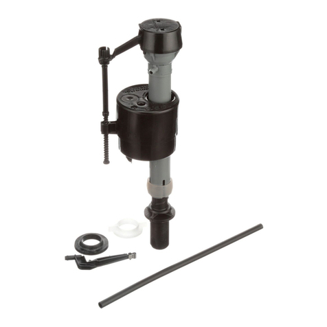
PIEZAS DEL ENSAMBLADO
+
O
SÓLO MIDA
LA ALTURA;
NO INSTALE
MARCA
“CL”
1"
NO MUEVA
EL ARO DE
SEGURIDAD
Abrazaderas de rodillo
y de manguera
4
2
0
6
8
Abrazaderas
de la manguera
PIEZA#4-753, Rev. 3, 02/09
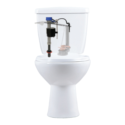
Si utiliza el
sistema de
limpieza Flush
’n Sparkle®, el
tanque debe verse
así al terminar
la instalación.
COMIENCE AQUÍ
Retire la válvula de llenado del tanque
Descargue el tanque y seque
con una esponja. Retire
la tuerca de acoplamiento
del suministro de agua y la con-
tratuerca de debajo del tanque.
Retire la válvula de llenado
del tanque.
Corte el suministro de agua.
(En dirección de las manecillas
del reloj)
1. 2. Prepare la válvula
para la instalación
Retire la arandela cónica
empujándola con el pulgar o
cortando con tijeras las cuatro
conexiones entre las arandelas
de espiga y cónicas. Deje a un
lado la arandela cónica.
IMPORTANTE: se recomienda utilizar un tapón de inodoro
con cadena de plástico o metal en el sistema Leak Sentry®
para conservar sus propiedades. Los tapones de inodoros
con correas de nailon o vinilo se estiran y hacen que
Leak Sentry®funcione incorrectamente.
(Reemplace el tapón por uno similar al Fluidmaster 501 ó 502.)
NO UTILICE
HERRAMIENTAS
NECESARIAS
continuación...
Retire el
ensamblado
de la tapa
de la válvula
2.
Coloque la
arandela de
espiga sobre la
espiga roscada
de la válvula
de llenado.
El lado plano
debe quedar
hacia arriba.
Luego coloque
la válvula de
llenado en el
tanque.
Coloque la válvula en el tanque,
no la instale. La marca de nivel
crítico (que se reconoce como
“CL” en la válvula de llenado)
debe estar al menos 2,54 cm
por encima de la parte superior
del tubo de desborde. Éste es
un código de plomería. Retire
la válvula de llenado del tanque
para ajustar la altura.
Ajuste la altura de la válvula
de llenado girando la espiga
roscada inferior hacia adentro
o hacia afuera del cuerpo de
la válvula. No mueva el aro
de seguridad, ya que éste
mantiene unidos bajo presión el
cuerpo de la válvula y la espiga.
No intercambie el cuerpo con
una espiga vieja, ya que pueden
producirse fugas.
Antes de instalar la
válvula, retire el ensamblado
de la tapa de la válvula.
Empuje el flotador hacia
arriba con la mano derecha
(consulte la imagen). Gire
la tapa y la palanca en
dirección contraria a las
manecillas del reloj 1/8 de
giro para desbloquear. Deje
el ensamblado de la tapa
colgando de la taza flotante.
ARANDELA
DE ESPIGA
ESPIGA
ROSCADA
Función para ahorrar agua: conexión de la cadena Leak Sentry®
4.
CONEXIÓN DE LA CADENA DE TAPÓN
DE INODORO
Levante la palanca del tanque hasta arriba dentro
del tanque. Sosténgala allí. Tire de la cadena de
tapón de inodoro dejándola tirante, de manera que
el tapón de inodoro quede abierto al máximo, y
conecte la cadena al orificio de la cadena que está
directamente sobre el tapón de inodoro. Asegúrese
de que la cadena de tapón de inodoro quede recta.
Asegúrese de que el tapón de inodoro se cierre
sobre su superficie de apoyo. De lo contrario,
puede que deba alargar en uno o dos eslabones la
cadena de tapón de inodoro para permitir que éste
se cierre y selle el tanque.
continuación...
3.
Lave los desechos: Sostenga una
taza sobre la válvula destapada
para que no salpique agua. Abra y
cierre completamente el suministro
de agua unas cuantas veces. Deje
el suministro de agua cerrado.
Verifique que no haya fugas. Apriete
las tuercas sólo lo suficiente para
evitar fugas.
Coloque el ensamblado de la tapa
sobre el cuerpo de la válvula gris
alineando el brazo de la tapa y la
varilla de ajuste con la manguera
de recarga.
Presione hacia abajo la tapa
superior girando la parte superior
y el brazo en dirección de las mane-
cillas del reloj a la posición
de bloqueo.
Abra el suministro de agua.
IMPORTANTE: sumerja la taza flotante
bajo el agua durante 30 segundos.
Ajuste el nivel del agua girando el
tornillo de ajuste del nivel de agua. Para
elevar el nivel de agua, gire el tornillo
en dirección de las manecillas del reloj;
para bajarlo, gire el tornillo en dirección
contraria a las manecillas del reloj.
Para su comodidad, la abrazadera del rodillo y la
abrazadera de manguera vienen preensambladas
a la manguera de recarga. Conecte un extremo de la
manguera al sujetador de recarga y deslice el sujeta-
dor a la derecha del tubo de desborde. Conecte el
otro extremo de la manguera al manguito roscado
de la válvula de llenado arqueando la manguera
un poco (consulte la imagen a la izquierda). Corte
el tubo si es necesario. Apriete las lengüetas de
la abrazadera de la manguera, llévela al extremo
de la manguera, sobre el manguito roscado de la
válvula de llenado, y suelte las lengüetas. No empuje
el tubo de recarga bajo el tubo de desborde. Esto
provocaría pérdida de agua.
CONEXIÓN DE LA CADENA
LEAK SENTRY®
Levante la palanca del tanque hasta arriba dentro
del tanque y sosténgala allí. Tire de la cadena Leak
Sentry®hasta que levante la taza flotante hasta el
tope de la espiga de la válvula de llenado. Luego
conecte la cadena y el sujetador a la palanca del
tanque, manteniendo la cadena tirante.
NOTA: no deje cruzadas las cadenas Leak Sentry®
y la del tapón de inodoro. Si la palanca tiene un
solo orificio, conéctelas al mismo orificio.
Pruebe la Leak Sentry®
5. Función para ahorrar agua: abrazadera del rodillo
6.
Revise el nivel del agua de la taza descargando el inodoro. Si la taza parece estar llena
pero sigue llenándose, es posible que la válvula esté saturando la taza y haciendo que el
exceso de agua se desvíe por el canal de sifón. Ajuste la cantidad de agua que ingresa a
la taza de la siguiente manera: llene la taza con 3,8 L de agua. Espere 3 minutos hasta
que el nivel del agua de la taza deje de descender. Con un lápiz, dibuje una línea en la
parte superior del nivel de agua de la taza. A continuación, descargue el inodoro. Si la
válvula sigue llenando la taza y el agua llega a la línea dibujada, la cantidad de agua que
ingresa a la taza es demasiada y debe ajustarse. Ajuste la recarga girando la abrazadera
del rodillo con el pulgar al siguiente número más bajo. Descargue el inodoro y ajuste
hasta que el nivel del agua de la taza quede en la marca dibujada cuando la válvula de
llenado se cierre. Si la válvula se cierra antes de que la taza se llene, ajuste girando la
abrazadera del rodillo al siguiente número superior. Repita este paso hasta que el agua
de la taza llegue a la línea. “O” en la abrazadera del rodillo significa que no hay descarga
SOLUCIÓN DE PROBLEMAS
LAVE LOS DESECHOS
30800 Rancho Viejo Road
San Juan Capistrano, CA 92675
www.uidmaster.com
800-631-2011
Retire el ensamblado
de la tapa
Lave la válvula
Vuelva a colocar el
ensamblado de la tapa
GARANTÍA
Este producto Fluidmaster
®
tiene una garantía
limitada durante un período de 5 años. Para
obtener detalles completos sobre la garantía,
visite nuestro sitio Web en www.fluidmaster.com
LA VÁLVULA DE LLENADO NO SE CIERRA.
IMPORTANTE: por las tuberías de agua pasa
arena y óxido. Siempre limpie los desechos
de las líneas de agua. Repita los pasos
“Retire el ensamblado de la tapa de la
válvula” y “Lave los desechos”.
LA VÁLVULA DE LLENADO NO SE ABRE.
• Si la taza flotante no baja cuando se
descarga el tanque: apriete la cadena
Leak Sentry®un eslabón e intente volver
a descargar. Apriete un eslabón a la vez
hasta que la válvula se abra al descargar.
Consulte “conexión de la cadena Leak
Sentry®”.
EL NIVEL DE AGUA EN LA TAZA ES
DEMASIADO BAJO.
• Mueva la abrazadera del rodillo a un
número superior.
LEAK SENTRY®NO BLOQUEA LA TAZA FLO-
TANTE.
• Asegúrese de que la válvula está ajustada
a las 5 en punto en el tanque.
• Asegúrese de que el agua descienda
por debajo de la taza flotante durante la
descarga. Levante más la válvula en el
tanque y vuelva a ajustar el nivel de agua.
• La cadena del dispositivo debe estar
holgada, excepto cuando se empuja
la palanca para descargar el tanque.
Consulte “conexión de la cadena Leak
Sentry®”.
• Desenrede la cadena de Leak Sentry®
del ajuste del tornillo o del área del
dispositivo.
PRECAUCIÓN: no empuje el tubo de recarga bajo el tubo
de desborde. Esto provocaría pérdida de agua del tanque.
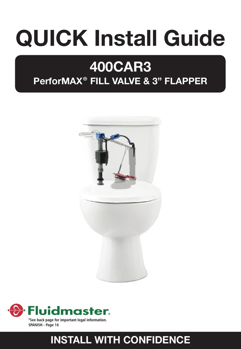
INSTRUCCIONES DE INSTALACIÓN
DE VÁLVULA DE LLENADO
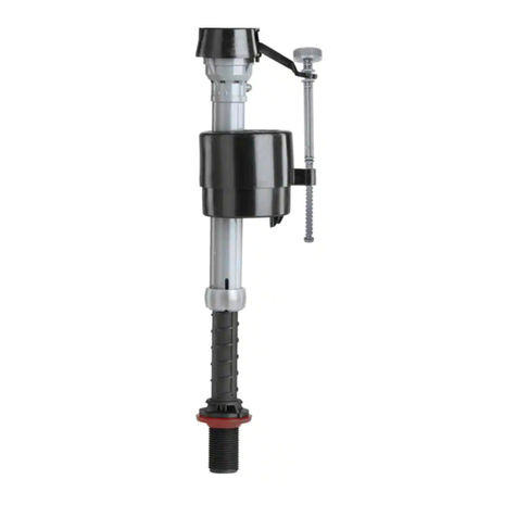
FLUIDMASTER®400LS CON
TECNOLOGÍA LEAK SENTRY®
NO UTILICE LIMPIADORES DE TAZA DE INODORO QUE SE COLOQUEN EN EL TANQUE O
SE SUMERJAN EN EL INODORO QUE CONTENGAN CLORO. El uso de este tipo de productos:
(1) PRODUCIRÁ DAÑOS en los componentes del tanque, POSIBLES INUNDACIONES, así como
DAÑOS A LA PROPIEDAD y (2) ANULARÁ LA GARANTÍA DE FLUIDMASTER. NO apriete
demasiado las tuercas o el tanque, ya que la taza se puede agrietar.
Se recomienda el sistema de limpieza de taza de inodoro Flush ’n Sparkle
®
de Fluidmaster para aquellos usuarios que
desean utilizar limpiadores de tazas dentro del tanque SIN ANULAR la GARANTÍA DE FLUIDMASTER, ya que este
sistema no daña los componentes.
FUNCIONES DE 400Ls PARA AHORRAR AGUA
Evita el desperdicio de recargas en tanques con filtraciones.
El dispositivo Leak Guard®advierte al usuario sobre las fugas en el tanque, generalmente
causadas por un tapón de inodoro defectuoso. Si hay una filtración en el tanque, la taza flotante no
bajará para rellenarlo hasta que se empuje la palanca del tanque. En el primer intento de descarga, la
válvula simplemente rellenará el tanque vacío y recién entonces usted podrá realizar una descarga
completa. Esto se repetirá hasta que se repare la filtración en el tanque. El sistema de recarga
ajustable le permite ajustar la cantidad de agua que ingresa a la taza, y elimina la pérdida de agua
que se produce cuando la taza está desbordada.
ADVERTENCIA
Dado que los limpiadores sumergibles usados dentro del tanque pueden
dañar las piezas de éste (consulte anteriormente GARANTÍA), Fluidmaster
recomienda el uso del sistema de limpieza de tazas de inodoro Flush ’n
Sparkle
®
(modelos 8100, 8200 ó 8300). Éste limpia el inodoro sin dañar
las piezas del tanque, aislando el limpiador del agua del tanque, y
liberándolo sólo a la taza cuando se necesita. Los cartuchos proporcionan
más de 1.000 descargas y se reemplazan rápidamente.
Instale la válvula
de llenado
3.
CONTRATUERCA
ARANDELA
CÓNICA
TUERCA DE
ACOPLAMIENTO
MECANISMO DE
CORTE DE AGUA
TUBERÍAS ABOCARDADAS
DE METAL/COBRE
CONTRATUERCA
ARANDELA
PLANA
TUERCA DE
ACOPLAMIENTO
MECANISMO DE
CORTE DE AGUA
TUBERÍA DE METAL
CON PESTAÑAS
CONTRATUERCA
ARANDELA
CÓNICA
EN ESPIRAL
TUERCA DE
ACOPLAMIENTO
MECANISMO DE
CORTE DE AGUA
TUBERÍA DE
METAL EN ESPIRAL
CONTRATUERCA
TUERCA DE
ACOPLAMIENTO
MECANISMO DE
CORTE DE AGUA
CONECTOR DE
VINILO/TRENZADO TUBERÍAS DE BOLA DE
COMPRESIÓN DE
PLÁSTICO O METAL
PRECAUCIÓN: el ajuste excesivo de la CONTRATUERCA o la TUERCA
DE ACOPLAMIENTO puede provocar roturas e inundaciones.
PRECAUCIÓN: NO utilice una ARANDELA CÓNICA en una LÍNEA
DE SUMINISTRO DE PLÁSTICO o un TUBO DE METAL EN ESPIRAL.
NO utilice masilla de plomero para sellar estos conectores. Estas piezas deben utilizarse como se muestra en la ilustración para garantizar conexiones herméticas.
Use la tuerca de acoplamiento Fluidmaster y
la arandela cónica para reemplazar las piezas
existentes. El tubo de suministro de agua
debe extenderse 1,3 cm dentro de la espiga
roscada de la válvula.
Use la tuerca de acoplamiento y
la arandela plana existentes. Use la arandela cónica en
espiral existente
No use la tuerca de acoplamiento ni
la arandela cónica de Fluidmaster en
tuberías de plástico o metal como
las que se muestran.
La arandela cónica cautiva viene incluida.
No se necesitan otras arandelas.
Utilice la tabla para determinar las piezas de ensamblaje adecuadas que se necesitan para reconectar correctamente el suministro de agua.
No utilice masilla de plomero para sellar estos conectores (la cinta de teflón es opcional).
Una vez colocadas las
arandelas correctas, ajuste
la tuerca de acoplamiento.
Apriétela sólo con las
manos. PRECAUCIÓN: no
utilice la arandela cónica
Fluidmaster en una línea de
suministro de plástico o un
tubo de metal en espiral.
Coloque la válvula
de llenado en el
tanque. Alinee el
manguito roscado
de la válvula de
llenado de manera
que quede recto
y paralelo a la
pared posterior del
tanque. Presione la
espiga hacia abajo,
a la vez que aprieta
la contratuerca.
Apriete sólo con
las manos.
Simule una fuga
levantando levemente
la cadena de tapón de
inodoro, y dejando salir
lentamente de 7 cm a 10
cm de agua del tanque.
La válvula de llenado
no debe abrirse, sino
permanecer cerrada.
Si la prueba falla,consulte
la sección de Solución de
problemas. Asegúrese de
que la cadena esté libre,
no enredada ni atascada.


