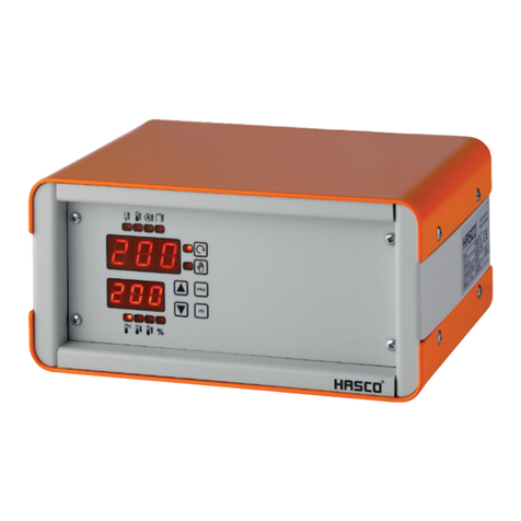
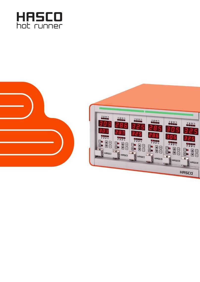
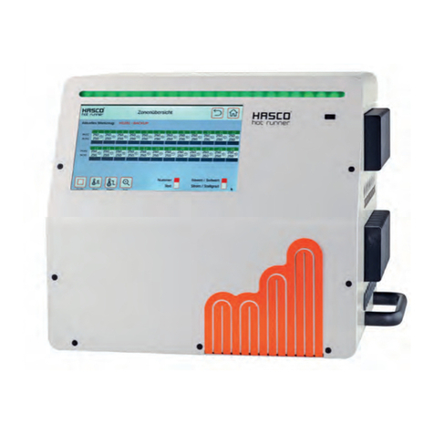
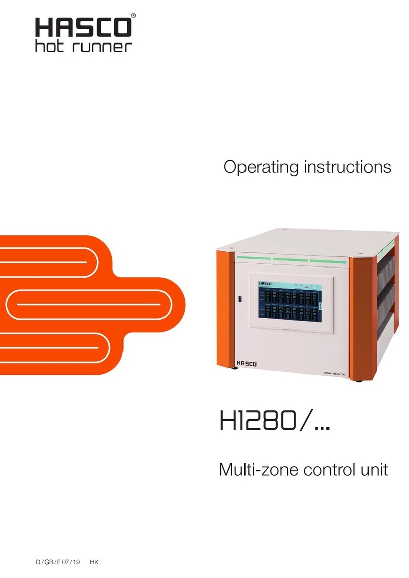
Hasco H1252 User manual

D 07 / 21 HK
Operating Instructions
H1252/...
Valuezone
Control unit


Instruction manual H1252
HASCO hot runner 3
Foreword
Thank you for choosing a HASCO hot runner product.
These operating instructions are intended for everyone who works with HASCO hot runner technology and explain
how to safely handle HASCO hot runner products.
These operating instructions must be read carefully by personnel whenever a product is brought into operation for the
first time. They must always be readily available during operation.
The operating instructions form the basis for the safe handling of HASCO hot runner technology. The instructions and
information given here, and particularly the safety rules, must be followed under all circumstances.
The general safety regulations and accident prevention regulations at the location in question must always also be
observed by personnel.
The operating instructions contain illustrations which serve for a better understanding only. In addition, the scope of
delivery for special versions or the latest technical changes can lead to deviations from the actual version supplied.
With this edition, all previous versions lose their validity.
Read carefully prior to use
and keep for future reference.

4 HASCO hot runner
Table of contents
List of Figures......................................................................................................................................5
1 Important information ............................................................................................................6
1.1 Symbols used 6
1.2 General safety information 6
1.3 Service address 6
2 Features and functionality......................................................................................................6
2.1 General information 7
2.2 Structure 7
2.2.1 H1252/6x16 8
2.2.2 H1252/12x16 9
2.3 Technology 10
2.3.1 Fuses 10
2.3.2 Mains voltage protection 10
2.3.3 Alarm contact/digital input 10
2.3.4 Pin assignment 11
2.4 Type plate 11
2.5 Electromagnetic compatibility 11
2.6 Technical data 12
3 Commissioning ...................................................................................................................13
3.1 Electrical connection 13
3.2 Operating and display elements 14
3.3 Quick start 17
4 Operation ...........................................................................................................................18
4.1 Zone selection 18
4.1.1 Selecting a single zone 18
4.1.2 Selecting several zones 18
4.1.3 Selecting several successive zones 19
4.1.4 Selecting all the zones 19
4.2 Mode of operation 20
4.3 Setpoint values 21
4.4 Output level 22
4.5 Parameters 23
4.5.1 Zone parameters 23
4.5.2 System parameters 24
4.6 Boost 25
4.7 Standby 26
5 Warnings and error messages .............................................................................................26
5.1 Warnings 27
5.2 Alarms 28
6 Functions and parameter setting..........................................................................................31
6.1 Basic settings 31
6.1.1 Access authorisations 31
6.1.2 Fahrenheit display 32
6.1.3 Thermocouple type 32
6.2 Control mode 32
6.2.1 Control parameter P I D 32
6.2.2 Rated value output level 33
6.2.3 Maximum output level 33
6.3 Heating 34
6.3.1 Gentle heating (soft start) 34
6.3.2 Combined heating 34
6.4 Hot runner monitoring 35
6.4.1 Temperature monitoring 35
6.4.2 Mean output level 37
6.4.3 Sensor fracture 37
6.4.4 Monitoring the heating current 38
6.4.5 Triac monitoring 38

Instruction manual H1252
HASCO hot runner 5
6.5 Special functions 39
6.5.1 Temperature increase BOOST 39
6.5.2 Temperature reduction STANDBY 39
6.5.3 Standard parameters 40
7 Parameter overview ............................................................................................................40
7.1 Zone parameters 40
7.2 System parameters 41
8 Spare parts + accessories ...................................................................................................42
9 Annex.................................................................................................................................43
9.1 Terminal diagram plug system 43
9.2 Clamping bridges for the star/triangle supply 43
9.2.1 Clamping bridges in the star network (state as delivered!) 43
9.2.2 Clamping bridges in the triangular network 43
List of Figures
Figure 1 - Housing front H1252/6x16 8
Figure 2 - Housing rear H1252/6x16 8
Figure 3 - Housing front H1252/12x16 9
Figure 4 - Housing rear H1252/12x16 9
Figure 5 - Side view H1252/12x16 10
Figure 6 - Operating and display elements 14
Figure 7 - Star network 45
Figure 8 - Triangular network 45

6 HASCO hot runner
1Important information
1.1 Symbols used
Caution! If this information is not heeded, disruptions or malfunctions can result.
Warning! If this warning is not heeded, damage to persons and/or damage to the machine can
result.
1.2 General safety information
For your safety, it is essential to observe the following information on the installation, commissioning and operation of the
controller:
- The controllers are operated on the low-voltage network. The relevant safety instructions must be observed when
connecting up and servicing the controller.
- The local and general regulations governing the installation and operation of the units must be complied with.
- The units may only be wired up and brought into operation by authorised specialists using the correct tools.
Specialist personnel in the terms of these Operating Instructions are persons who can recognise and assess the
dangers associated with the work entrusted to them on the basis of their specialist training, their experience and
their knowledge of the application of standards.
- To ensure reliable and safe operation, each user is obliged to observe the information and warnings.
- In the event of subcontracting, this documentation must be included and attention drawn to the need to observe
this safety information.
- The manufacturer and vendor of this unit are not liable for any direct or indirect damage due to its incorrect handling
or treatment.
The unit is checked carefully prior to delivery and has passed the tests specified in the test plan for production in conformity
with the manufacturer’s valid quality guidelines. To prevent any damage to the controller, it must be transported and stored
in the correct manner.
Further safety-related notices are marked in the individual sections of this documentation.
1.3 Service address
For technical enquiries and in case of complaint please contact us:
HASCO Austria GmbH
Industriestrasse 21
A-2353 Guntramsdorf
Austria
Phone +43 (0)2236-202-0
Fax +43 (0)2236-202-200
www.hasco.com

Instruction manual H1252
HASCO hot runner 7
2Features and functionality
2.1 General information
Hot runner controllers H1252/6x16 and H1252/12x16 are especially suited to the temperature control of hot runner moulds
on injection moulding machines. The controllers are linked directly to the mould via a cable connection.
During operation, hot runner controllers deliver electric current to the heating units on an injection mould. The so-called
heating current leads to an adjustable temperature increase in the heating units and hence in the mould. In parallel,
continuous temperature monitoring takes place via thermocouples that are connected up. In the event of deviations between
the current temperature recorded and the temperature set on the hot runner controller, the heating current is automatically
adjusted via a self-adapting PID control algorithm until the two temperatures are identical.
The controller variants of H1252/6x16 and H1252/12x16 differ solely in terms of the number of control circuits that are
possible. These are also referred to as heating zones. Depending on the variant, units are available with either 6 or 12 heating
zones.
2.2 Structure
Housing front: The hot runner controllers H1252/6x16 and H1252/12x16 are operated via the front of the housing (Figure
1). Alongside the three-pole main switch for switching the controller on and off, there are 12 buttons ensuring convenient
operation. The front of the unit also contains all the visualisation elements. The setpoint values and actual values of the
individual zones are portrayed via 7-segment displays. If required, the display can be switched to heating current and output
level. In addition, status LEDs provide information on operating modes and messages for the individual zones. The controller
status is visualised in colour via a fault-message display that is visible from a long way off. In normal operation, this display is
lit up green. In the event of a warning or an alarm, the display switches to yellow or red (traffic light status). This enables the
controller status to be readily assessed from a distance. A detailed description of the display and operating functions may
be found in Chapters 3.2 and 4.
Housing rear: All the connections and fuses of the hot runner controller are located on the rear of the housing (Figure 2). In
addition to the connection lead used to connect the controller to the mains electricity, the controllers have a further
connection for a potential-free alarm contact and a 24V digital input for external control of reduced-temperature (standby)
operation. The connection to the hot runner mould is achieved via 24-pole plug systems. The centrepiece of the hot runner
controller is the integral I/O board that is mounted on the rear of the controller housing. Each board contains the electronics
for 6 heating zones, the corresponding fuses and a cooling element. To ensure easy handling in the event of an error, all the
fuses for the I/O board are accessible on the rear of the housing.

8 HASCO hot runner
2.2.1 H1252/6x16
Figure 1 - Housing front H1252/6x16
Figure 2 - Housing rear H1252/6x1

Instruction manual H1252
HASCO hot runner 9
2.2.2 H1252/12x16
Figure 3 - Housing front H1252/12x16
Figure 4 - Housing rear H1252/12x16

10 HASCO hot runner
Figure 5 - Side view H1252/12x16
2.3 Technology
2.3.1 Fuses
The fuses for the load outputs and the control fuse are located on the rear of the controller housing. The specifications of the
fuses may be found in the technical data.
2.3.2 Mains voltage protection of sensor inputs
The hot runner controllers are equipped with mains voltage protection. This is designed to protect the sensitive electronics
in the sensor input zone against excessive high voltages. Voltages of this type can be caused by wiring errors or by
defective heating units, for example.
As soon as a voltage in excess of 6V is registered at the sensor inputs to the I/O board,
the zone in question is switched off via a relay.
The controller displays ‘sensor fracture’for this channel.
2.3.3 Alarm contact/digital input
The H1252 hot runner controllers have a potential-free alarm contact and a digital input that are fed out of the controller via
a socket on the rear.
The digital input is SPS-compatible, in other words it operates over a voltage range of 13..30 VDC with a typical current
consumption of approx. 8.5 mA. The potential-free alarm contact opens as soon as there is an error message. Chapter 5.2
contains a list of the possible error messages.
Alarm contact/digital input socket
Contact Function
1+3 Alarm contact Opener

Instruction manual H1252
HASCO hot runner 11
2 Digital input 0V reduced-
temperature (standby)
mode
6 Digital input 24V reduced-
temperature (standby)
mode
2.3.4 Pin assignment
The plug-in connections for the temperature sensors and heating elements are available on the rear of the controller.
These correspond to the terminal diagram in Annex 9.1.
2.4 Type plate
The type plate is on the right-hand side of the controller.
It contains the type designation with the number of zones, the electrical
connection data and the manufacturer’s data.
2.5 Electromagnetic compatibility
Emitted interference
The unit is interference-suppressed as per EN 55011/B (emitted interference).
Compatibility level:
VDE 0839 Part 10
Reliability class Z2
Environmental classes S2, I4, E3
Interference immunity:
VDE 0843 Part 2,3,4
IEC 801 Part 2,4,5
Environmental class 3
Severity 3, with external filter 4
H1252/ Year: XX/2017
Serial No. XXXXX
Mains supply: [ ] Y 230/400VAC [ ]50Hz
Max. 3x 32A [ ] ▲220VAC [ ]60Hz

12 HASCO hot runner
2.6 Technical data
HASCO Type H1252/6x16 Type H1252/12x16
Number of zones 6 12
Housing
Dimensions (WxHxD) 434 mm x 226 mm x 365 mm*1
Weight 13.5 kg 15.5 kg
Housing material Steel, galvanised
Protection IP 20
Ambient conditions
Service temperature 0...50°C
Max. housing surface temp.*2 55°C
Air humidity 0…90% rel. humidity, no condensation
Storage temperature -25...+75°C
Operation and display
Display per zone 2x three-digit 7-segment
Operating panel 12 buttons
Electrical connection
Connection cable with CEE plug 3 x 32 A
Supply voltage 3 x 190 –400 V AC, N, PE
Switchable to 3 x 110 –230 V AC, N, PE
Tolerance + 5% / -15%
Main switch 40 A 3-pole
Mains electricity fuses
Control voltage electronics 1 x 4A medium time-lag (6.3 x 32mm)
Heating outputs external each 16A gRL (6.3 x 32mm)
Additional fuses internal each 16A time-lag (6.3 x 32mm)
Power consumption Max. 30 W when idling
Thermocouple inputs
Thermocouple Fe-CuNi Type J - 0…700°C
switchable to NiCr-Ni Type K
Cold junction compensation internal
Measuring accuracy ±0.25 K
Temperature polling 4x128 / second

Instruction manual H1252
HASCO hot runner 13
Load outputs Bistable, electrically isolated
Per zone 1x heating, 230VAC switching
Shortest controller reaction 10ms at 50Hz
Current per zone max. 16A at 80% operating time
Important warning! Observe the overall capacity of the electrical connection lead
Minimum load 100 W
Control mode PI, PD or PID set separately for all zones
Other connections
Alarm output (relay contact) - potential-free
Maximum voltage 250V AC
Maximum current 4A at cosj= 1; 2A at cosj= 0.5
Digital input –isol. potential-free 13 –30V DC
1 Depth dimension without mould connection
*2: for an air temperature of 20°C
3Commissioning
3.1 Electrical connection
The electrical connections must be performed by a trained electrician. Commissioning and
operation while the controller is running are only to be carried out by authorised qualified
personnel.
Switching off all the outputs or individual zones will not protect any of the outputs against
hazardous voltages. Before working on the connected heating elements, the associated
connections must be unplugged, or the entire unit disconnected from the mains power. Before
the unit is opened, it must be disconnected from the mains power.
Mains electricity
Before connecting the unit to the mains voltage, a check must be conducted to see that the mains electricity system is
correct. The hot runner controllers H1252/6x16 and H1252/12x16 are prepared by default for operation in a star network
(3x400VAC + N + PE), but can also be operated in a triangular network (3x230VAC + PE). For operation in a triangular
network without a neutral conductor, it is essential to observe the local regulations for the installation of electrical systems.
The terminals in the controller must be bridged accordingly for use in a star or triangular network. Annex 9.2 contains a clear
terminal connection diagram.
Connection to the mains electricity:
To ensure correct operation, the hot-runner controller is connected to the low-voltage mains by means of the connection
lead attached to the unit.
Connection of the mould:
To connect the individual control zones to the corresponding injection mould, use must be made of appropriate leads for the
sensor and heating unit connection.
Figure 2 - Housing rear H1252/6x16 shows the plug system for connecting the H1252/6x16 controller to the mould by way
of example.

14 HASCO hot runner
3.2 Operating and display elements
The following diagram shows the front view of the controller, with all the operating
and display elements.
Figure 6 - Operating and display elements
Operating/display element Description
Fault-message display
Green shows that everything is in order.
The controller is operating normally.
Yellow indicates warning messages about a
deviation from the normal state.
Red indicates alarms. Depending on the fault,
the outputs of the corresponding zones may be
deactivated.

Instruction manual H1252
HASCO hot runner 15
Zone selection
Each time the arrow buttons are pressed, the
display moves on to the next zone.
Value change with confirmation button
Confirmation button/acknowledge fault
Boost
Standby
Change operating mode
Set parameters/system information
Hand-operated (yellow)
Flashing = operated by hand due to incident
Regular operation (green)
Alarm warning (red)
Flashing = alarm
Displays the last selected zone

16 HASCO hot runner
Basic view: display of all zones/ cancel entry
Button for switching the zone display
Display: actual value (X) and setpoint value
(W)
Display: current (I) and output level (Y)
Activate/deactivate controller
outputs
Temperature unit used for display
Main switch for switching on the controller.

Instruction manual H1252
HASCO hot runner 17
3.3 Quick start
1. Connect up the heating and sensor lines. The plug system assignment is set out in Annex 9.1.
2. Connect up to the mains as per Chapter 3.1
3. Switch on the controller at the main switch
4. Select the control zones required (Chapter 4.1)
5. Switch the operating mode of the required zones from “off”(control zone switched off) to “on”(normal control
mode) (Chapter 4.2)
6. Set the individual setpoint values for the required control zones (Chapter 4.3)
7. Activate the controller outputs
The alarm limits for an excessively high temperature (parameter ) and the upper temperature limit
(parameter ) should be aligned to the production conditions to prevent incorrect heating.
After the controller outputs have been activated, the control parameters will automatically be aligned to the control loop.
Following this, the system will move towards the specified setpoint values, with the relevant functions such as soft start and
combined heating being active. These functions can also be deactivated as per Chapter 6.3.

18 HASCO hot runner
4Operation
4.1 Zone selection
4.1.1 Selecting a single zone
Step Operation Description
1.
Each time the arrow buttons are pressed, the display
moves to the next zone.
All other zones that have not been selected are blanked
out.
4.1.2 Selecting several zones
Step Operation Description
1.
Select zone
2.
Confirm the zone.
…repeat 1 and 2 in order to select any desired zones

Instruction manual H1252
HASCO hot runner 19
4.1.3 Selecting several successive zones
Step Operation Description
1.
Choose the 1st zone that is to be selected.
2.
Keep the confirmation button pressed.
3.
Each time the button is pressed a zone is added to the
zones selected.
4.
Release the confirmation button
4.1.4 Selecting all the zones
Step Operation Description
1.
The following fundamentally applies:
In the basic view, all the zones can be operated and are
thus already selected for a value change, as it were.
“The zones that you can see, you can also operate.”

20 HASCO hot runner
4.2 Mode of operation
Step Operation Description
1.
Select zones as described under 4.1
2.
Select the operating mode
Each time the button is pressed the display changes
between
Manual operation
Normal operation
Zone off
Note: the display flashes and must be confirmed within 5
seconds.
3.
Confirmation of the entry made.
The display no longer flashes.
4.
Press the home button to return to the
display of all the zones.
Table of contents
Other Hasco Control Unit manuals
Popular Control Unit manuals by other brands
Quintex
Quintex Cheetah C3 CUB operating & maintenance manual
Millenium
Millenium HD-120 user manual
Beta LaserMike
Beta LaserMike LASERSPEED 8000 Instruction handbook
National Instruments
National Instruments NI-9244 User manual and specifications
Texas Instruments
Texas Instruments Piccolo F280049C user guide
WAGO
WAGO WAGO-I/O-SYSTEM 750 Series manual
