Fluidmaster THE EVERYTHING K-400H-038 User manual

K-400H-038
‘THE EVERYTHING’TM
3˝ TOILET TANK REPAIR KIT
HOW-TO VIDEO
VISIT: FLUIDMASTER.COM
K-400H-038 PRODUCT PAGE
VIDEO
HELPFUL
TOOLS INCLUDED!
SPANISH - Page 23
*See back page for important product warnings and warranty information.
2 3
STEP 1: PREPARE TANK
GETTING STARTED
SEE INSTRUCTION VIDEO ON WEBSITE FOR REFERENCE.
B: DRAIN WATER
Flush toilet to drain most of the water from tank.
FLUSH
A: TURN OFF WATER
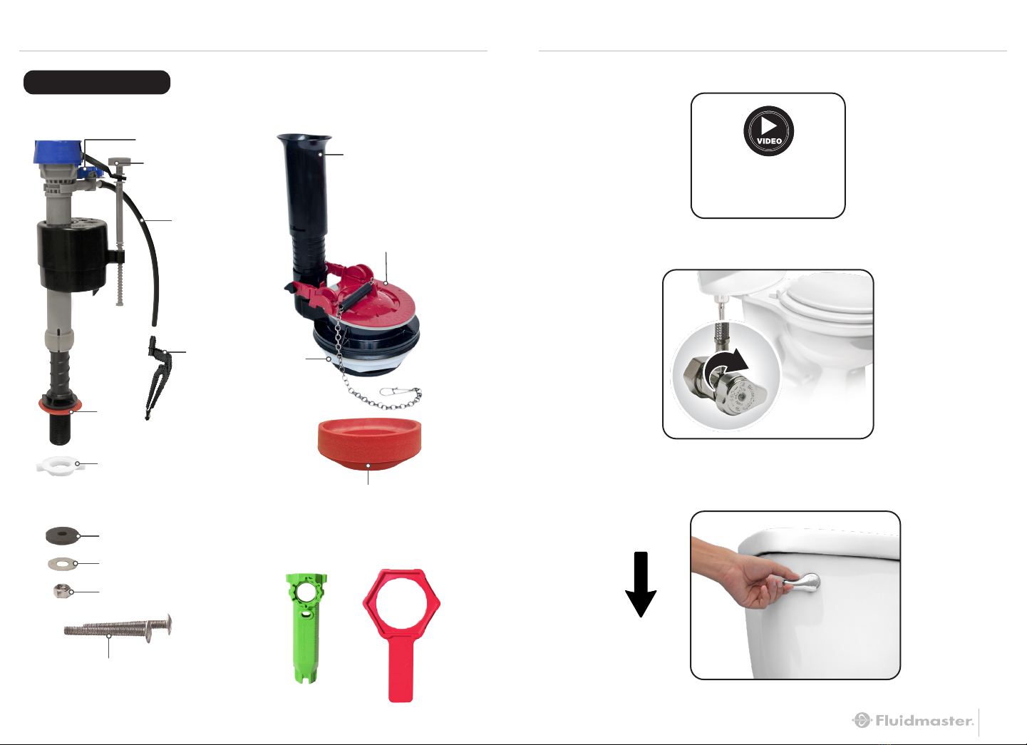
PARTS OVERVIEW
PERFORMAX®FILL VALVE FLUSH VALVE
TOOLS
Rubber Washer (x2)
Stainless Steel Washer (x2)
Large Hex Nut (x2)
Stainless Steel Bolts (x2)
Locknut
Shank
Washer
Refill Tube
Tank Water Level
Adjustment Screw
Bowl Water Level Dial
Refill Clip
Red WrenchGreen Tool
HOW-TO VIDEO
VISIT: FLUIDMASTER.COM
K-400H-038 PRODUCT PAGE
Red Tank-to-Bowl Gasket
Overflow Pipe
3” Universal Flapper
Locknut

4
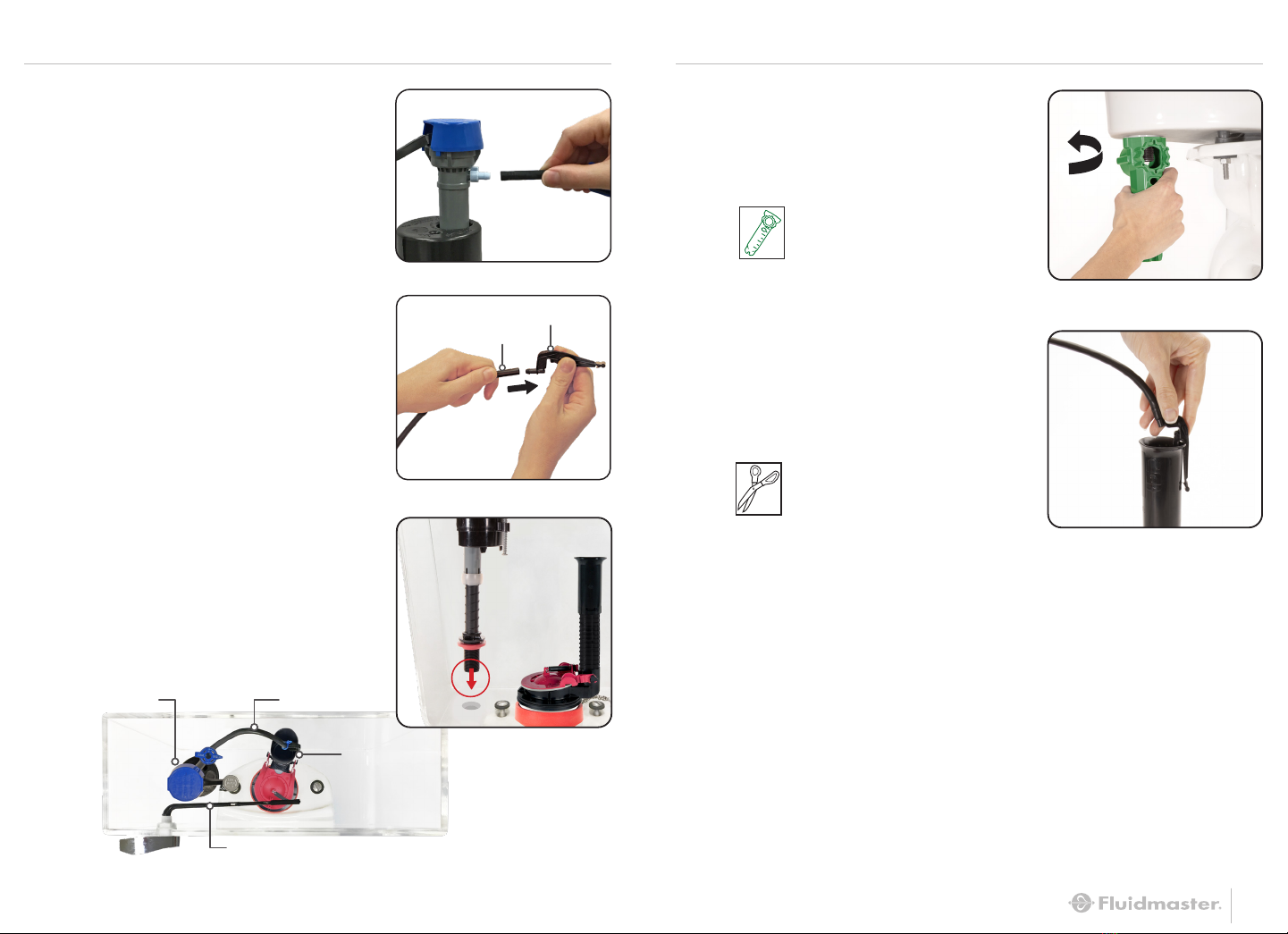
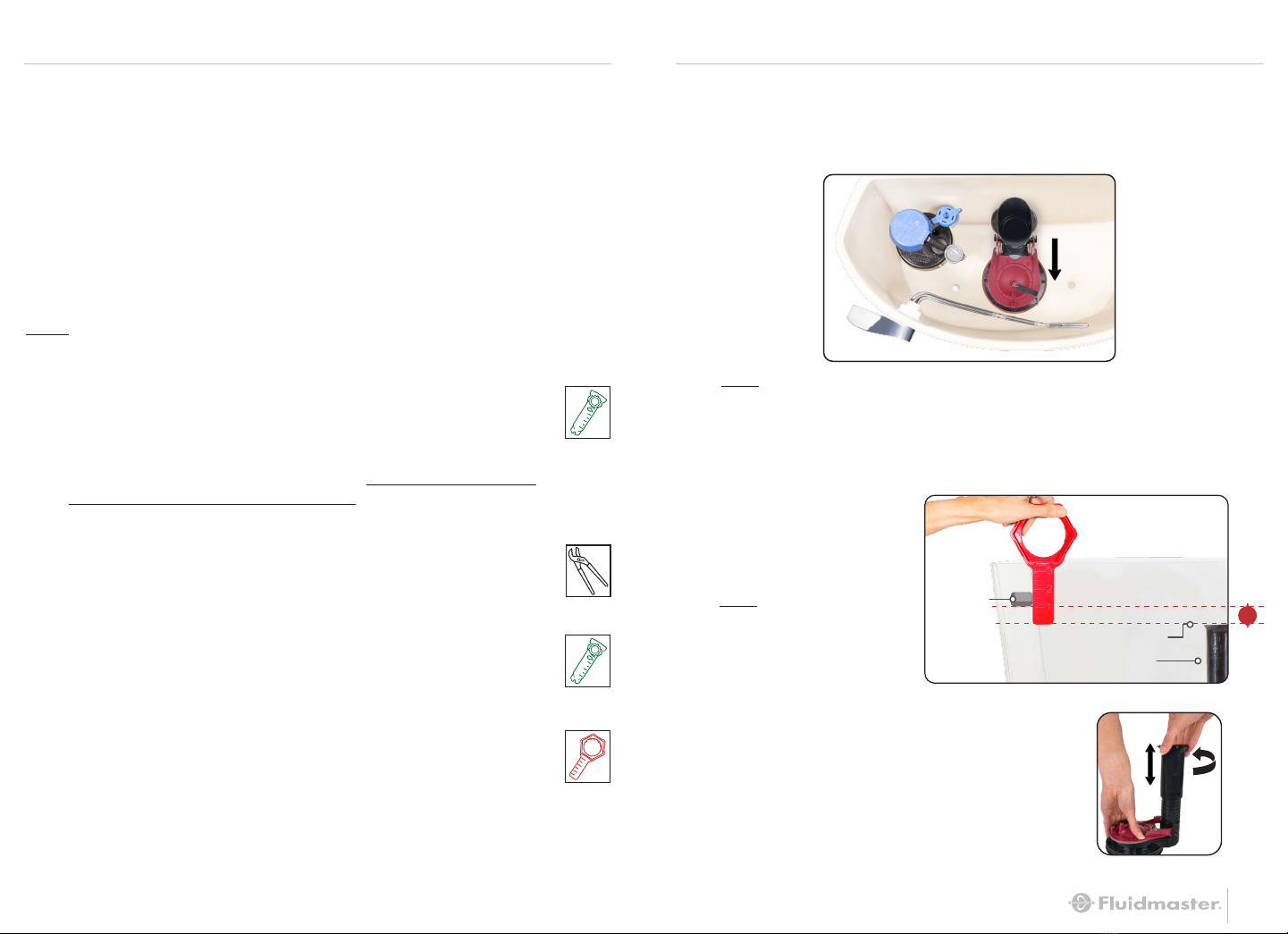
STEP 2: REMOVE OLD PARTS
A: REMOVE CONNECTOR
Remove water supply
connector from bottom of fill valve.
E: REMOVE TANK FROM BOWL
Use green tool to unscrew nuts from
under the bowl and remove bolts
from tank.
G: REMOVE GASKET
Remove tank-to-bowl gasket from
below the tank.
F: LAY TANK ON ITS SIDE
Place on a safe and secure surface.
H: REMOVE FLUSH VALVE
LOCKNUT
Using red wrench, twist locknut
to remove. Remove old flush valve
from tank.
B: REMOVE OLD LOCKNUT
Use green tool to twist locknut below
tank to remove locknut from fill valve.
C: REMOVE OLD FILL VALVE
Including refill tube, refill clip and
shank washer. Drain any excess
water into the back panel of
empty packaging by removing fill
valve from tank. (Pull fill valve up)
D: DISCONNECT
FLAPPER CHAIN
Towel
(Optional)
NOTE: Inspect water
supply connector. Replace it if
it is worn, or you don’t know
how old it is, to prevent flooding
and property damage.
5
Screwdriver
(Optional)
Red Wrench
Green Tool
Green Tool
NOTE: Bolts can be
loosened from inside tank.
Tank Lever

6 7
STEP 3: INSTALL FLUSH VALVE STEP 3: INSTALL FLUSH VALVE (CONTINUED)
B: USE RULER ON THE RED WRENCH TO MEASURE
AND ADJUST NEW FLUSH VALVE
Mark the flush valve 1” below bottom of tank lever hole.
NOTE: Do not cover tank bolt holes with flush valve. If flush valve covers
a bolt hole, turn flush valve slightly to the right (overflow tube to the right)
to clear the bolt hole. In some cases, placing bolts in the holes first may
be necessary.
A: INSERT FLUSH VALVE INTO TANK HOLE
Position overflow pipe toward back of tank.
NOTE: The top of the overflow pipe must be at minimum of 1” below
the tank lever hole.
TOP OF
OVERFLOW PIPE
Overflow
Pipe
Lever Hole
1"
BOTTOM OF
TANK LEVER HOLE
Adjusted
Height
C: ADJUST FLUSH VALVE HEIGHT
Twist to unlock, pull or push to correct
height, twist to lock in place.

8 9
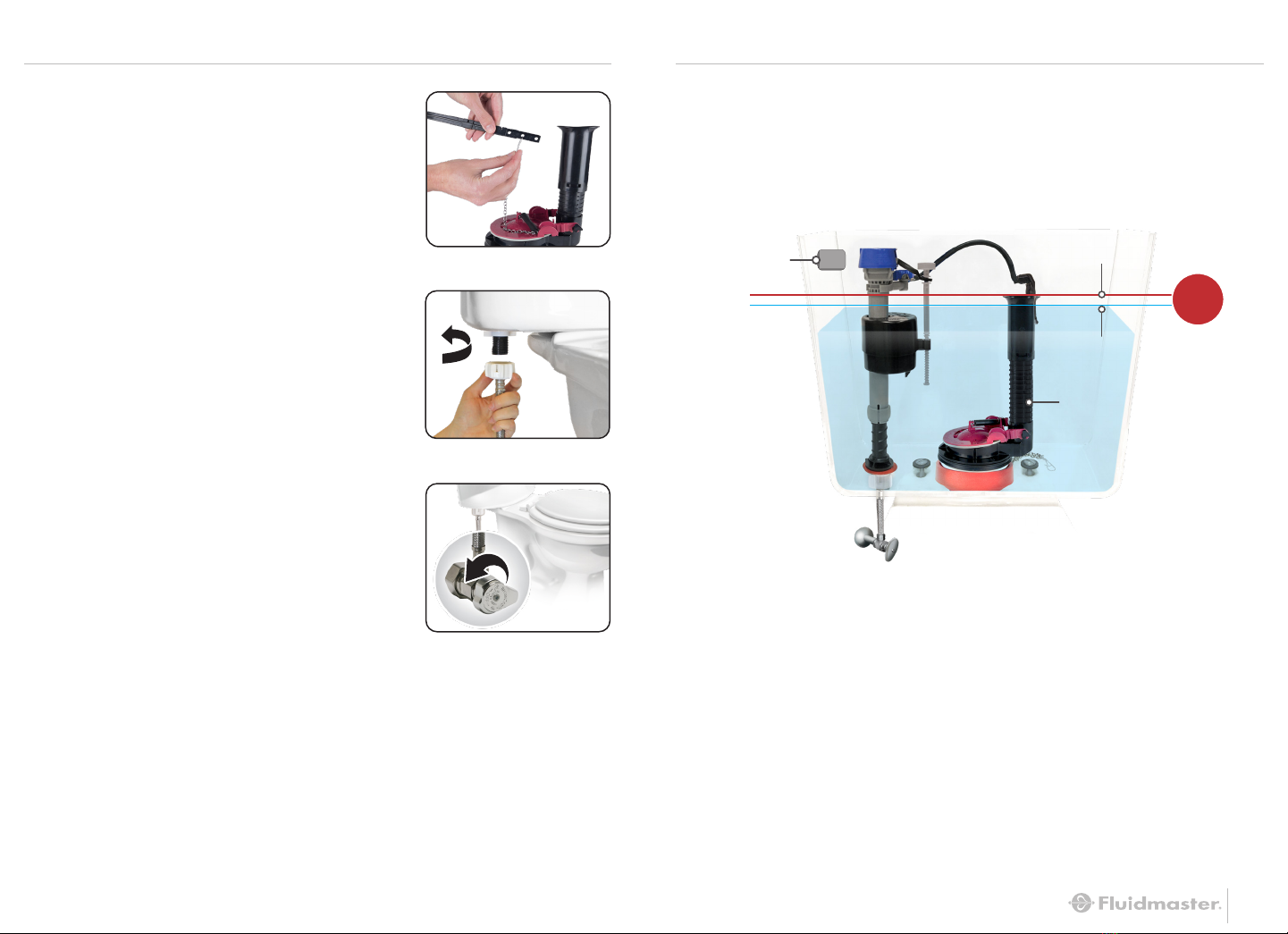
STEP 4: INSTALL TANK-TO-BOWL GASKET STEP 5: SECURE TANK TO BOWL
B: Apply red tank-to-bowl gasket to
bottom of flush valve locknut, fully
covering locknut.
Red Wrench
A: INSTALL LOCKNUT
Holding flush valve in place, screw locknut onto bottom of
flush valve and hand-tighten to secure. Use red wrench to
go ½ turn beyond hand-tight.
Do not overtighten.
A: INSTALL RUBBER WASHERS
Place one rubber washer on each
tank bolt.
B: INSERT BOLTS INTO TANK
Place tank bolts through bottom
holes of tank.
C: SECURE TANK ONTO BOWL
Set tank onto bowl. Place metal
washer and large hex nut on each
bolt under toilet bowl. Using green
tool, tighten hex nuts evenly until
tank is snug and does not rock. Do
not overtighten.
Rubber
washer
Rubber
washer
Tank
Metal washer
Large hex nut
Bowl
Green Tool

10 11
STEP 7: ADJUST HEIGHT OF NEW FILL VALVE
A: TWIST FILL VALVE TO ADJUST HEIGHT
Top of fill valve cap should measure roughly 3”
above top of overflow pipe when installed.
TWIST
LEFT
NOTE:
Increasing height allows
more water to fill in the tank.
HOLD
Do Not Move Lock Ring
**The top of the overflow pipe must be a minimum of 1" below tank lever hole.
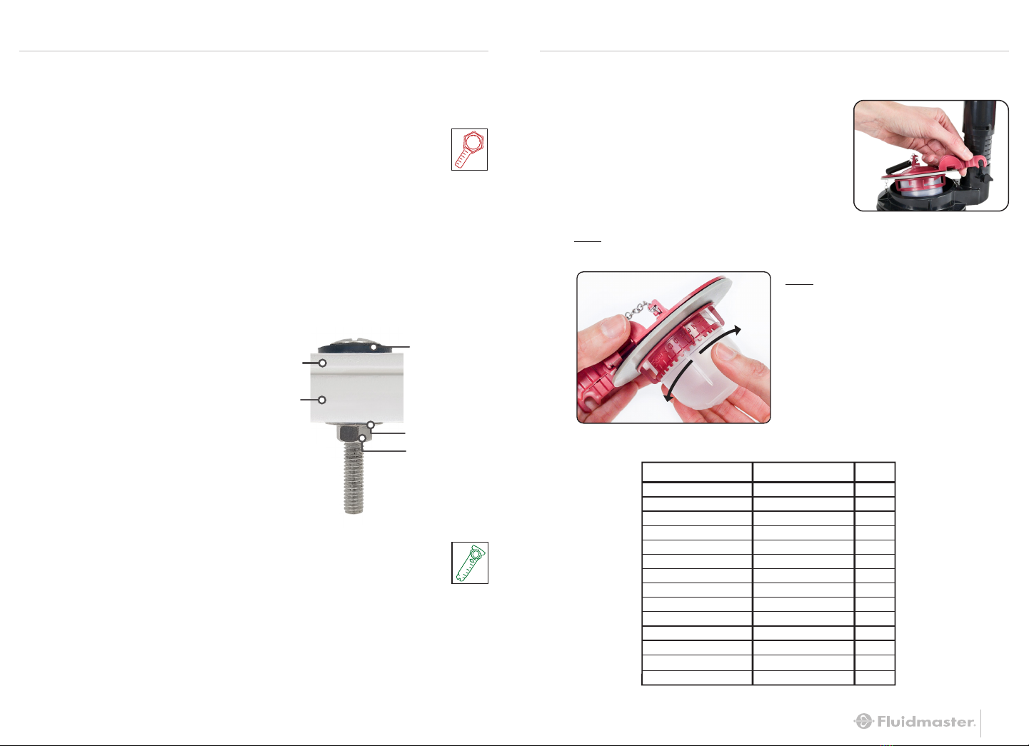
STEP 6: ADJUST FLAPPER
A: REMOVE FLAPPER
Remove flapper from flush valve by
pulling the frame of the flapper up one
side at a time.
B: ADJUST FOR MOST EFFICIENT FLUSHAdjust from
0 to 10 to find the perfect flush for your setup.
Hint: The higher the number,
the longer the flapper stays
open for more water flushed.
FLAPPER SETTINGS
AMERICAN STANDARD
CATO
ELJER
GERBER
GLACIER BAY
KOHLER
MANSFIELD
ST. THOMAS
PEGASUS
TOTO
VITRA
Cadet 3
Titan
Avalanche
2-Pc High Efficiency
Cimarron
Maverick
Arlington
Palermo
Westminster
Drake
Clayton
Vespin
Corina
8
8
0
6
3
1
5
0
6
9
6
0
6
5
SETTINGBRAND MODEL
Note: Flapper dial is pre-set to maximum setting (10). If toilet model
not listed, keep flapper at
default setting 10.
Fill Valve Cap
Overflow Pipe
*Lever Hole
TOP OF FILL VALVE CAP
TOP OF
OVERFLOW PIPE
3"
D: INSTALL LOCKNUT
Using green tool, screw locknut
onto fill valve shank (below tank).
Tighten 1/4” beyond hand-tight.
Do Not Overtighten*.
E: ATTACH REFILL CLIP TO
OVERFLOW PIPE
Note: If refill tube is too long to fit
inside tank with lid closed, remove
refill tube from fill valve refill port, cut
tube and reattach to port.
Scissors
(Optional)
12
STEP 8: INSTALL NEW FILL VALVE STEP 8: INSTALL NEW FILL VALVE (CONTINUED)
13
A: PUSH REFILL TUBE
ONTO REFILL PORT
B: ATTACH REFILL CLIP
TO OTHER END OF
REFILL TUBE
*Overtightening may crack the fill valve or tank causing flooding. Make sure the float cup
does not touch the tank walls or tank lever and flush valve.
Refill Clip
Refill Tube
C: INSERT FILL VALVE
Position refill tube to face flush
valve making sure fill valve parts
do not interfere with lever arm.
TOP
DOWN
VIEW
Refill Tube
Lever Arm
Overflow
Pipe
Fill Valve
Green Tool
14 15
STEP 9: FINISHING STEPS STEP 9: FINISHING STEPS (CONTINUED)
B: ATTACH WATER SUPPLY
CONNECTOR TO FILL VALVE
*Hand-tighten only. Do not overtighten.
D: WATER LEVEL
After the tank stops filling, water level should fill the tank to
roughly ½” below top of overflow pipe to ensure a proper flush.
(Does not need to be exact.)
C: TURN ON WATER
Check for leaks.
1/2"
Overflow Pipe
Top of
Overflow Tube
Water Level
Lever Hole
* Overtightening may damage fill valve or coupling nut, potentially causing flooding.
Make sure the float cup does not touch the tank walls or tank lever and flush valve.
**The top of the overflow pipe must be a minimum of 1" below tank lever hole.
A: CONNECT FLAPPER CHAIN
Attach clip to the tank lever directly
above the flapper. Leave roughly ½”
of slack (small ‘J’ shape) in the chain.
16 17
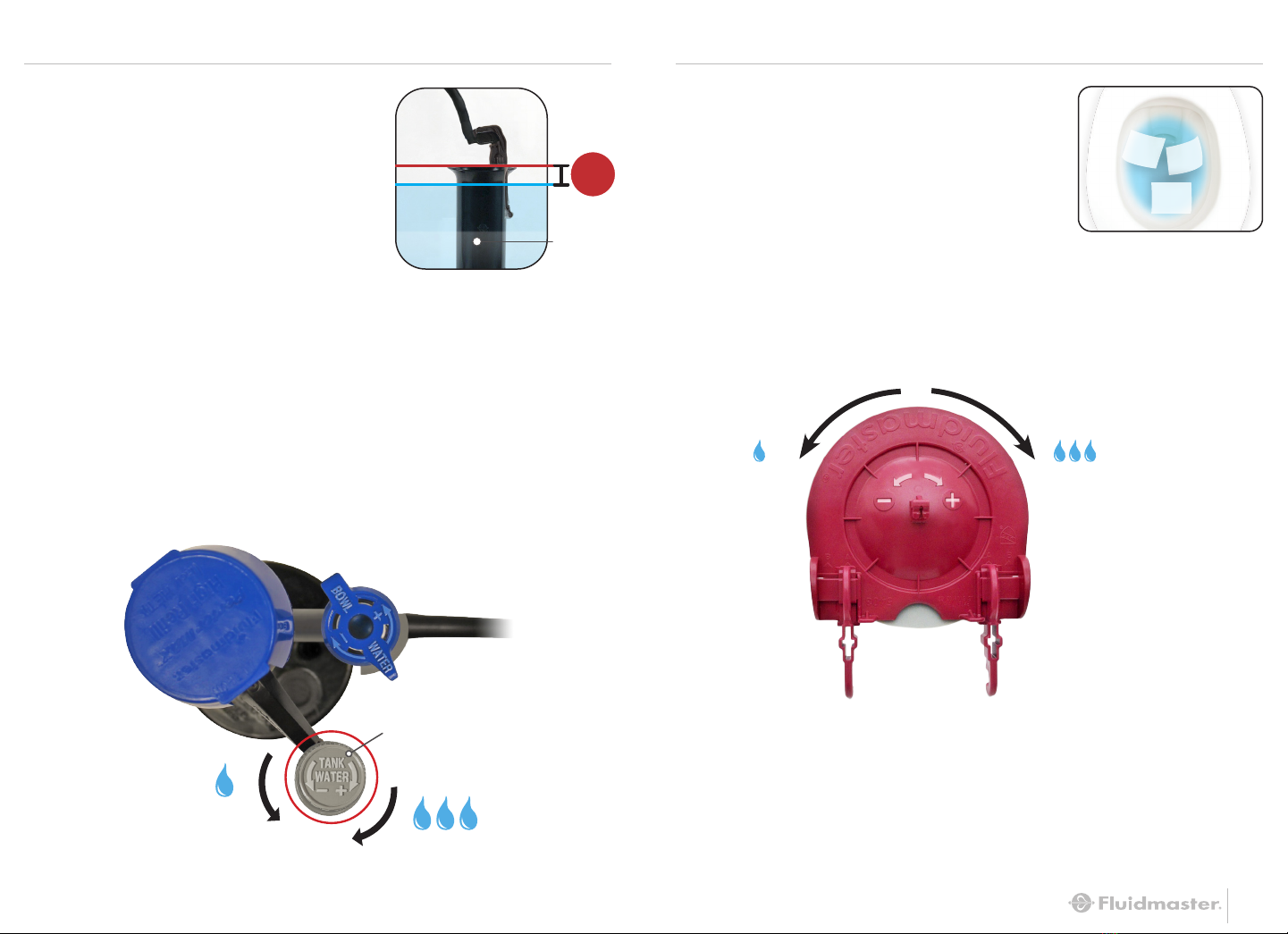
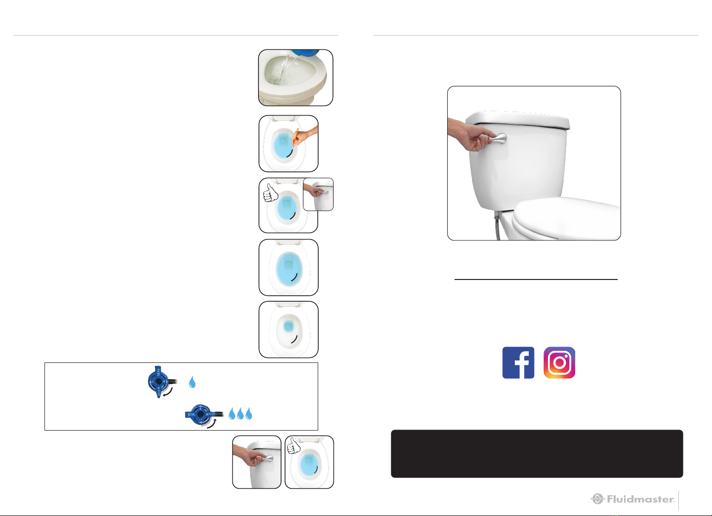
STEP 10: FINE-TUNE TANK WATER LEVEL STEP 11: FINE-TUNE FLUSH
A: FLUSH THE TOILET TO
CHECK THE TANK WATER
LEVEL
After the water stops filling the
tank, the water level should be
roughly ½ inch below the top
of overflow pipe to ensure a
proper flush.
A: TEST FLUSH
Drop 3 squares of toilet paper in
bowl then flush.
B: WATER LEVEL IS TOO LOW
Turn the tank water level adjustment screw clockwise to
raise the float. Flush to reset water level.
WATER LEVEL IS TOO HIGH
Turn the water level adjustment screw counterclockwise to
lower the float. Flush to reset water level.
1/2"
Overflow
Pipe
See Step 7A for Full Tank view.
Tank Water Level
Adjustment Screw
+
–
MORE
WATER
FLUSHED
LESS
WATER
FLUSHED
B: ADJUST FOR MOST EFFICIENT FLUSH
Continue to adjust dial down one setting and flush until toilet
is unable to flush paper properly.
C: FINAL SETTING
Once unable to flush, adjust dial up one for final setting.
Hint: The higher the number,
the longer the flapper stays
open for more water flushed.
Note: Turn off water. Remove flapper for easy adjustment (see Step 6).
18 19
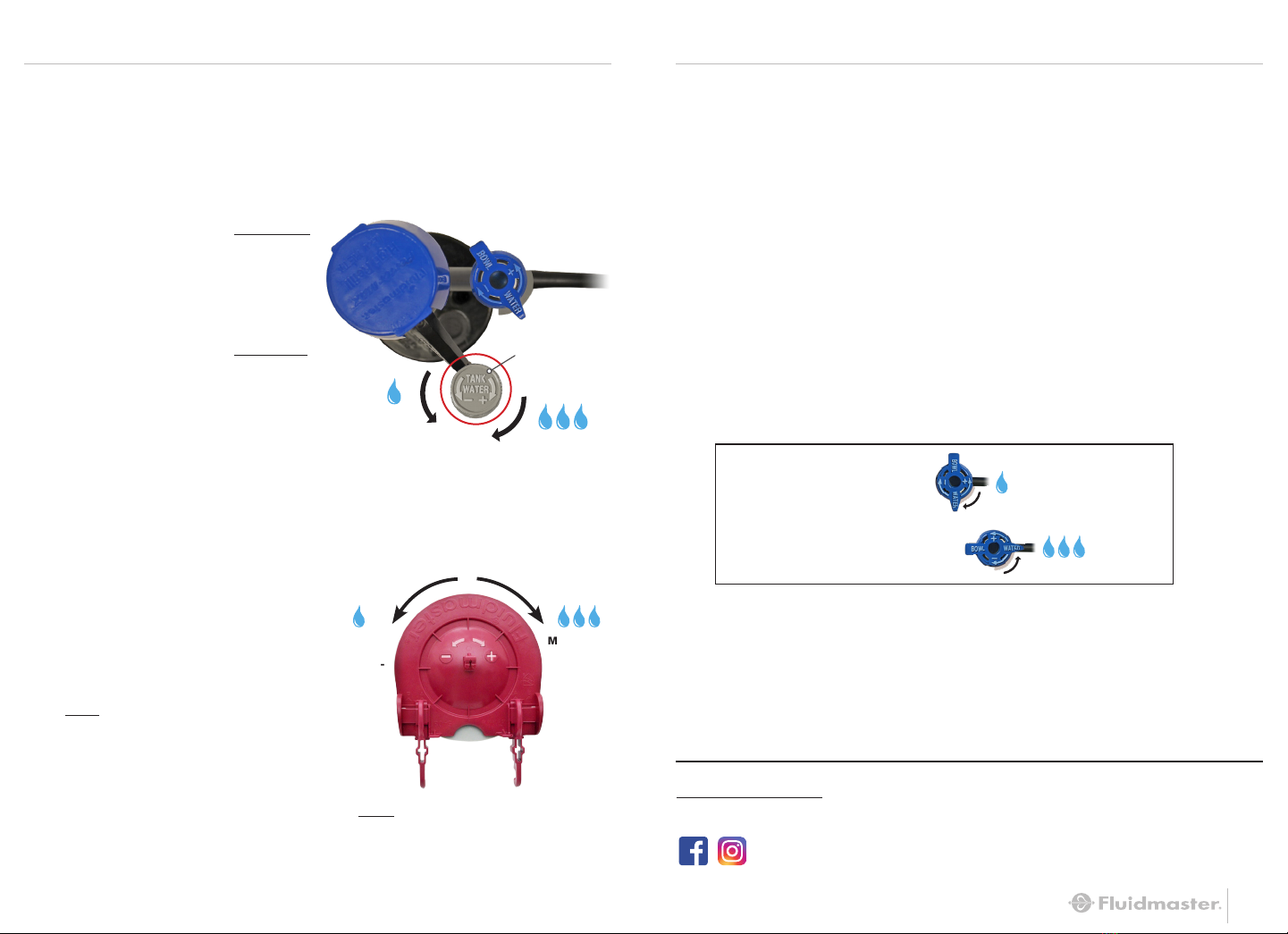
STEP 12: FINE-TUNE BOWL WATER LEVEL
A: FILL BOWL WITH A GALLON OF WATER
Wait 1 minute until the bowl water level recedes
down and stops.
B: MARK THE WATER LEVEL IN THE BOWL
With a pencil, draw a line at the top of the water level
in bowl. (Pencil mark will easily wash off).
C: FLUSH TOILET TO CHECK BOWL
WATER LEVEL
If the water level matches the line you’ve made in
the bowl when the fill valve stops filling the tank,
the water level is correct, proceed to Step 13.
TOO HIGH
TOO LOW
If the water level matches the line in the bowl and the
fill valve is STILL FILLING, then the bowl water is
TOO HIGH, proceed to Step 12D.
If the valve shuts off and the water level does NOT
match the line in the bowl, the water level is TOO
LOW, proceed to Step 12D.
E: FLUSH TOILET,
CHECK BOWL WATER LEVEL
Repeat Steps 12D and 12E until water level in bowl
matches the line when the fill valve shuts off.
D: ADJUST THE BOWL WATER LEVEL
TOO HIGH:
Turn the dial clockwise.
TOO LOW:
Turn the dial counter-clockwise.
Still not working exactly right?
See the next page for Troubleshooting.
YOU DID IT!
We knew you could!
Share your success story
with friends and family!
#FixedMyToilet
#Fluidmaster
STEP 13: FLUSH THE TOILET
A: FLUSH THE TOILET
If you’re satisfied with the flush, YOU’RE DONE!
LESS WATER
MORE WATER

20 21
A: WATER FROM REFILL TUBE MUST
FLOW THROUGH OVERFLOW PIPE
Make sure the refill tube is supplying water down
overflow pipe. (Metal side out for refill clip)
A: ADJUST THE FLAPPER SETTING TO A LOWER NUMBER
(See page17, step 11B.)
B: WATER LEVEL IN TANK MAY BE TOO LOW
1/2” below top of overflow pipe is recommended
(see page 15).
C: FLAPPER MAY BE CLOSING TOO SOON
Give flapper chain approximately 1/2" of slack
(small “j” shape).
WATER LEVEL IN BOWL IS TOO LOW
MY FLAPPER STAYS OPEN TOO LONG & I GET A DOUBLE-FLUSH
REPLACE FILL VALVE SEAL
• Place cap assembly on top of gray valve body by
aligning cap arm and adjustment rod next to refill tube.
• Press down on top cap while rotating top & arm clockwise to locked position.
A: Remove cap (see above).
B: Replace seal with a *genuine Fluidmaster
242 Seal.
C: Replace valve cap.
*Always use genuine Fluidmaster parts when installing or repairing. Fluidmaster will not be
responsible or liable for use of non-Fluidmaster parts during installation or repair.
TROUBLESHOOTING
IF THE FILL VALVE: • DOES NOT TURN ON
• WON’T TURN OFF
• WON’T REFILL TANK
REMOVE CAP AND CHECK FOR DEBRIS
A: Turn off water supply, then flush toilet.
B: With right hand push float up, grip and
hold shaft under float.
C: With left hand twist cap and lever arm
counterclockwise to unlock cap. Let cap
hang on float cup.
D: Hold empty cup upside down over un-
capped valve to prevent splashing.
E: Turn water supply on and off a few times,
then leave it turned off.
F: Replace valve cap.
• Place cap assembly on top of gray valve
body by aligning cap arm and adjustment
rod next to refill tube.
• Press down on top cap while rotating top &
arm clockwise to locked position.
See Our Troubleshooting HOW-TO VIDEO
http://bit.ly/2yAdZn7
VIDEO
D: FILL VALVE DIAL MAY NEED TO BE
ADJUSTED (see page 18).
Seal
Cap
Overflow
Pipe
Refill Tube
1/2"
Overflow
Pipe

23
NOTES GUÍA DE INSTALACIÓN RÁPIDA
RESUMEN DE PIEZAS
VÁLVULA DE LLENADO PERFORMAX®VÁLVULA DE DESCARGA
HERRAMIENTAS
Arandela de Goma (x2)
Arandela de Acero Inoxidable (x2)
Tuerca Hexagonal Grande (x2)
Pernos de Acero Inoxidable (x2)
Contratuerca
Junta de
Vástago
Manguera de
Relleno
Tornillo de Ajuste
del Nivel de Agua
del Tanque
Abrazadera de la
Manguera de Relleno
Clip de
Relleno
Llave RojaHerramienta
Verde
Empaquetadura de
Taza-a-Tanque
22
Contratuerca
Tapón
Universal de 3”
Tubo de Desagüe
24 25
PASO 1: PREPARE EL TANQUE (IMÁGENES: P.3)
A: CIERRE EL AGUA.
B: DRENE EL AGUA. Descarge el inodoro para drenar la mayor parte del agua
del tanque.
A: REMUEVA EL CONECTOR. Remueva el conector de suministro del agua
de la parte inferior de la válvula.
NOTA: Inspeccione el conector de suministro de agua. Reemplácelo si esta
desgastado, o si no sabe qué edad tiene, para prevenir inundaciones y
daños a la propiedad.
B: REMUEVA LA CONTRATUERCA VIEJA. Debajo del tanque, use la
herramienta verde y gire la contratuerca para removerla de la válvula de
llenado.
C: REMUEVA LA VÁLVULA DE LLENADO VIEJA. Incluyendo la manguera de
relleno, el clip de relleno y la junta de vástago. Drene todo el exceso de
agua usando el empaque de plástico (p.4), mientras remueve la válvula
de llenado del tanque. (Jale la válvula hacia arriba)
D: DESCONECTE LA CADENA DEL TAPÓN.
E: REMUEVA EL TANQUE DE LA TAZA. Use la herramienta verde y
desenrosque las tuercas de debajo de la taza y remueva los pernos del
tanque.
F: COLOQUE EL TANQUE EN SU LADO sobre una superficie segura y firme.
G: REMUEVA LA EMPAQUETADURA. Remueva la empaquetadura de
tanque-a-taza de debajo del tanque.
H: REMUEVA LA CONTRATUERCA DE LA VÁLVULA DE DESCARGA.
Usando la llave roja, gire la contratuerca de la válvula de descarga para
desapretar y remover. Remueva la válvula de descarga vieja del tanque.
Herramienta
Verde
Alicates
Ajustables
Herramienta
Verde
Llave Roja
PASO 2: REMUEVA LAS PARTES VIEJAS (IMÁGENES: P.4-5)
GUÍA DE INSTALACIÓN RÁPIDA
B: USE LA REGLA EN LA LLAVE ROJA PARA MEDIR Y AJUSTAR LA NUEVA
VÁLVULA DE DESCARGA
C: AJUSTE LA ALTURA DE LA VÁLVULA DE DESCARGA
Gire para desbloquear, jale o empuje para corregir la
altura, gire para bloquear en su lugar.
PASO 3: INSTALE LA VÁLVULA DE DESCARGA (IMÁGENES: P.6)
A: INSERTE LA VÁLVULA DE DESCARGA EN EL AGUJERO DEL TANQUE.
Coloque el tubo de desagüe hacia la parte posterior del tanque.
NOTA: No cubra los agujeros para los pernos del tanque con la válvula de descarga. Si la
válvula de descarga cubre uno de los agujeros de los pernos, gire la válvula de descarga un
poco hacia la derecha (tubo de desagüe hacia la derecha) para destapar el agujero del perno.
En algunos casos, colocando primero los pernos en los agujeros puede ser necesario.
1”
Altura ajustada
Tubo de
Desagüe
Agujero para
la Palanca
del Tanque
GUÍA DE INSTALACIÓN RÁPIDA
Marque la válvula de descarga
1” más abajo de la parte
inferior del agujero de la
palanca del tanque.
NOTA: La parte superior del tubo
de desagüe debe ser mínimo
1” más abajo del agujero de la
palanca del tanque.
26
PASO 4: INSTALE LA EMPAQUETADURA DE TANQUE-A-TAZA
(IMÁGENES: P.8)
PASO 6: AJUSTE EL TAPÓN
A: INSTALE LA CONTRATUERCA.
Manteniendo la válvula de descarga en su lugar, coloque la
contratuerca en el fondo de la válvula de descarga y luego apriétela a
mano para asegurarla. Utilice la llave roja para apretar ½ vuelta más
de lo que apretó a mano.
No apriete demasiado.
B: INSTALE LA EMPAQUETADURA DE TANQUE-A-TAZA.
Coloque la empaquetadura de tanque-a-taza a la parte inferior de la válvula
de descarga, cubriendo completamente la contratuerca.
PASO 5: ASEGURE EL TANQUE A LA TAZA (IMÁGENES P.9)
A: INSTALE LAS ARANDELAS DE
GOMA.
Coloque una arandela de goma en
cada perno de tanque.
B: INSERTE LOS PERNOS EN EL
TANQUE.
Coloque los pernos de tanque en
los agujeros de la parte inferior del
tanque.
C: ASEGURE EL TANQUE A LA TAZA.
Ponga el tanque sobre la taza.
Coloque las arandelas de metal y las
tuercas hexagonales en cada perno
debajo de la taza. Use la herramienta verde para
apretar las tuercas hexagonales hasta que el tanque
se ajuste y no se mueva.
No apriete demasiado.
GUÍA DE INSTALACIÓN RÁPIDA
27
GUÍA DE INSTALACIÓN RÁPIDA
Llave Roja
Herramienta
Verde
Arandela de goma
Tanque
Arandela de metal
Tuerca hexagonal
delgada
Taza
A: REMUEVA EL TAPÓN
Levante los brazos del tapón de los postes de
montaje uno a la vez.
B: AJUSTE PARA DESCARGA DE MAYOR
RENDIMIENTO.
Ajuste del 0 al 10 para encontrar la descarga
perfecta para su equipo.
NOTA:El tapón está ajustado de fábrica a máxima configuración (10). Si su modelo no está
en la lista, mantenga el tapón en el número preasignado, 10.
PISTA:Entre más alto el número, el tapón
permanecerá abierto más tiempo para
descargar más agua.
AMERICAN STANDARD
CATO
ELJER
GERBER
GLACIER BAY
KOHLER
MANSFIELD
ST. THOMAS
PEGASUS
TOTO
VITRA
Cadet 3
Titan
Avalanche
Alta Eficiencia 2 piezas
Cimarron
Maverick
Arlington
Palermo
Westminster
Drake
Clayton
Vespin
Corina
8
8
0
6
3
1
5
0
6
10
6
0
6
5
AJUSTE
MARCA MODELO
AJUSTES DEL TAPÓN

28
A: PRESIONE LA MANGUERA DE RELLENO SOBRE EL PUERTO DE RELLENO.
B: CONECTE EL CLIP DE RELLENO AL OTRO EXTREMO DE LA MANGUERA DE
RELLENO.
C: INSERTE LA VÁLVULA DE LLENADO.
Coloque la manguera de relleno enfrente de la válvula de descarga asegurándose
que las partes de la válvula de llenado no interfieran con el brazo de palanca.
D: INSTALE LA CONTRATUERCA.
Gire y apriete a mano la contratuerca en el vástago de la válvula de
llenado (debajo del tanque). Usando la herramienta verde, apriete
1/4” más de lo que apretó a mano.
*NO APRIETE DEMASIADO.
E: CONECTE EL CLIP DE RELLENO A LA VÁLVULA DE DESCARGA.
NOTA: Si la manguera de relleno es muy larga para caber dentro del tanque con
la tapa cerrada, remueva la manguera de relleno del puerto de relleno, corte la
manguera, y vuelva a conectarla al puerto.
Herramienta
Verde
Tijeras
(opcionales)
PASO 8: INSTALE LA VÁLVULA DE LLENADO NUEVA (IMÁGENES P.12-13)
GUÍA DE INSTALACIÓN RÁPIDA
29
GUÍA DE INSTALACIÓN RÁPIDA
PASO 7: AJUSTE LA ALTURA DE LA VÁLVULA DE
LLENADO NUEVA (IMÁGENES P.11)
**La parte superior del tubo de desagüe debe ser un mínimo de 1” más abajo del agujero de la
palanca del tanque.
A: INSTALE LA CADENA DEL TAPÓN
Conecte el clip de la cadena del tapón a la palanca del tanque directamente sobre el
tapón. Deje aproximadamente ½”de holgura (pequeña forma de “J”) en la cadena.
B: CONECTE EL CONECTOR DE SUMINISTRO DE AGUA A LA VÁLVULA DE
LLENADO.
Gire y apriete.
*Sólo apriete a mano. NO APRIETE DEMASIADO.
C: ABRA EL AGUA. Revise si hay fugas.
D: NIVEL DEL AGUA.
Una vez que el tanque termine de llenar, el nivel del agua debe llenar el tanque
hasta aproximadamente ½” más abajo de la parte superior del tubo de de-
sagüe para asegurar una descarga adecuada.
PASO 9: PASOS PARA FINALIZAR (IMÁGENES P.14)
*Apretar demasiado puede causar daño a la válvula de llenado o a la tuerca de acoplamiento,
y puede causar inundaciones. Asegure que el flotador no toque las paredes del tanque o la
palanca del tanque y la válvula de descarga.
**La parte superior del tubo de desagüe debe estar a un mínimo de ½” más abajo del orífice
de la palanca del tanque.
1/2"
Tubo de Desagüe
Altura del Tubo de Desagüe
Nivel del Agua
A: GIRE LA VÁLVULA DE LLENADO PARA AJUSTAR LA ALTURA
La parte superior de la tapa de la válvula de llenado debe medir aproximada-
mente 3” más que la parte superior del tubo de desagüe cuando instalada.
NOTA: El incrementar la altura (de la válvula de llenado) permite que el tanque se llene
con más agua.
VISTA
DESDE
ARRIBA
Manguera de relleno
Brazo de palanca
Tubo de
desagüe
Válvula de llenado
30
PASO 10: AFINE EL NIVEL DEL AGUA EN EL TANQUE
(IMÁGENES P.16)
A:
DESCARGUE EL INODORO PARA REVISAR EL NIVEL DEL AGUA EN EL TANQUE.
Una vez que el tanque termine de llenar, el nivel del agua debe ser aproximada-
mente ½”más abajo de la parte superior del tubo de desagüe para asegurar una
descarga adecuada.
B: EL NIVEL DEL AGUA ES MUY BAJO:
Gire el tornillo de ajuste del nivel
de agua en el sentido a las agujas
del reloj para subir el flotador.
Descargue para restablecer el nivel
del agua.
EL NIVEL DEL AGUA ES MUY ALTO:
Gire el tornillo de ajuste del nivel de
agua en el sentido contrario a las
agujas del reloj para bajar el flotador.
Descargue para restablecer el nivel
del agua.
A: PRUEBA DE DESCARGA.
Descarte 3 cuadros de papel higiénico
en la taza y después descargue.
B: AJUSTE PARA DESCARGA DE
MAYOR RENDIMIENTO.
Continúe ajustando el dial una
configuración menos y descargue
hasta que el inodoro no descargue el
papel adecuadamente.
NOTA: Apague el agua. Remueva el tapón
para hacer el ajuste fácil (vea el Paso 6).
C: CONFIGURACIÓN FINAL.
Una vez que el papel no se descargue,
ajuste el dial un número más alto para
la configuración final.
PASO 11: AFINE LA DESCARGA (IMÁGENES P.17)
A: LLENE LA TAZA CON UN GALÓN DE AGUA.
Espere 1 minuto hasta que el nivel del agua de la taza baje y pare.
B: MARQUE EL NIVEL DEL AGUA EN LA TAZA.
Con un lápiz, traze una línea en la parte superior del nivel del agua en la taza.
(La marca del lápiz se lavará fácilmente).
C: DESCARGUE EL INODORO PARA REVISAR EL NIVEL DEL AGUA DE LA TAZA.
Si el nivel del agua coincide con la línea que ha hecho en la taza cuando la
válvula de llenado deje de llenar el tanque, el nivel del agua esta correcto,
proceda al paso 13.
Si el nivel del agua coincide con la línea en la taza y la válvula de llenado SIGUE
LLENANDO, entonces el agua de la taza está MUY ALTA, proceda al Paso 12D.
Si la válvula de llenado se apaga y el nivel del agua NO alcanza a la línea en la
taza, el nivel del agua está MUY BAJO, proceda al Paso 12D.
D: AJUSTE EL NIVEL DEL AGUA DE LA TAZA.
PASO 12: AFINE EL NIVEL DEL AGUA EN LA TAZA
(IMÁGENES P.18)
GUÍA DE INSTALACIÓN RÁPIDA
31
E: DESCARGUE EL INODORO, REVISE EL NIVEL DEL AGUA DE LA TAZA.
Repita Pasos 12D y 12E hasta que el nivel del agua de la taza coincida con la
línea cuando la válvula de llenado se apague.
A: DESCARGUE EL SANITARIO.
Si está satisfecho con el descargue, ¡TERMINÓ!
PASO 13: DESCARGUE EL SANITARIO
¿Todavía no funciona exactamente bien? Consulte la
sección Solución de Problemas en la siguiente página.
¡LO LOGRÓ!
¡Sabíamos que podía! ¡Comparta su historia de éxito con sus amigos y familia!
#FixedMyToilet
#Fluidmaster
GUÍA DE INSTALACIÓN RÁPIDA
Tornillo de Ajuste
del Nivel de Agua
+
–
MUY ALTO:
Gire el dial en el sentido a las
agujas del reloj.
MUY BAJO:
Gire el dial en el sentido contrario
a las agujas del reloj.
MENOS AGUA
MAS AGUA
MÁS AGUA
DESCAR-
GADA
MENOS
AGUA
DESCAR-
GADA
PISTA: Entre más alto el numero, el
tapón permanece abierto más tiempo
para descargar más agua.

32
*Siempre utilice piezas auténticas Fluidmaster cuando instale o repare. Fluidmaster no se hará
responsable por el uso de piezas que no sean Fluidmaster durante la instalación o reparación.
SOLUCIÓN DE PROBLEMAS
SI LA VÁLVULA DE LLENADO: (IMÁGENES P.20)
• NO SE PRENDE
• NO SE APAGA
• NO RELLENA EL TANQUE
REMUEVA LA TAPA Y REVISE POR MUGRE
A: Cierre el suministro del agua y descargue el sanitario.
B: Con la mano derecha, apriete y sostenga el vástago
debajo del flotador, suba el flotador con su mano
derecha.
C: Con la mano izquierda, gire la tapa y el brazo de la
palanca al sentido contrario a las manecillas del reloj
para abrir la tapa. Permita que la tapa cuelgue sobre
el flotador.
D: Sostenga un vaso vacío boca abajo sobre la válvula
sin tapa para prevenir salpicaduras.
E: Abra y cierre el suministro de agua varias veces, y
déjelo cerrado.
F: Vuelva a colocar la tapa de la válvula.
• Coloque el ensamble de la tapa sobre el cuerpo gris de la válvula alineando el
brazo de la tapa y el tornillo de ajuste al lado de la manguera de relleno.
• Presione hacia abajo sobre la tapa mientras gira la tapa y el brazo en
el sentido de las manecillas del reloj hasta que se asegure.
33
EL NIVEL DEL AGUA EN LA TAZA DEL SANITARIO
ESTÁ DEMASIADO BAJO (IMÁGENES P.21)
MI TAPÓN PERMANECE ABIERTO DEMASIADO
TIEMPO Y HAY DOBLE DESCARGA
A: EL AGUA DE LA MANGUERA DE RELLENO TIENE QUE FLUIR A
TRAVÉS DEL TUBO DE DESAGÜE
Asegúrese que la manguera de relleno este supliendo agua dentro
del tubo de desagüe. (El clip de relleno con el metal hacia afuera.)
B: EL NIVEL DEL AGUA EN EL TANQUE PUEDE ESTAR
DEMASIADO BAJO
Es recomendado ½”más abajo que la parte superior del tubo de desagüe
(PÁGINA 17).
C: EL TAPÓN PUEDE ESTAR CERRANDO DEMASIADO RÁPIDO
Ajuste la cadena del tapón con aproximadamente ½”de distención (forma
una pequeña “j”).
D: PUEDE QUE EL DIAL NECESITE SER AJUSTADO. (PÁGINA 31, PASO 12D)
A: AJUSTE EL NÚMERO DEL TAPÓN A UN NÚMERO MENOR.
(PÁGINA 30, PASO 11B).
Para asistencia para la instalación, comuníquese
con nuestro departamento de servicio técnico.
EMAIL, CHAT o LLAME nuestro número gratuito.
www.fluidmaster.com/support
1-800-631-2011
Horario Disponible: Lunes – Viernes
5:30 AM - 5:00 PM Hora Estándar del Pacífico
¿PREGUNTAS
ADICIONALES?
Consulte Nuestro VIDEO de Solución de Problemas
http://bit.ly/2yAdZn7
VIDEO
REEMPLACE EL SELLO DE LA VÁLVULA DE LLENADO
A: Remueva la tapa.
B: Reemplace el sello con un sello auténtico* 242 de
Fluidmaster.
C: Vuelva a colocar la tapa de la válvula.
• Coloque el ensamble de la tapa sobre el cuerpo gris de la
válvula alineando el brazo de la tapa y el tornillo de ajuste al
lado de la manguera de relleno.
• Presione hacia abajo sobre la tapa mientras gira la tapa y el brazo en el sentido de
las manecillas del reloj hasta que se asegure.
WARNING
DO NOT USE IN-TANK DROP-IN TOILET BOWL CLEANERS CONTAINING BLEACH OR CHLORINE. Use of such products will: (1) RESULT IN
DAMAGE to tank components and MAY CAUSE FLOODING and PROPERTY DAMAGE and (2) VOID FLUIDMASTER WARRANTY.
Fluidmaster Flush ‘n Sparkle Toilet Bowl Cleaning System is recommended for those choosing to use in-tank bowl cleaners and WILL NOT
VOID the FLUIDMASTER WARRANTY because it will not damage the components. DO NOT overtighten nuts or tank/bowl may crack. Always
use quality Fluidmaster parts when installing or repairing. Fluidmaster will not be responsible or liable for use of non-Fluidmaster parts
during installation or repair.
LIMITED SEVEN-YEAR EXPRESS WARRANTY
Subject to the “Exclusions” set forth below, Fluidmaster Inc. promises to the consumer to repair, or at the option of
Fluidmaster Inc. to replace any part of this plumbing product which proves to be defective in workmanship or materials
under normal use for seven years from the date of purchase. All costs of removal, transportation and reinstallation to obtain warranty ser-
vice shall be paid by the consumer. During this “Limited Seven Year Express Warranty,” Fluidmaster Inc. will provide, subject to the “Exclu-
sions” section set forth below, all replacement parts free of charge, necessary to correct such defects. This “Limited Seven Year Warranty”
is null and void if this plumbing product has not been installed and maintained in accordance with all written instructions accompanying the
product, and if non-Fluidmaster Inc. parts are used in installation.
EXCLUSIONS: FLUIDMASTER INC. SHALL NOT BE LIABLE FOR INCIDENTAL OR CONSEQUENTIAL DAMAGES, INCLUDING COSTS OF
INSTALLATION, WATER DAMAGE, PERSONAL INJURY OR FOR ANY DAMAGES RESULTING FROM ABUSE OR MISUSE OF THE PRODUCT, FROM
OVERTIGHTENING OR FROM FAILURE TO INSTALL OR MAINTAIN THIS PLUMBING PRODUCT IN ACCORDANCE WITH THE WRITTEN INSTRUC-
TIONS, INCLUDING USE OF NON-FLUIDMASTER PARTS. DO NOT USE IN-TANK DROP-IN TOILET BOWL CLEANERS CONTAINING BLEACH OR
CHLORINE. USE OF SUCH PRODUCTS WILL RESULT IN DAMAGE TO TANK
COMPONENTS AND MAY CAUSE FLOODING AND PROPERTY DAMAGE. USE OF SUCH PRODUCTS WILL VOID THIS WARRANTY.
ADVERTENCIA
NO UTILICE LIMPIADORES DE TAZA DE INODORO QUE SE COLOQUEN EN EL TANQUE O SE SUMERJAN EN EL INODORO QUE CONTENGAN
CLORO. El uso de este tipo de productos: (1) PRODUCIRÁ DAÑOS en los componentes del tanque, POSIBLES INUNDACIONES, así como
DAÑOS A LA PROPIEDAD y (2) ANULARÁ LA GARANTÍA DE FLUIDMASTER. Se recomienda el sistema de limpieza de taza de inodoro Flush ’n
Sparkle® de Fluidmaster para aquellos usuarios que desean utilizar limpiadores de tazas dentro del tanque SIN ANULAR la GARANTÍA DE
FLUIDMASTER, ya que este sistema no daña los componentes.
NO apriete demasiado las tuercas o el tanque, ya que la taza se puede agrietar. Siempre use piezas de calidad Fluidmaster al instalar o
reparar. Fluidmaster no se hace responsable por el uso de piezas durante la que no sean de Fluidmaster durante la instalación o reparación.
GARANTÍA EXPLÍCITA LIMITADA DE SIETE AÑOS
Salvo en las “Exclusiones” mencionadas más adelante, Fluidmaster, Inc. se compromete a reparar o, según sea la opción de Fluidmaster,
Inc., reemplazar cualquier pieza de este producto de plomería que presente defectos en los materiales y la mano de obra bajo un uso normal
durante siete años desde la fecha de compra. Todos los costos de retiro, transporte y reinstalación para obtener el servicio de garantía deben
ser cubiertos por el consumidor. Durante esta “Garantía explícita limitada de siete años”, Fluidmaster, Inc. proporcionará, salvo en los casos
mencionados en las “Exclusiones” más adelante, todas las piezas de repuesto sin costo alguno, que sean necesarias para corregir tales
defectos. Esta “Garantía limitada de siete años” quedará nula y sin validez si este producto de plomería no ha sido instalado ni mantenido
de acuerdo con las instrucciones escritas que se incluyen con el producto y en caso de que durante la instalación no se utilicen piezas de
Fluidmaster Inc.
EXCLUSIONES: FLUIDMASTER INC. NO SERÁ RESPONSABLE POR DAÑOS INCIDENTALES O RESULTANTES, INCLUYENDO EL COSTO DE INSTA-
LACIÓN, DAÑOS PRODUCIDOS POR EL AGUA, LESIONES PERSONALES O POR ALGÚN OTRO DAÑO QUE SEA RESULTADO DEL ABUSO O EL MAL
USO DEL PRODUCTO, POR USO EXCESIVO DE FUERZA O POR NO INSTALAR O MANTENER ESTE PRODUCTO DE PLOMERÍA DE ACUERDO CON
LAS INSTRUCCIONES ESCRITAS, LO QUE INCLUYE EL USO DE PIEZAS QUE NO SEAN DE FLUIDMASTER, INC. NO UTILICE LIMPIADORES DE
TAZA DE INODORO QUE SE COLOQUEN EN EL TANQUE O SE SUMERJAN EN EL INODORO QUE CONTENGAN BLANQUEADOR O CLORO. EL USO
DE ESTOS PRODUCTOS PRODUCIRÁ DAÑOS EN LOS COMPONENTES DEL TANQUE, POSIBLES INUNDACIONES Y DAÑOS A LA PROPIEDAD. EL
USO DE ESTOS PRODUCTOS ANULARÁ ESTA GARANTÍA.
30800 Rancho Viejo Road, San Juan Capistrano, CA 92675
www.Fluidmaster.com • 800-631-2011
Contact Fluidmaster for troubleshooting help or visit www.Fluidmaster.com
M-F 5:30 am - 5:00 pm PST.
Comuníquese con Fluidmaster para obtener ayuda para resolver problemas o visite www.fluidmaster.com
De lunes a viernes de 5:30 a.m. a 5:00 p.m. hora estándar del Pacífico.
4-3228 Grev. 1, 1/21
ADDITIONAL QUESTIONS?
For installation assistance, contact our technical services department.
EMAIL, CHAT or CALL our toll-free number.
www.fluidmaster.com/support 1-800-631-2011
Hours Available: Monday – Friday 5:30 AM - 5:00 PM PST
Table of contents
Languages:
Other Fluidmaster Toilet manuals


Popular Toilet manuals by other brands


Kohler
Kohler KARING 2.0 K-77780TW-0 Homeowner's guide

Invacare
Invacare Aquatec Pure Bidet user manual

identités
identités NOSY BE 811011 instruction manual

American Standard
American Standard Cygnet Hygiene Rim Over-height Round 1810107 installation manual

Kohler
Kohler S-TRAP K-3991T-S2 installation instructions

Icera
Icera RIOSE CT3140R06 Installation & Care Guide