Fluidmaster soft spa 9500 User manual

For easy installation of your Soft Spa 9500 by Fluidmaster, you will need to:
READ ALL instructions completely prior to installation and use.
READ ALL warnings, care and maintenance information.
Ensure you have all the components and tools needed for installation.
SAVE THESE INSTRUCTIONS
Installation Instructions

2
Contents:
Safety Information........................................................................................... P. 0 3
Included Components & Additional Tools Required ....................................... P. 0 8
Pre-Installation................................................................................................ P. 10
Installation ....................................................................................................... P. 11
Bidet Function Test.......................................................................................... P. 18
Remote Control Functions............................................................................... P. 2 0
Remote Control Technical Specifications....................................................... P. 2 4
Remote Control Mount Install and Maintenance............................................ P. 2 5
Electrical Protection Test ................................................................................ P. 2 6
Troubleshooting ............................................................................................... P. 2 7
Warranty .......................................................................................................... P. 3 2
P
e
a
c
h
T
i
p
!
For the fastest, easiest way to achieve that
peachy clean feeling, follow the Peach
Tips throughout the instruction booklet!

3
IMPORTANT WARNINGS
& SAFETY INFORMATION
CAUTION
DANGER
Indicates a hazardous situation that, if not avoided, will result in death or serious injury.
WARNING
Indicates a hazardous situation that, if not avoided, could result in death or serious injury.
Indicates a hazardous situation that, if not avoided, could result in minor or moderate injury.
READ ALL INSTRUCTIONS BEFORE INSTALLATION AND USE.
SAVE THESE INSTRUCTIONS.
Please read all instructions before use. When using the electronic product, especially in the presence of children, basic safety precautions
and supervision should always be followed, including the following:
DANGER - Reduce the risk of electric shock.
1. DO NOT use while bathing.
2. DO NOT place or store the product where it may fall or be dragged into a bathtub or sink.
3. DO NOT place in or drop into water or other liquid.
4. DO NOT touch the product if it falls into the water and unplug the power supply immediately.
WARNING - Reduce the risk of burns, electric shock, fire or personal injury.
1. Please keep a close watch when children or disabled persons are using or near the products in use.
2. Children should not use the product without adult supervision.
3. Be sure to adjust the toilet seat’s temperature for children, elders, handicapped persons or people with sensitive skin.
4. This product is used only for the intended purpose described in this manual. Do not use accessories not
recommended by the manufacturer.
5. Install the unit properly by following the installation procedures in the instruction manual.
6. Never operate this product if it has a damaged cord or plug or if it is not working properly, if it has been dropped or
damaged, or dropped into water. Return the product to a service center for examination and repair.
7. Keep the power cord away from the heating surface.
8. Do not clog holes in the nozzle or dryer, or place the product on a soft surface, such as a bed or sofa, where the holes
may be blocked. Keep the air unblocked and no cotton wool or hair, etc. in the any of the holes in the product.
9. Don’t use products while sleeping or drowsy.
10. Do not put or insert any object into any opening or hose.
11. Do not use outdoors or operate where aerosol (spray) products are being used or when oxidized products are being
administered.
12. Unplug this product while utilizing water or cleaning products.
13. Only those who have fully read and understand the instructions, warnings, care and maintenance information should
install this product.
14. Only authorized persons can repair the unit. Do not attempt to service this appliance by yourself. Call Fluidmaster
Technical Service for guidance on product repair 800-631-2011.
15. Always follow the grounding instructions in this manual before plugging in the unit. See page 4 & 5.
SAVE THESE INSTRUCTIONS.
ISED Warning Statements ISED
This device complies with Industry Canada’s license-exempt RSSs. Operation is subject to the following two conditions: (1) This device
may not cause interference; and (2) This device must accept any interference, including interference that may cause undesired operation
of the device.
Le présent appareil est conforme aux CNR d’Industrie Canada applicables aux appareils radio exempts de licence. L’exploitation est
autorisée aux deux conditions suivantes : (1) l’appareil ne doit pas produire de brouillage, et (2) l’utilisateur de l’appareil doit accepter tout
brouillage radioé lectrique subi, même si le brouillage est susceptible d’en compromettre le fonctionnement.
NOTICE
Indicates practices not related to personal injury.

4
IMPORTANT SAFETY INFORMATION
SAVE THESE INSTRUCTIONS.
WARNING: PRECAUTIONS BEFORE USE.
In order to avoid personal injury and property damage to users and other people, please read the following safety
precautions carefully and strictly observe them. After reading, save these instructions.
PROHIBITED
• DO NOT separate, disassemble, repair or remodel the unit, or allow foreign substances inside the unit.
- This can cause a fire or electric shock.
- Only qualified service personnel should repair this product.
• DO NOT touch the power plug or plug and/or unplug with wet hand(s).
- This can cause electric shock or bodily injury.
• DO NOT plug the unit in until installation is complete.
• DO NOT obstruct the warm air dryer outlet.
- This may cause a fire and/or result in bodily injury.
• DO NOT splash water, put product in water, or use in areas of high levels of humidity.
- This can cause a fire, electric shock, or bodily injury.
• DO NOT use the product if not properly grounded and plugged into an AC 120V/60Hz power outlet.
- This can cause a fire, electric shock, bodily injury, or damage to the product.
• DO NOT connect several power cords into one outlet.
- This can cause a fire or damage the product.
- This unit uses 120C power outlet.
- Plug the power cord properly into the power outlet.
• DO NOT use a damaged power cord, damaged product, or loosely fitted electric outlet.
- This can cause electric shock, bodily injury, or damage to the product.
• DO NOT turn the product on its side or upside-down while plugged in.
- This can cause a fire or electric shock.
• DO NOT use or put lighted cigarettes and other flammable substances near the toilet cover, seat, main body, cord, or cord plug.
- This can cause a fire, electric shock, or bodily injury.
• DO NOT supply electrical power to the unit until it has been installed on the toilet and the water supply lines have been
properly connected.
- This can cause a fire or damage the product.
• DO NOT stand on the seat toilet cover, place heavy objects, press, or lean on the toilet cover, seat, or main body.
- This can cause damage to the product.
• DO NOT lean on, bang on, slam or close the seat or seat cover forcefully.
- This can cause damage to the product.
• DO NOT use cleaning detergents (oxidized products, sink products, toilet cleaning products, bleach products, or any
stain removers) on the external surface of the electronic toilet seat. Do not use air fresheners or deodorizing products
onto the seat. See Maintence page 25.
- This can cause damage to the product.
- This can cause the external surface to discolor.
• DO NOT use industrial water, wastewater, grey water, or any water other than public water supply.
- This can cause skin infections or diseases.
- This can cause damage to the product.
• DO NOT use other accessories other than the items supplied.
- This can cause damage to the product or product failure.
• DO NOT let children play with this product.
• DO NOT let children put foreign objects, substances, or body parts into the dryer outlet or onto the wand.
• DO NOT let urine or other bodily fluids contact the dryer outlet or wand area.
• DO NOT pull the water supply lines forcefully or bend them.
• DO NOT use product for any other purpose other than as a bathroom appliance.
• DO NOT install in a location exposed to excessive moisture and/or water.
• DO NOT connect bidet to hot water supply pipe, connect bidet to cold water supply pipe carrying potable water only.
• DO NOT attempt to disassemble or modify the E-bidet due to electrical and/or fire hazards.
• DO NOT have anyone other than a qualified professional service the E-bidet.

5
GENERAL CAUTION
SAVE THESE INSTRUCTIONS.
CAUTION:
• Children, elderly, patients, and those who are physically limited should use the lowest temperature settings for the seat,
water, and dryer.
- Those who cannot adjust the temperature or those who have sensitive skin should only use product in “GENTLE”
cleaning mode.
• A guardian should pay extra attention when children, elderly, patients, and those who are physically limited use the product
so as not to fall when sitting on the toilet or standing up from it. Supervision is required.
• When cleaning or not using the product for more than 72 hours, be sure to unplug and releasing all water from the unit.
• Sitting on the heated seat or using the dryer for an extended period of time can potentially cause first-degree burns.
Exercise special precautions for children, those who cannot or have difficulty adjusting the temperature, and those who
have sensitive skin.
• To avoid damage to electronic components due to high levels of humidity, provide adequate ventilation by opening a
window and/or door when bathing.
• Water supply should have a water pressure of 10 psi to 107 psi.
• Unplug when beeping or emitting a strange odor and call Fluidmaster Technical Services.
• Unplug while there is thunder or lightening.
• This product is for household use only.
• Product employing an automatic reset thermal limiter, when the outlet water temperature is abnormal, the entire product
will be shut off.
• Weight placed on seat NOT to exceed 300 pounds.

6
CAUTIONS BEFORE INSTALLATION
FCC Supplier’s Declaration of Conformity
Product Name: Soft Spa 9500
Model number: 9500E-001
Suppliers Name: Fluidmaster Inc.
Suppliers Address (USA): 30800 Rancho Viejo Rd, San Juan Capistrano, CA 92675
Suppliers Website and Phone Number: www.Fluidmaster.com | 949-728-2000
FCC Warning statements in User Manual
This device complies with Part 15 of the FCC Rules. Operation is subject to the following two conditions: (1) this device may not cause
harmful interference, and (2) this device must accept any interference received, including interference that may cause undesired
operation.
CAUTION: The user is cautioned that changes or modifications not expressly approved by the party responsible for
compliance could void the user’s authority to operate the equipment.
Note: This equipment has been tested and found to comply with the limits for a Class B digital device, pursuant to part 15 of the FCC
Rules. These limits are designed to provide reasonable protection against harmful interference in a residential installation. This equipment
generates uses and can radiate radio frequency energy and, if not installed and used in accordance with the instructions, may cause
harmful interference to radio communications. However, there is no guarantee that interference will not occur in a particular installation. If
this equipment does cause harmful interference to radio or television reception, which can be determined by turning the equipment off and
on, the user is encouraged to try to correct the interference by one or more of the following measures:
— Reorient or relocate the receiving antenna.
— Increase the separation between the equipment and receiver.
— Connect the equipment into an outlet on a circuit different from that to which the receiver is connected.
— Consult the dealer or an experienced radio/TV technician for help.
WIRING REQUIREMENTS
WARNING: THIS PRODUCT MUST BE PLUGGED into a regular voltage Grounded GFCI outlet (North America 120V AC,
60Hz). The rated power consumption is 1250W.
WARNING: This Product must be on a separated circuit. No other appliance should share the circuit with this product. Sharing a
circuit could cause the branch circuit fuse to blow or the circuit breaker to trip. Continuous usage under these conditions may
result in fire or property damage.
WARNING: GROUNDING INSTRUCTIONS – This appliance must be grounded.
This product should be connected to a grounded, metallic, permanent wiring system, or an equipment-grounding conducer
should be run with the circuit conductors and connected to the equipment grounding terminal or lead on the product. In the case
of an electrical short circuit, grounding reduces the risk of electric shock by providing an escape path for the current. This product
is equipped with a power cord with a ground wire.
DANGER: Improper use of the grounding plug may result in electric shock.
If the power cord or plug needs to be repaired or replaced, do not connect the ground wire to any of the flat pins. The conductor with green
strip or without yellow stripe on the outer insulation surface is grounding wire.
If you do not fully understand the grounding instructions or if you have questions about whether the product is properly grounded, please
consult a qualified electrician or maintenance personnel.
This product is for use on a normal 120 V circuit and has a grounding plug that looks like the plug illustrated in sketch (A) in Figure 1. A
temporary adapter, which looks like the adapter illustrated in sketches (B) and (C), may be used to connect this plug to a 2-pole receptacle
as shown in sketch (B) if a properly grounded outlet is not available. The temporary adapter should be plugged into a properly grounded
outlet (sketch A) and should be installed by a licensed electrician. The rigid ear, or lug that extends from the bottom of the adapter, must be
connected to a permanent ground such as a properly grounded outlet box cover. Whenever the adapter is used, it must be held in place by
the screw.
The product is factory-equipped with a specific power cord and plug that allows connection to the appropriate circuit. Make sure the
product is connected to the same socket as the plug configuration. This product should not use adapters. Do not modify the supplied plug.
If it is not suitable for the socket, please have a qualified electrician install the appropriate socket. If the product must be reconnected
using different types of circuits, it should be reconnected by qualified maintenance personnel.

7
CAUTIONS BEFORE INSTALLATION
This product is for use on a normal 120 V circuit and has a grounding plug that looks like the plug illustrated in sketch (A) in Figure 1. A
temporary adapter, which looks like the adapter illustrated in sketches (B) and (C), may be used to connect this plug to a 2-pole receptacle
as shown in sketch (B) if a properly grounded outlet is not available. The temporary adapter should be plugged into a properly grounded
outlet (sketch A) and should be installed by a licensed electrician. The green colored rigid ear, lug, and the ike extending from the adapter
must be connected to a permanent ground such as a properly grounded outlet box cover.
Whenever the adapter is used, it must be held in place by the screw.
WARNING: If you do not understand the instructions or are unclear on how to properly follow grounding instructions, do
not attempt installation and call a qualified service professional.
GROUNDING PIN
ADAPTER ADAPTER
METAL SCREW
TAB for
Grounding Screw
GROUNDED
OUTLET
GROUNDED
OUTLET BOX
(A) (B) (C)
PREFERRED CONNECTION TEMPORARY CONNECTION
CAUTION: The use of an extension cord is not recommended or advised. Consult a licensed electrician if you are not sure
whether the unit is properly grounded.
Remote control power: AAA (1.5V), 2 EA.
GROUNDING INSTRUCTIONS
This product should be connected to a grounded, metallic, permanent wiring system, or an equipment-grounding conducer should be run
with the circuit conductors and connected to the equipment grounding terminal or lead on the product.
SUGGESTIONS ON POWER LINE AND WATER SUPPLY CONNECTION
250mm
100mm
200mm
500mm
NOTE: In the same room where this product is
installed, it is necessary to install a water-stop
terminal in an accessible position, otherwise
the unexpected failure of this product may
result in loss of user.
The power socket can be installed on either left
or right of the water line.
*This product is suitable for AC120V/60HZ power supply. In order to ensure safe use,
the socket and its connecting wires must be able to withstand more than 15A current.
8
A:Rear edge of area A is not allowed
to touch the tank;
B:Area B must cover the edge of the
ceramic (Ceramic is invisible)
C:Area C aligns the fixing plate。
Area A is folded =
No Good
Area C aligns the fixing plate = OK
The edge of ceramic is visible =
No Good
RESET
RESET
TEST
TEST
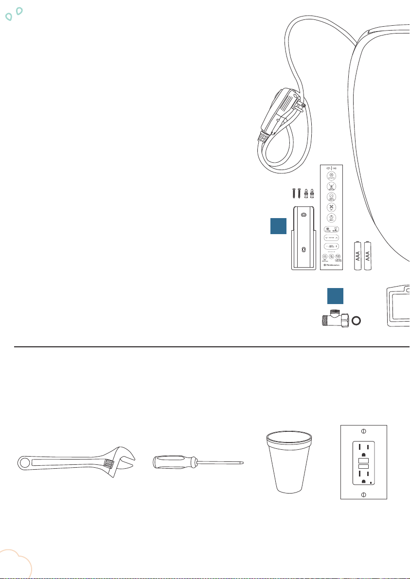
What’s In The Box:
A. 1x - Soft Spa 9500
B. 1x - Remote w/ holder
2x - ¾" screws with anchors
2x - AAA Batteries
C. 2x - Double bump grommets
2x - Sliding rails
2x - 2 ½" stainless steel mounting screws
2x - 2 ½" stainless steel hexnut mounting screws (optional)
2x - Wingnut and washer (optional)
D. 1x - Seat template
E. 1x - T-valve
1x - Rubber washer
F. 1x - Mounting Plate
G. 1x - 20" Supply line connector
H. 1x - 16" Supply line connector
I. 3x - Threaded supply line adaptors
B
E
Additional Items You’ll Need:
For Soft Spa 9500 bidet seat:
A:Rear edge of area A is not allowed
to touch the tank;
B:Area B must cover the edge of the
ceramic (Ceramic is invisible)
C:Area C aligns the fixing plate。
Area A is folded =
No Good
Area C aligns the fixing plate = OK
The edge of ceramic is visible =
No Good
RESET
RESET
TEST
TEST
Crescent Wrench Flathead screwdriver
(5/32" size recommended)
Disposable cup
filled with water
A ground fault
120-volt outlet
A:Rear edge of area A is not allowed
to touch the tank;
B:Area B must cover the edge of the
ceramic (Ceramic is invisible)
C:Area C aligns the fixing plate。
Area A is folded =
No Good
Area C aligns the fixing plate = OK
The edge of ceramic is visible =
No Good
RESET
RESET
TEST
TEST
A:Rear edge of area A is not allowed
to touch the tank;
B:Area B must cover the edge of the
ceramic (Ceramic is invisible)
C:Area C aligns the fixing plate。
Area A is folded =
No Good
Area C aligns the fixing plate = OK
The edge of ceramic is visible =
No Good
RESET
RESET
TEST
TEST
A:Rear edge of area A is not allowed
to touch the tank;
B:Area B must cover the edge of the
ceramic (Ceramic is invisible)
C:Area C aligns the fixing plate。
Area A is folded =
No Good
Area C aligns the fixing plate = OK
The edge of ceramic is visible =
No Good
RESET
RESET
TEST
TEST

9
A:Rear edge of area A is not allowed
to touch the tank;
B:Area B must cover the edge of the
ceramic (Ceramic is invisible)
C:Area C aligns the fixing plate。
Area A is folded =
No Good
Area C aligns the fixing plate = OK
The edge of ceramic is visible =
No Good
RESET
RESET
TEST
TEST
A
C
D
F
G
H
For Remote Control Mount Installation – page 25:
I
Drill with a 3/16"
drill bit
Hammer Phillips head drill bit or
screwdriver
A:Rear edge of area A is not allowed
to touch the tank;
B:Area B must cover the edge of the
ceramic (Ceramic is invisible)
C:Area C aligns the fixing plate。
Area A is folded =
No Good
Area C aligns the fixing plate = OK
The edge of ceramic is visible =
No Good
RESET
RESET
TEST
TEST
A:Rear edge of area A is not allowed
to touch the tank;
B:Area B must cover the edge of the
ceramic (Ceramic is invisible)
C:Area C aligns the fixing plate。
Area A is folded =
No Good
Area C aligns the fixing plate = OK
The edge of ceramic is visible =
No Good
RESET
RESET
TEST
TEST
A:Rear edge of area A is not allowed
to touch the tank;
B:Area B must cover the edge of the
ceramic (Ceramic is invisible)
C:Area C aligns the fixing plate。
Area A is folded =
No Good
Area C aligns the fixing plate = OK
The edge of ceramic is visible =
No Good
RESET
RESET
TEST
TEST

10
Prep! Before Installing:
1. Turn off your water supply shut-off valve and drain the tank by flushing the toilet.
2. Place a towel on the floor, under the supply line connector.
3. Remove the old supply line connector.
4. Remove your existing toilet seat.
5. Clean the surface of the bowl around the mounting screw holes.
6. Prepare and organize the install tools and components.
B
C
E
F
G
H
I
11
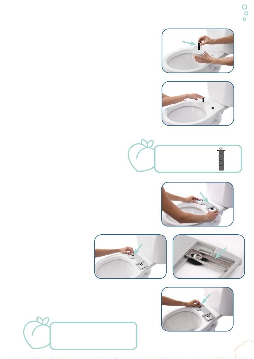
A.
Dunk grommets (C), with screws, in a cup of water before
inserting them for easier installation.
Step 1: Install Mounting Plate
B.
Insert skinny side of double bump grommets (C) with screws
into the seat holes and pull from the bottom while applying
pressure to the top. Once inserted, remove screw and reserve
for Step 2E.
Alternative method: Go bottoms up! Push the
top of the grommet through the bottom of the
hole on the underside of your toilet. If you are
still having issues, see page 27.
C.
Place mounting plate (F) on top of grommets.
D.
Align the center of each sliding
rail (C), flat side down, over the
grommet hole by placing it in the
mounting plate slot.
E.
Secure sliding rails by inserting screws (C) through the
grommet hole, and loosely tighten with screwdriver.
Correct!
(C)
(F)
(C)
(C)
P
e
a
c
h
T
i
p
!
Top
Bottom
Keeping the screw in
the grommet will
make insertion easier!
P
e
a
c
h
T
i
p
!
Mounting plate should be firmly
attached but able to move
slightly with screws in place.

12
Step 2: Bidet Alignment
Keep tightening… Getting closer… You did it!
A.
Place template (D) onto the bowl, fitting snuggly against
the bottom edge of the mounting plate.
B.
Slide mounting plate forward or backward until the front
edge of the template lines up with the front edge of the
toilet rim.
C.
Once aligned, secure mounting template in place by
tightening screws until the mounting plate no longer slides,
and screws and grommets look like below.
If screws won’t fully insert to appear like above, make
sure that the sliding rails are placed flat-side down in
the mounting plate slot. See Step 1D on page 11.
(D)
13
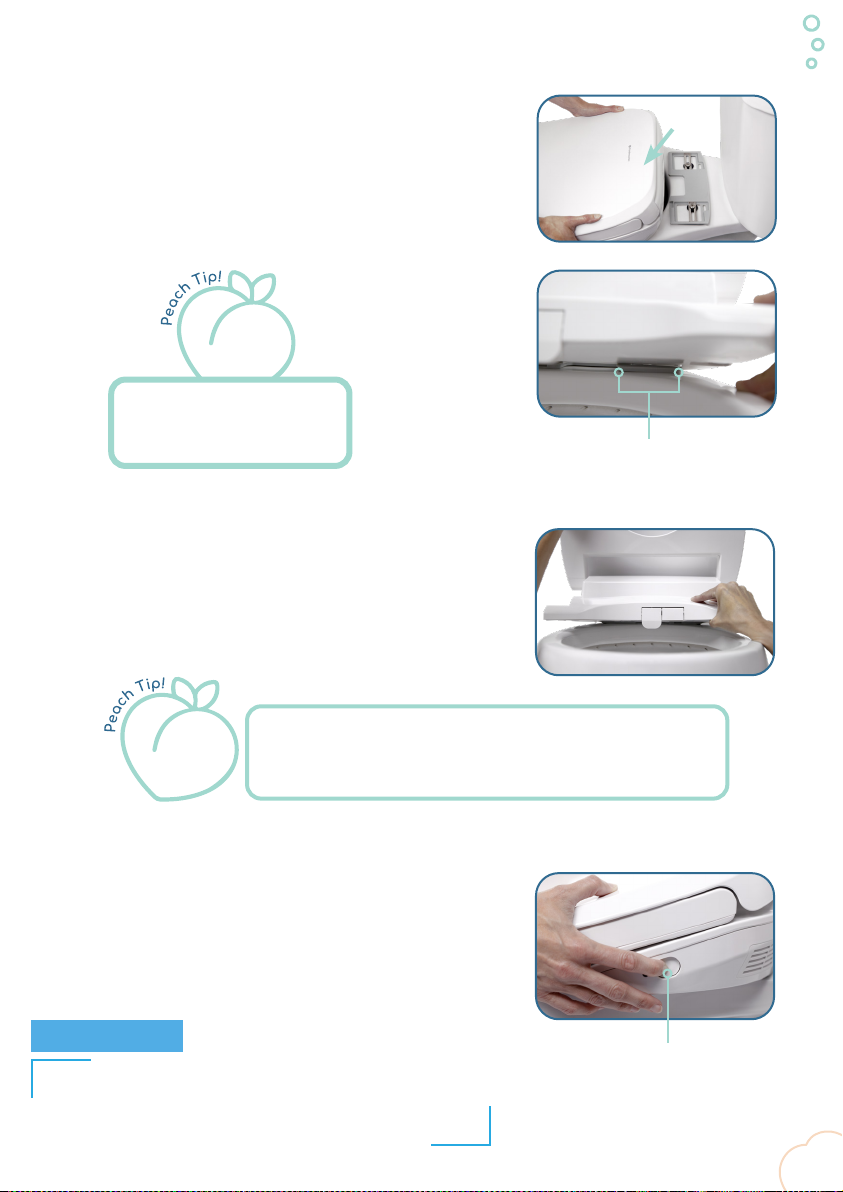
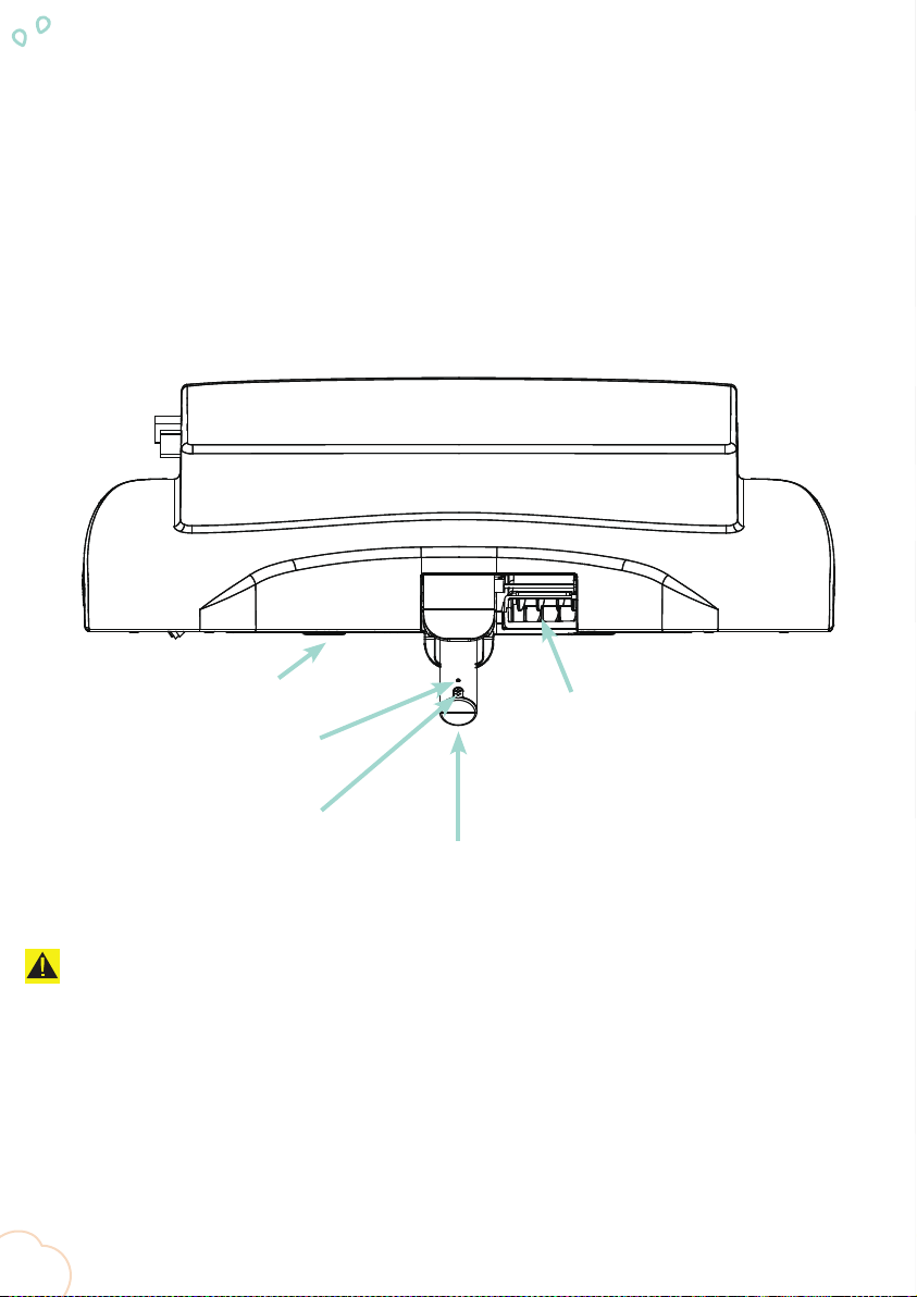
Step 3: Attaching the Bidet
Quick-Release Button
A.
Remove template and place the bidet (A) onto the bowl,
aligning the channel under the bidet base with the
mounting plate.
B.
With the lid and the seat in the up position, slide the base of
the bidet back onto the mounting plate until you hear a “click.”
C.
Double check that the bidet is secure and aligned to your
desired placement. If adjustment is needed, remove the bidet
by pressing the quick-release button on the right side of the
base and sliding the bidet off the toilet.
If you don’t hear an audible “click,” make sure that the
screws are flush with the mounting plate and that the sliding
rails were installed correctly. See Step 1D on page 11.
Channel
Proper alignment is easiest
to see while at eye-level
with the mounting plate.
Pull ONLY from the base. DO NOT pull the seat or lid, as this
could damage the unit.
Return to Step 2A on page 12 to find proper placement.
NOTICE
(A)

14
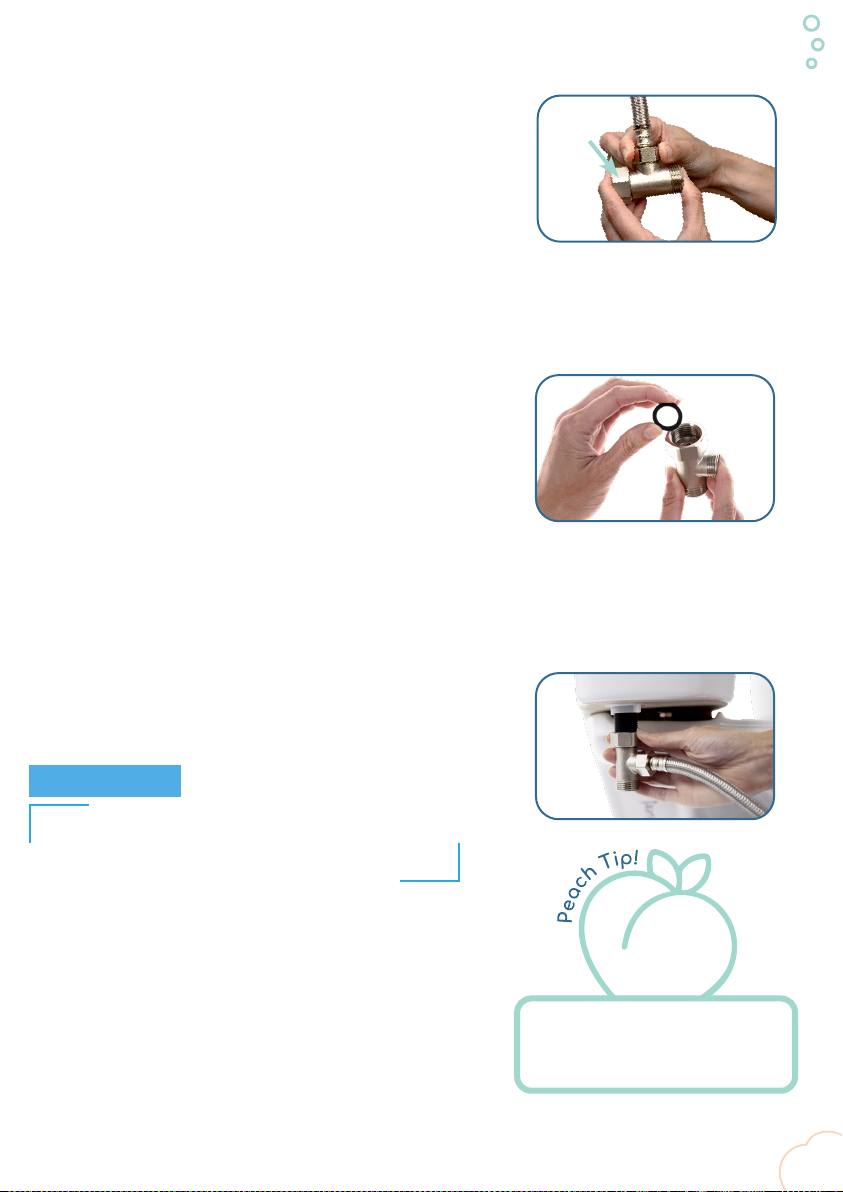
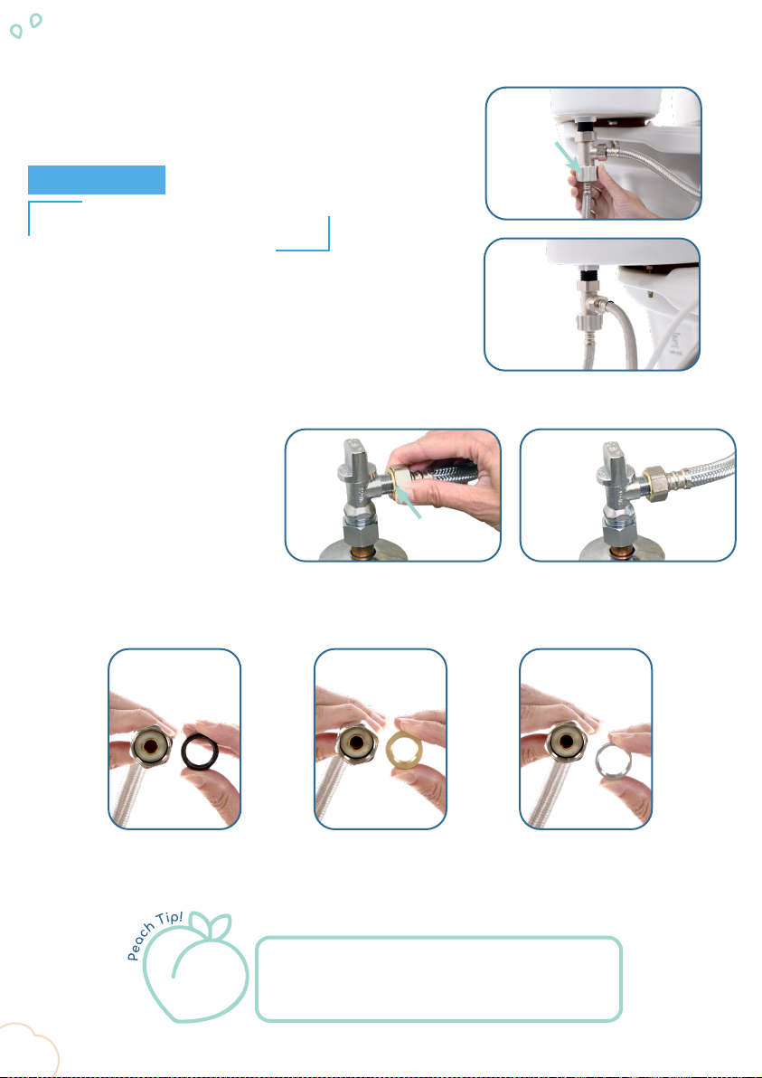
Step 4: 16" Supply Line Connection
A.
Remove the bidet using the quick-release button on the
right side of the base.
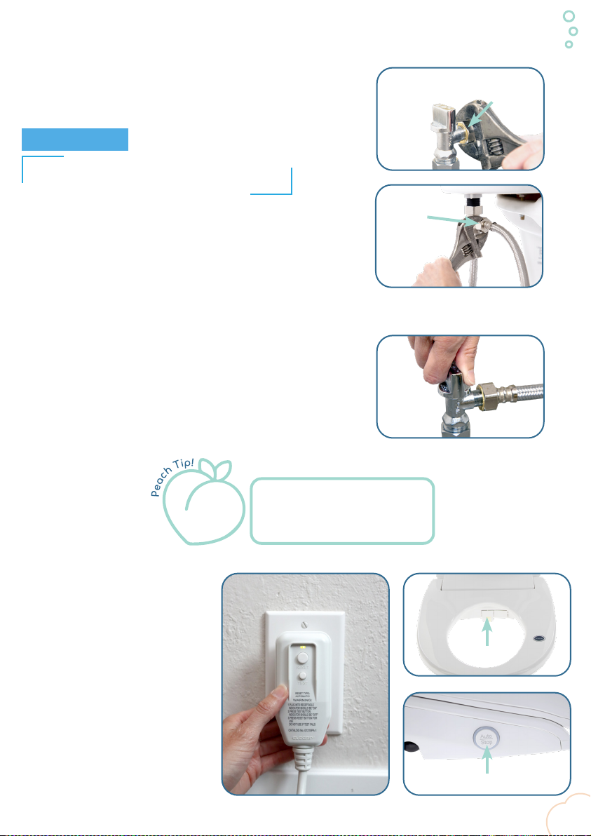
D.
Tighten ½ turn past hand tight with a crescent wrench to ensure
the connection is secure.
Overtightening could cause damage and lead to failure of the
nut. Such damage may not be visible to the eye. Failure of the
nut can lead to significant water leakage and water damage.
C.
Secure the 16" supply line connector (H) by threading the
metal nut onto the external valve.
B.
Locate the external valve on the
left side of the bidet. Rotate it
out of the recessed position and
remove the valve cap.
E.
With the supply line connector securely attached, rotate
the valve to its original position, and remount the bidet
onto the mounting plate on your toilet; see “Steps 3A
and 3B” on page 13.
Pull ONLY from the base. DO NOT pull the
seat or lid, as this could damage the unit.
NOTICE
DO NOT OVERTIGHTEN.
NOTICE
(H)
15
Step 4: 16" Supply Line Connection (cont).
F.
Attach the middle opening of the T-valve (E) to the
opposite end of the 16" supply line connector that you just
secured to the bidet until hand tight.
H.
Secure the metal nut of the T-valve onto the external fill
valve thread on your toilet and hand tighten.
Overtightening and/or the use of tools could cause damage
and lead to failure of the nut and/or fill valve. Such damage
may not be visible to the eye. Failure of the nut and/or
fill valve can lead to significant water leakage and water
damage.
G.
Place the rubber washer into the T-valve, making sure that
it is flush to the opening.
DO NOT OVERTIGHTEN. DO NOT USE TOOLS WHEN
TIGHTENING NUT TO PLASTIC FILL VALVE. DO NOT
USE TEPHLON TAPE.
NOTICE
For the best install, clean the
threads of your fill valve with a
towel before attaching T-valve.
(E)
16
Step 5: 20" Supply Line Connection
Black = 3/8"Bronze = 7/16"Silver = 1/2"
B.
Thread the metal nut on the
opposite end of the 20" connector
onto the water supply valve until
hand tight.
If your water supply valve is
not ½", use one of the included
threaded adapters (I).
A.
Align threads of the plastic nut on the 20" connector (G) onto
the bottom opening of the T-valve using only your hands.
Overtightening and/or the use of tools could cause damage and
lead to failure of the nut. Such damage may not be visible to the
eye. Failure of the nut can lead to significant water leakage and
water damage.
Choose the correct adapter by first attaching it to
the water supply valve then inserting the adaptor
thread-side first into the supply line connector nut.
DO NOT OVERTIGHTEN.
DO NOT USE TOOLS ON PLASTIC NUT.
NOTICE
(I)
(G)
17
Step 6: Finishing Touches
A.
Using a wrench, tighten all metal-to-metal connections ½ turn
past hand tight.
Overtightening and/or the use of tools could cause damage and
lead to failure of the nut and/or fill valve. Such damage may not
be visible to the eye. Failure of the nut and/or fill valve can lead
to significant water leakage and water damage.
B.
Slowly turn the water supply on and check for leaks at the valve.
C.
Once all supply lines are securely
installed, remove the tape from
the wand cover, and plug in your
bidet. Check that the light on the
left side of bidet base marked
“AUTO/STOP” comes on.
See page 23 for plug description
and specifications.
Metal-to-
Metal
Metal-to-
Metal
Tape
Auto/Stop
Touch a paper towel to water
connection points to check for
slow, unassuming leaks.
DO NOT OVERTIGHTEN. DO NOT USE TOOLS ON
PLASTIC NUT OR PLASTIC FILL VALVE.
NOTICE
18
Night Light
Rear Wash
Front Wash
Warm Dry
Nozzle
Bidet Function Test:
1. Make sure that both your water supply and power to the unit are turned on.
2. Have a disposable cup ready to hold upside down over the nozzle of the extended wand to
prevent water spray.
3. Gently press the blue sensor on the right side of the seat with your hand.
4. While sensor is activated, press the “REAR” and “FRONT” cleaning buttons on the remote to
ensure proper nozzle function. See remote guide on page 20.
CAUTION:
Read carefully the following information on the seat temperature level indicator light, water
temperature level indicator light and alarm functions.
If any of these issue occur, please immediately cut off the power supply, and contact Fluidmaster
Technical Services (800-631-2011) for further assistance.
1. The power indicator light on the product flashes.
2. The leakage protection switch of the power plug frequently trips.

• See troubleshooting on Page 27 if needed.
Congrats, You’re Finished!
Welcome to the Peachy Clean Life!
Happy Bum. Happy Life.
YOU DID IT!
We knew you could!
Share your success story with friends and family!
#HappyBum
#PeachyCleanLife
#Fluidmaster

20
Remote Control Functions:
DRY TEMPERATURE
SEAT TEMPERATURE
POSITION
DEODORIZER
GENTLE
DRY
FRONT/OSCILLATE
REAR/OSCILLATE
AUTOMATIC WORKING MODE/
STOP
WATER TEMPERATURE
INDICATION LIGHTS
NIGHT-LIGHT
WATER PRESSURE
Your Soft Spa 9500
will keep the last
used settings until
manually changed.
Table of contents
Other Fluidmaster Toilet manuals


Popular Toilet manuals by other brands


Drive
Drive TSE 150 operating instructions

Clou
Clou Hammock CL/04.01081.01 installation instructions

fine fixtures
fine fixtures MOTB10W installation instructions

NATURE LOO
NATURE LOO NL3 owner's manual

noken
noken VITAE 100183297-N372769945 manual

Swiss Madison
Swiss Madison Monaco SM-1T109 installation instructions


