Fluiteco SMC04 User manual

FLUITECO SMC 1
OPERATION AND MAINTENANCE USER
MANUAL
SMC –SUB-VERTICAL BAR SCREEN
INDEX
Rev 04
27/08/2020

FLUITECO SMC 2
INDEX
1. INTRODUCTION................................................................................................ 4
2. PREFACTION..................................................................................................... 4
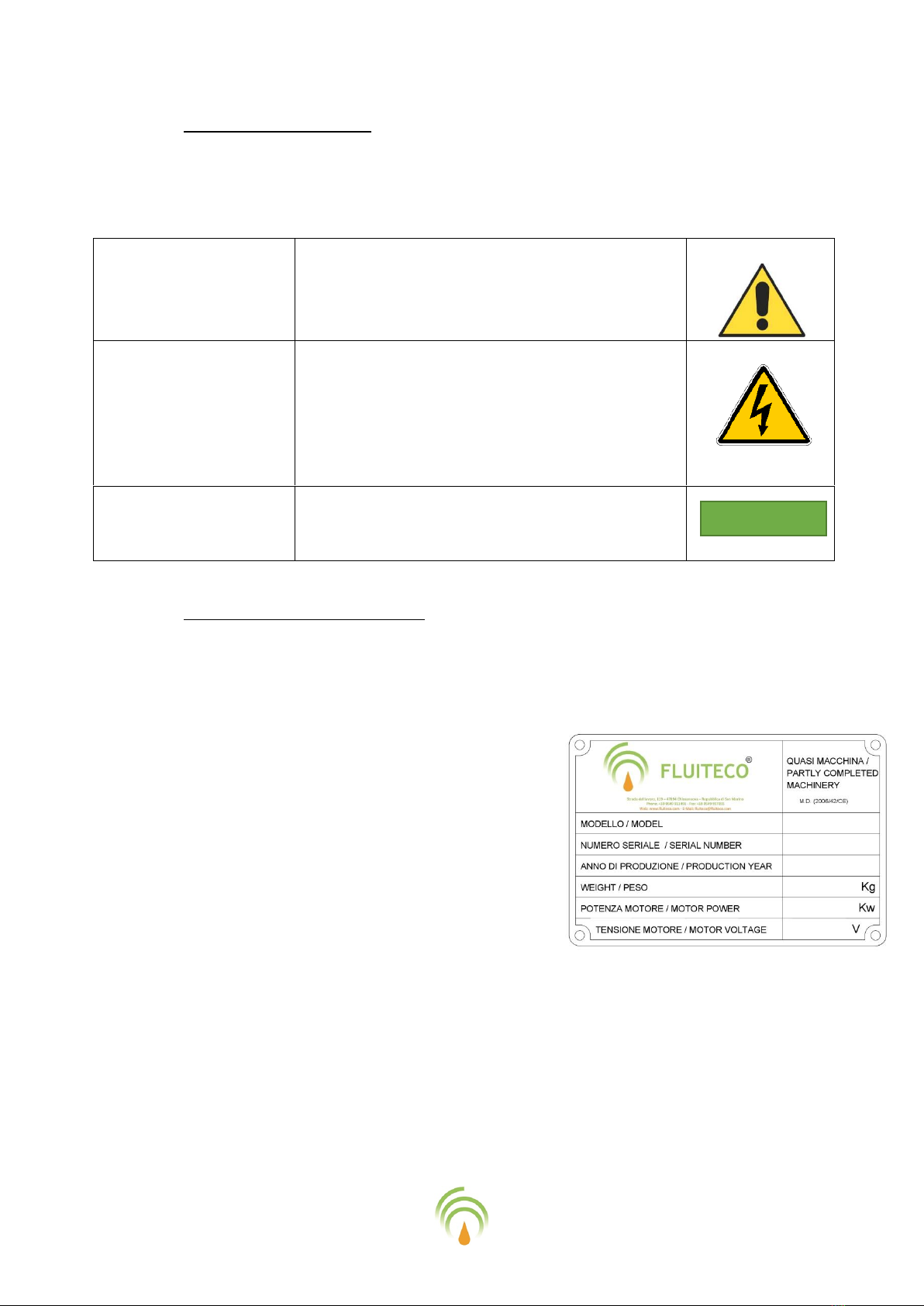
2.1 Symbology of warning...........................................................................................................5
2.2 Identification of the machine................................................................................................5
2.3 Guarantee..............................................................................................................................6
2.4 Manufacturer’s declaration (Type A) Machine.....................................................................6
2.5 Technical service ...................................................................................................................6
3. RECEIVING AND INSTALLATION........................................................................ 7
3.1 Purpose..................................................................................................................................7
3.2 Conditions on the usage limits..............................................................................................7
3.3 Unloading ..............................................................................................................................7
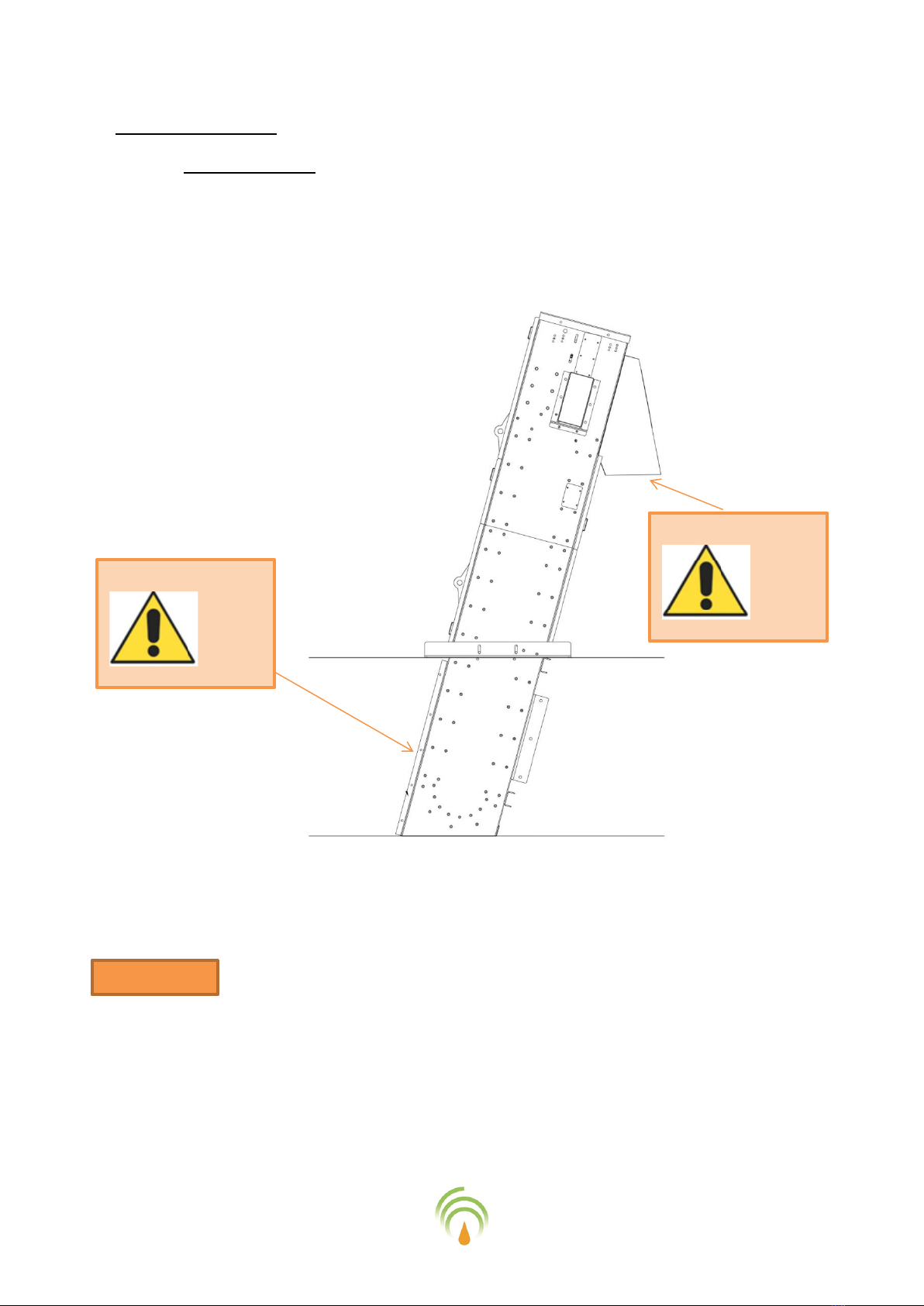
3.4 Installation procedure...........................................................................................................8
4. SECURITY NORMS .......................................................................................... 10
4.1 Improper usage ...................................................................................................................10
4.2 Safe usage............................................................................................................................11
4.3 Individual safety devices .....................................................................................................12
4.4 Plant’s safety devices ..........................................................................................................12
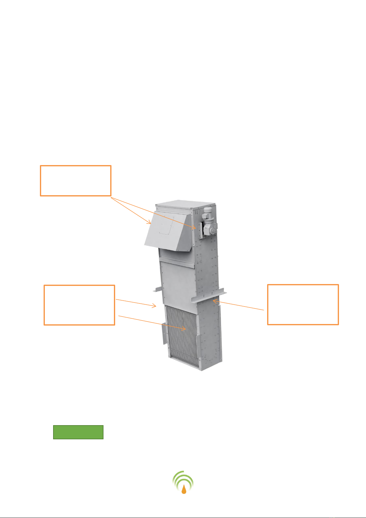
5. DESCRIPTION AND CHARACTERISTICS ............................................................ 13
5.1 Proper usage and description of the working process........................................................13
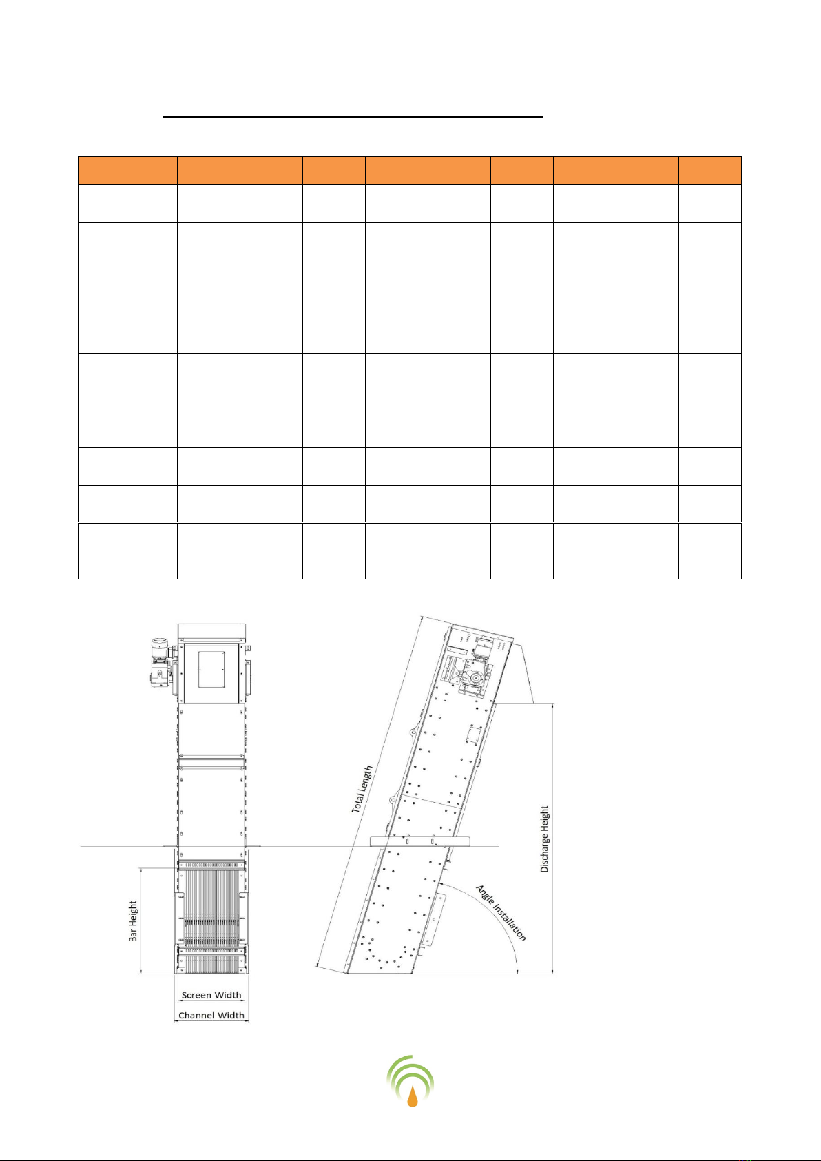
5.2 Dimensional characteristics of the standard models..........................................................14
5.3 Characteristics of the effluent that can be dealt with ........................................................15
6. USAGE OF THE MACHINE ............................................................................... 15
6.1 Starting procedure ..............................................................................................................15
7. ORDINARY MAINTENANCE............................................................................. 17
7.1 Safety conditions in case of maintenance...........................................................................17
7.2 Cleaning...............................................................................................................................17
7.3 Periodic check......................................................................................................................17
7.4 Special maintenance ...........................................................................................................19
7.4.1 Replacement of the gearmotor ...................................................................................19
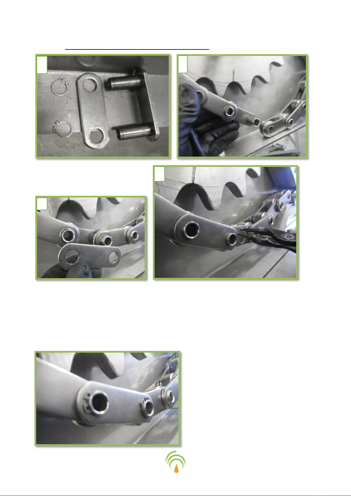
7.4.2 Replacement of chain ..................................................................................................19

FLUITECO SMC 3
7.4.3 Removal and repositioning of the connecting link......................................................20
7.4.4 brushes’ Replacement..................................................................................................21
7.4.5 Replacement of the wearing plates.............................................................................21
7.4.6 Replacement of the wearing process’ brush ...............................................................21
7.5 How to order the replacement parts ..................................................................................22
8. END OF THE OPERATIONAL CYCLE.................................................................. 22
8.1 Long period stockages.........................................................................................................22
8.2 Demolition of the machine..................................................................................................22
9. ANNEX ........................................................................................................... 23
10. TROUBLESHOOTING....................................................................................... 24
11. OPTIONAL : TORQUE ARM ............................................................................. 25
11.1 Torque arm –Why is needed ..............................................................................................25
11.2 Torque arm –Our implementation.....................................................................................25
11.3 Torque arm - Principle of functioning .................................................................................26
11.4 Torque arm –Exploded view, Sections and Bill of material................................................27
11.4.1 Torque arm –Explode view .........................................................................................28
11.4.1 Torque arm –Sections .................................................................................................29
11.4.2 Torque arm –Bill of Material.......................................................................................31
11.4.3 Torque arm –Troubleshooting....................................................................................32

FLUITECO SMC 4
1. INTRODUCTION
Before proceeding with any operation, read carefully the present manual as to avoid any
unplanned event and/or mistaken usage of the machine. The present manual of usage and
maintenance is part of the technical documentation given together with the machine and its
purpose is to give all the necessary information for a correct and safe usage of the machine
2. PREFACTION
The following manual describes the principals behind the working process of the machine, based
of the following premises :
•Fluiteco S.r.l. keeps the right of making modifications to its products whenever and without
warnings.
•The present manual cannot be sold / given to others without the authorisation of Fluiteco
S.r.l.
•This manual is lied to the sale of this machine and must always be present in this factory , in
case of damaging or unreadability we plead you to request a copy
•The machine must only be used for the purposes Fluiteco S.r.l. built it for, every other usage
can be considered dangerous and improper. Fluiteco S.r.l. doesn’t assume any of the risks
caused by the inaccurate use of the machine
•Every action or intervention that modifies the structure of the machine must be done with
the accordation from Fluiteco s.r.l.
Fluiteco S.r.l. doesn’t assume the risks caused by the improper modifications not accorded with
the technical division of Fluiteco s.r.l.
•Always use the original Replacement objects Fluiteco s.r.l.
Fluiteco S.r.l. has no responsibilty in case of damages to human beings, animals or objects, caused
by the fixingof not original Replacement objects.
Attention !
Attention !

FLUITECO SMC 5
2.1 Symbology of warning
During the read of the manual you will meet with various types of simbols: the correect
interpretation is as illustrated in the following chart.
WARNING OF GENERAL
DANGER
This type of warning shows the dangers for the
people working in the implant. Whenever this
symbol is present, the employees might get hurt.
DANGER WARNING
CAUSED BY HIGH
VOLTAGE
This type of warning idicates the presence of high
voltage. Before executing any action on the
machine, cut the voltage by operating on the
power lever.
ATTENTION WARNING
This symbol warns one to pay attention to the
following words.
2.2 Identification of the machine
The machine is identified by the plate, here sapresented and described. The plate is easily
identified on the metal structure and is generally positioned in an easily spottable location. La
targhetta riporta le seguenti diciture:
1) Name and headquarter of the constructor
2) Machine’s model;
3) Serial number;
4) Year of construction
5) Power
6) Weight
The information on the plate cannot be changed.
When contacting out technical services, we beg you to always communicate the model and the
matriculation number of the machine
Attention !

FLUITECO SMC 6
2.3 Guarantee
Fluiteco S.r.l. guarantees that the machine was tested in every safety and functional.
The duration time of the guarantee is shown on the contract and refers to the mechanical
components that the constructor offers himself to substitute for free. The electric motor, eventual
electric and electronics defects caused by external factors are not imputable to Fluiteco S.r.l.
A mistaken maintenance or an improper utilisation of the machine causes the degeneracy of the
Guarantee.
Every alteration of the product, in particular on the protective gear/devices, will make the
guarantee decade and free the constructor from every responsibility.
2.4 Manufacturer’s declaration (Type A) Machine
The machine is constructed upon the directive 2006/42/CE and its successive versions. The
machine is destined to be incorporated in a factory based upon the needs of the installation.
2.5 Technical service
To obtain the best performance of the machine and avoid any problem that could cause the
degeneration of the guarantee, following the sequent warnings reported in the manual.
This manual of use and maintenance is a fundamental part of the machine and must be easily
accessible by all of the qualified employees. In case of malfunctioning, the present manual can
help understanding the problem and, after consulting the necessary controls, it might be
necessary to call the technical service of Fluiteco. Upon contacting the technical service , always
provide the model and matriculation number of the machine; these information are written in a
complete and exhaustive manner on the identification plate on the machine.
Attention !

FLUITECO SMC 7
3. RECEIVING AND INSTALLATION
3.1 Purpose
The system SMC –SUB –VERTICAL BAR SCREEN is destined to be installed only inside the
channels having dimensions as confirmed in our dimensional drawing sent to you for approval.
Machine SMC is destined to be installed inside the channel with effluent to screen. The machine
must be fitted on the bottom of the channel and must be fixed also on the lateral floor of the
channel.
3.2 Conditions on the usage limits
The optimal temperature of the machine is between 0°C and 50°C as the formation of ice inside
the machine causes defects in the whole machine; the same thing can happen when the
temperature is too high.
In ice-stricken areas the machines without a proper temperature-regulating device must be put
inside of a proper building, so that the machine can operate without problems and in optimal
conditions.
The formation of ice inside of the machine can cause the malfunctioning of the entire system.
Fluid typology : water with screened substances
3.3 Unloading
Unloading and positioning of the machine must be carried out with a discharge device appropriate
to the weight and size of the machine (for the weight of the machine refer to the details on the
rating plate ).
The lifting of the machinery must only be on the eyebolts attached to the machine.
Connect to these eyebolts exclusively with hooks with safety latch.
And 'forbidden to use hooks, open rings or other lifting systems that do not guarantee safety in
lifting operations or the flow required.

FLUITECO SMC 8
3.4 Installation procedure
a) Before proceeding with the installation it is suggested previewing the adequate handling
places around the machine to facilitate the maintenance.
b) Lift the machine using the lifting ringbolts as shown in chapter 2.3.
c) Lower the machine until it reaches the pavement inside the cement (1)
a) Once the machine is correctly positioned, regulate the adherence of the upper angular
fixings (1) through the loops and fix them with mechanical plugs or threaded rods with
chemical anchorage.
b) Fix the machine on the bottom of the outlet through the asolar holes positioned on the
bottom of the machine
c) Regulate the adherence of the rear angular fixings (2) though the loops and fix them with
mechanical plugs or threaded rods with chemical anchorage on the lateral sides of the canal.
d) Regulate the adherence of the frontal angulars (3) through the loops and fix them with
mechanical plugs on the lateral parts of the canal. .
e) Assemble the discharge slide with fixings bolts

FLUITECO SMC 9
1. Angular support
for top fixing
3. Angular support
for ground level
fixing
2. Angular support
for back fixing on
the wall
Attention !

FLUITECO SMC 10
4. SECURITY NORMS
4.1 Improper usage
The machine is provided with every protection necessary, however there are zones in the machine
that can be protected only with the ambient of the implant where it is installed. Such fundamental
protection is the installer’s and the customer’s responsibility.
It’s responsibility of the final customer providing with the adequate devices the safety of his
employees.
Discharging exit
Inlet screening zone
Attention !

FLUITECO SMC 11
4.2 Safe usage
To avoid any kind of incident, read carefully the following information.
•The machine can only be used by the authorised personnel.
•The machine can not be utilised for a purpose that differs from the customer’s original
request.
•All the junctions must be made by the authorised personnel.
•Effectuate a correct fissage between the different machine’s units and a correct junction
at the stamping floor.
•When the machine is in function the employees must remain at a safe distance from it.
•Before starting the machine carefully check if all the safety devices are connected and
that the machine is in perfect conditions.
•In case of any defect , in particular on the safety devices, the operator must inform his
superiors, the safety accountable and the operator of the eventual successive shift.
•If the defect doesn’t let the machine perform at 100%, the machine has to be stopped.
•It’s forbidden to remove the protections and the security devices close to the machine.
•Every control, maintenance ecc… must be done by the authorised personnel.
•The authorised personnel must wear suitable clothes. Ask for the safety accountable
about the supply of such equipment ( shoes, gloves, ecc….. )
•Unplug the high voltage before effectuating any operation / maintenance of the
machine.
•To avoid any accidental starting of the machine during inspections, cleaning, or
maintenance, position the switch in the OFF position and press the emergency button.
•Before activating the machine be sure that all safety devices are functional.
•Fluiteco S.r.l. denies any responsibility for damages to objects , human being and animals
caused by the absence of maintenance of the machine.
•It is of absolute importance keeping the implant and the machine under control with
frequent inspections ( 1 every day ) as to notice instantly any type of malfunctioning.
•Whenever anomalies occur, turn off the implant as it could cause danger for your safety
and that of the factory.
•Make sure that the identification plate is easily readable.
•Having the junction on the ground close to the machine is mandatory.
•Removing the danger plates next to the machine is forbidden.
•Removing or opening the safety devices during the functioning of the machine is
forbidden.

FLUITECO SMC 12
4.3 Individual safety devices
The operator responsible for the supervision of the implant must have every safety device on him
(gloves, shoes, ecc… ).
Once the machine starts, it emits a high-sounding pressure that might damage the hearing, as
such the use of soundproof earplugs is highly recommended.
N.B.: THE EVALUATION OF THE SOUND PRESSURE MUST BE DONE
BY THE COMMISSION UPON THE INSTALLATION.
4.4 Plant’s safety devices
Every implant must be provided with an emergency button to stop the machine in case of
emergency. By pressing such button, the machine stops itself, in case of dangerous situations in
the implant.
The emergency button must always be in close proximity to the machine and must always be
easily accessible. It’s the reasonability of the installer to assure the presence of all the necessary
protection gear and to guarantee the safety of the implant.
OTHER RISKS
The following chart resumes the risks and how to reduce them.
Images
Description
Protection measures
The machine has parts moving that
might cause lesions.
Doing maintenance while maintenance
is on is strictly forbidden.
The machine must have an electric
system of its own with the removal of
specific parts it must be possible to
have access to high tension zones.
Turn off the power supply before every
operation. Only authorised personnel
can have access to junctions electrically
connected.
Danger caused by possible falling
pieces
In the proximity of the machine the
pavement might be unstable because of
water losses. Take every step carefully,
it can be slippery.

FLUITECO SMC 13
5. DESCRIPTION AND CHARACTERISTICS
5.1 Proper usage and description of the working process
The SMC is a machine invented to screen the wastewaters coming from the industrial and
municipal implants, screening the bigger and smaller particles ( until 66 mm of speckles ), bringing
them towards the bottom of the canal though one or two brushes ( the quantity can variate
depending on the lenght of the machine ) and expelling them through the discharge outlet in the
proper filler chosen by the customer .
Direction of the water in the discharge
outlet of the canal
brushes’ movement
screened substances’ discharge
direction of the filtered waters
Every other use of the machine will automatically determine the loss of the guarantee and
relieves Fluiteco s.r.l. from every responsibility in case of damages to objects, animals or human
beings.

FLUITECO SMC 14
5.2 Dimensional characteristics of the standard models
MODELLO
SMC04
SMC06
SMC08
SMC10
SMC12
SMC14
SMC16
SMC18
SMC20
Canal width
(mm)
400
600
800
1000
1200
1400
1600
1800
2000
*total length
Lu (mm)
3350
3350
3350
3550
3550
3550
3550
3550
4050
**discharge
outlet’s
height (mm)
2300
2300
2300
2500
2500
2500
2500
2500
3000
Total width
(mm)
370
570
770
970
1170
1340
1540
1740
1940
Rods height
(mm)
600
600
600
800
800
800
800
800
1300
Rods
distance
(mm)
6 - 60
6 - 60
6 - 60
6 - 60
6 - 60
6 - 60
6 - 60
6 - 60
6 - 60
*quantity of
brushes (n°)
2
2
2
2
2
2
2
2
2
*** engine’s
power (kw)
0,55 - 3
0,55 - 3
0,55 - 3
0,55 - 3
0,55 - 3
0,55 - 3
0,55 - 3
0,55 - 3
0,55 - 3
****
installation’s
angulation
75°
75°
75°
75°
75°
75°
75°
75°
75°

FLUITECO SMC 15
Lateral supports to fix the the unit to the canal are always included
* every 1000 mm of extra length, a brush is added (maximum of 6 )
** from the bottom of the canal.
***power calculated keeping in consideration the height of the machine and the type effluent that
has to be removed **** standard inclination
5.3 Characteristics of the effluent that can be dealt with
The functioning, efficiency, and in some cases the integrity of the machine can be mined if it is
used to filter the wastewater that present these anomalies:
•The screened substances, sands and grease cannot be mechanically separated from the
liquid.
•The screened substances, sands and grease agglomerate between them or parts of the
machine.
•The screened substances, sands and grease crust (by themselves or attaching to some parts
of the machine),
•The screened substances, sands and grease chemically react between them (polymerizing
ecc.),
•The wastewater tends to freeze.
•The wastewater have an excessively corrosive and acid PH
In case that the screened materials agglomerate and encrust themselves, it must be possible to
remove the solid substances from the machine’s elements through high-pressure water jets .
6. USAGE OF THE MACHINE
6.1 Starting procedure
Before proceeding with the start/stop of the machine, check if every impediment condition were
eliminated. Also check if every safety device is fully operational.
- verify if external substances or water infiltrated the machine; in such cases, remove the coating
and clean.
-verify that every blockage system utilised for transport were removed.
- verify if the engine conditions are correct, and that it wasn’t subjected to any damages during
transport and installation.
- verify that every electrical junction was made in a correct way, and that there aren’t any open
boxes, wires ecc. ecc.

FLUITECO SMC 16
- verify the correct functioning of the emergency button close to the outlet.
-verify that the charge and discharge areas were adequately marked and delimitated and
highlighted by the proper warning signals.
- verify that the danger signals were placed on the machine.
- control the correct fixage of the machine and verify its stability .
- verify the correct functioning of the auxiliary functions, such as cleaning alimentation.
FIRST START
The first test after the installation must be effectuated with an empty machine for approximately 2
minutes .
verify that:
- there are no anomal noises .
- there are no vibrations .
- that the machine is stable .
if everything works correctly, proceed with the waste filtration .
if necessary make some adjustements and/or maintenance, it is fundamental unplugging the
alimentation before operating .
- verify that the screw screen rotates in a counter-clockwise manner. If not, invert the junction in
the engine.
- make sure that the oil in the reductor is at an acceptable level.
OPERATIONS
After the first 12 hours of working control the following points :
- the clamping of the bolts.
- the support ‘s conditions.
- the engine’s temperature.
- the oil level in the gear .
depending on the installation , the functioning of the machine can be controlled by a control
panel in close proximity of the machine or a remote control .
- in case of a long period of inactivity, stop the reflux from entering and wash the machine. It is
important because the transported material tends to harden up after long periods of stillness.

FLUITECO SMC 17
7. ORDINARY MAINTENANCE
This chapter gives the necessary instructions to effectuate the standard maintenance that does
not require special operations from the employee.
BEFORE ANY OPERATION MAKE SURE THE ELECTRICAL CURRENT IS UNPLUGGED .
N.B.for what regards the lubrification of the engine and the gearbox it is recommended looking at
the catalogue of gearbox and motor manufacturer.
7.1 Safety conditions in case of maintenance
The machine’s maintenance must only be effectuated by authorised personnel.
Before proceeding with any type of maintenance, stop the alimentation and unplug the electric
units.
To maintain the performance to 100%, it is recommended using only the original replacement
parts.
The assembly of not original replacement parts will automatically decadate the guarantee and
exents Fluiteco s.r.l. from any responsibility in case of damages to objects, animals or human
beings.
7.2 Cleaning
Before doing any cleaning operations (internal or external) unplug all electric devices.
Also remove eventual obstructive elements, activating all carters and existent protections.
7.3 Periodic check
It is possible to divide the necessary controls in two parts :

FLUITECO SMC 18
Controls necessary in the first 10 hours of working :
1. Periodic controls :
Description
Period
Control the correct voltage in the chains that move the brushes
Inside the first 10 hours of
work
Electric engine and gear box : verify the absence of excessive
noise
Inside the first 10 hours of
work
Description
Period
Check the correct lubrification of the brush –cleaning support
If necessary lubrificate with the proper greaser
Every two months
Description
Period
Vcheck the correct lubrification of the main engine
If necessary lubrificate with the proper greaser
Every two months
Description
Period
Check the correct functioning of the electric engine
Every month
Check the correct functioning of the gear box
Every month
Check the correct functioning of the brush-cleaner and the usury
state of the cleaning part made of high-density plastic material.
Every six months
Check the usury state of the chains made of high-density plastic
material
Every six months
Check the movement of the chains and verify the correct voltage
Every month
Greaser
Greaser

FLUITECO SMC 19
7.4 Special maintenance
Instructions on special maintenance can be found in the following pages in case of a high usury
level.
It is recommended, before executing any operation, to thoroughly clean the machin .
Always pay the maximum amount of attention during the maintenance and the relocating of the
machine. Follow closely the security norms shown in the past chapters.
7.4.1 Replacement of the gearmotor
1. Unscrew the bolt A;
2. Unscrew the bolt B;
3. extract the gearmotor; B
4. position the new gearmotor; C
5. Disassemble from the old gearmotor
the hob C and fix it on the new one;
6. Screw bolt Aand bolt B
A
7.4.2 Replacement of chain
1. Disassemble the cover plate A; A
2. Disassemble the upper cover plate B;
3. Remove the connecting link (7.4.3);
4. Unstring the chain that has to be replaced;
5. Position the new chain in its proper place
6. make it circulate and then mount back the
connecting link
7. Verify the tension of the chains and
the alignment of the brushes .
Attention !
B

FLUITECO SMC 20
7.4.3 Removal and repositioning of the connecting link
1. rumpled connecting link ;
2. Position the connecting link at the
extremes of the chain
3. Position the chain stopper;
4. Fix with the proper chain link blocker.
1
2
3
4
This manual suits for next models
8
Table of contents
Other Fluiteco Water Filtration System manuals
Popular Water Filtration System manuals by other brands

spotzero
spotzero Mobile Pro Mini Operation manual

Cleantecs
Cleantecs SOLA-TECS 0200272 operating manual

Airaid
Airaid 861-341 installation instructions

Paccar
Paccar MX-13 EPA 2017 Service manual

Cillit
Cillit Claropur BW Installation and operating manual

CALEFFI
CALEFFI DISCAL 5517 Series Installation, commissioning and servicing instructions