Fluke MicroMapper Pro User manual

PN 2828192 (English) July 2007
©2007 Fluke Corporation. All rights reserved. Printed in Taiwan.
All product names are trademarks of their respective companies.
MicroMapper™Pro
VDV Cable Tester
Instruction Sheet
The MicroMapper Pro VDV (Voice, Data, Video) Cable Tester is a hand-held
test instrument that lets you verify and troubleshoot the wiring of twisted
pair and coaxial cables. The tester detects opens, shorts, miswires, and split
pairs. It also includes an analog toner function for locating cables with an
optional tone probe.
The tester comes with the following:
MicroMapper Pro VDV Kit (MMP-KIT)
•
MicroMapper Pro VDV tester with 6 AAA batteries
•
Remote identifiers #1 through #8
•
PRO3000™Tone Probe with 9 V battery
•
F-connector barrel adapter
•
MicroMapper Pro Instruction Sheet

MicroMapper Pro VDV Cable Tester (MMP-50)
•
MicroMapper Pro VDV tester with 6 AAA batteries
•
Remote identifier #1
•
F-connector barrel adapter
•
MicroMapper Pro Instruction Sheet
Safety Information
WWarningX
To avoid possible fire, electric shock, or personal injury:
•
Do not open the case; no user-serviceable parts are inside.
•
Do not modify the tester.
•
Do not use the tester if it is damaged. Inspect the tester before
use.
•
Do not run a test with cables connected to both connectors on
the tester. Doing so may affect length measurements.
•
If this equipment is used in a manner not specified by the
manufacturer, the protection provided by the equipment may be
impaired.
WWarning or Caution: risk of damage or destruction to equipment
or software. See explanations in the manual.
XWarning: Risk of electric shock.
jThis equipment not for connection to public communications
networks, such as active telephone systems.
~Do not put products containing circuit boards into the garbage.
Dispose of circuits boards in accordance with local regulations.
•
The tester is not intended to be connected to active telephone or
network cables, systems, or equipment, including ISDN devices.
Prolonged exposure to the voltages applied by these interfaces
may damage the tester.
•
Do not use the tester if it operates abnormally. Protection may
be impaired.
WCaution
To ensure maximum accuracy of test results replace the batteries
as soon as the low battery ()indicator appears.
Contacting Fluke Networks
•
Australia: 61 (2) 8850-3333 or 61 (3) 9329-0244
•
Beijing: 86 (10) 6512-3435
•
Brazil: 11 3044 1277
•
Canada: 1-800-363-5853
•
Europe: +44-(0)1923-281-300
•
Hong Kong: 852 2721-3228
•
Japan: 03-3434-0510
•
Korea: 82 2 539-6311
•
Singapore: 65 6799-5566
•
Taiwan: (886) 2-227-83199
•
USA: 1-800-283-5853
•
Anywhere in the world: +1-425-446-4519
Visit our website for a complete list of phone numbers.
www.flukenetworks.com
+1-425-446-4519
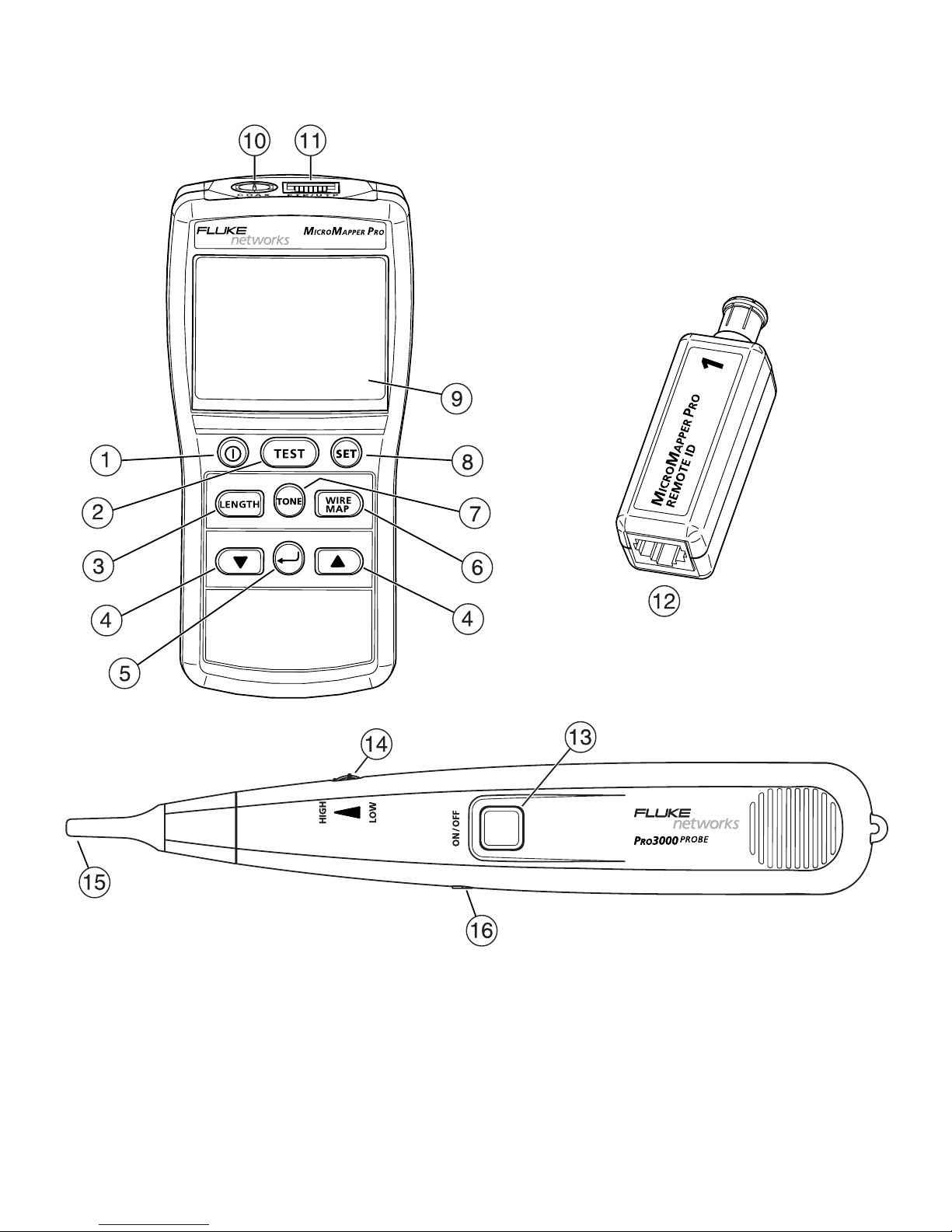
Features
etx01.eps

A
Power key.
B
Test key. Tests wire map, measures length, and gives a pass result or
shows faults.
C
Length key. Measures the cable length.
D
Scrolls through a list or displays.
E
Enter key. Selects the setting shown on the display.
F
Wire map key. Tests the wire map.
G
Tone key. Activates the toner.
H
Set key. Accesses setup selections.
I
LCD display.
J
F-connector for connecting to coaxial cables.
K
8-pin modular jack (RJ45) for connecting to UTP and FTP twisted pair
cables.
L
Remote identifier with F-connector and 8-pin modular jack (RJ45).
M
Power key on the optional PRO3000 tone probe.
N
Volume control.
O
Probe tip (not installed). To install the tip, insert it into the hole and turn
it clockwise a quarter turn until it stops.
P
Jack for optional earphone.

Battery Installation and Status
WWarningX
To avoid possible electric shock or personal injury:
•
Turn off the tester and disconnect all cables before installing the
batteries.
•
Use only the correct type of batteries, properly installed in the
case, to power the tester and probe.
Installing Batteries in the Tester
1
Remove the battery door screw under the bail on the back of the tester.
2
Install the 6 AAA alkaline batteries, noting the polarity shown in the
battery compartment.
3
Replace the battery door and secure it with the screw.
The tester’s batteries last for about 100 hours of typical use. Replace the
batteries when the low battery indicator ( ) appears.
Installing Batteries in the Optional PRO3000 Probe
1
Remove the middle screw on the back of the probe.
2
Remove the battery door.
3
Connect the 9 V alkaline battery and place it in the battery compartment,
taking care not to pinch the battery wires.
Replace the probe’s batteries when the probe’s volume weakens or the
probe stops working.

Changing the Length Units
1
Turn off the tester.
2
Hold down L; then hold down Ountil the display shows LEn Unit
(length unit).
3
Press Dor Cto select a length unit (mor ft).
4
Press Ato save the setting.
Setting Up the Tester
Note
You cannot turn off the tester in setup mode.
To change items in the setup menu (listed below), press S; then do the
following:
•
To change an item, press Dor C; then press Ato save your selection.
•
To scroll past an item without changing it, press A.
•
To exit setup mode, press S. The tester shows SEt PASS (setup pass) to
indicate the setup changes were made successfully. Press T, L, or
Wto run a test.
Cable Types
The selected cable type is displayed briefly when you run a test. For twisted
pair cable, the wire size is also shown.
•
CoA CAbLE: coaxial cable
r9-6: RG-6 coaxial cable, 75 Ω
r9-6USEr: RG-6 coaxial cable, 75 Ω, with a user-defined length calibration
parameter
r9-58: RG-58 coaxial cable, 50 Ω

r9-58USEr: RG-58 coaxial cable, 50 Ω, with a user-defined length
calibration parameter
•
FtP CAbLE: shielded twisted pair cable
•
UtP CAbLE: unshielded twisted pair cable
CAt5: Category 5 cable
CAt5-USEr: Category 5 cable, with a user-defined length calibration
parameter. Shows as CAt5-UA-<wire size> when you run a test.
Wire Sizes
A-28, A-26, A-24, A-22
Calibration Mode
•
CAL yES (calibration: yes): Enter length calibration mode. See
“Calibrating Length Measurements”.
•
CAL no (calibration: no): Do not enter length calibration mode.
Beeper
•
bEEP yES: (beeper: yes) Beeper is on.
•
bEEP no: (beeper: no) Beeper is off.
Testing Cables
The cable test checks for wiring faults based on the wire map stored for the
selected cable type and measures the cable length.
A remote identifier is not required for the cable test; however, opens at the
far end and miswires are not detected without a remote identifier.

To test a cable:
1
Select the cable type in setup.
2
Connect the cable to the tester. The tester shows no CAbLE (no cable)
when a cable is not connected.
3
Connect a remote identifier to the far end of the cable (optional).
4
Press T.
5
Wire numbers with a fault flash on the display. The EF icons appear if
information is available for additional faults. Use Dor Cto see the
other faults.
Tables 1, 2, and 3 show examples of cable test results.
Table 1. Test Results for Good Cable
Pass (PASS) results for unshielded, twisted pair
cable.
Remote ID #1 detected.
Pass results for unshielded, twisted pair cable.
No remote ID detected.
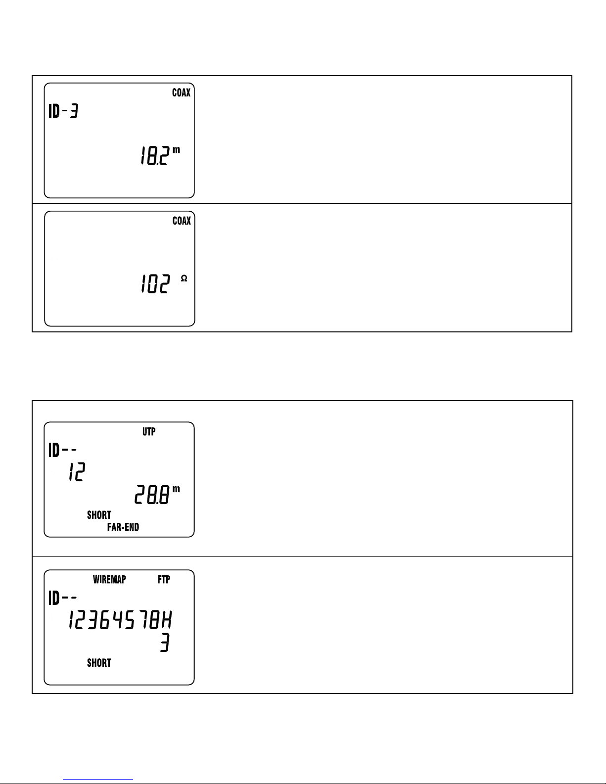
Results for coaxial cable.
Remote ID #3 detected.
Results for terminated coaxial cable. The tester
shows the total resistance of the cable and
terminator. Length cannot be measured on
terminated cable.
Table 2. Fault Results: Remote Identifier Optional
Short between wires 1 and 2.
The display shows the shorted wires and whether
the short is at the near end (NEAR-END) or far end
(FAR-END) of the cable.
For a short greater than 0 Ω, the displayed length
is greater than the actual distance to the short.
Short to the shield. For shielded cable (FTP) the
shield is shown as H.
The display shows the wire shorted to the shield
(wire 3 in this example).
-continued-
Table 1. Test Results for Good Cable (continued)
Table of contents
Other Fluke Cable Tester manuals

Fluke
Fluke MicroScanner Series User manual

Fluke
Fluke FI-3000 FiberInspector Pro User manual

Fluke
Fluke MicroScanner Series User manual

Fluke
Fluke IT200 User manual

Fluke
Fluke DSP-100 User manual

Fluke
Fluke LinkRunner Duo User manual

Fluke
Fluke LinkRunner Duo User manual

Fluke
Fluke TS 100 PRO User manual

Fluke
Fluke MicroMapper User manual

Fluke
Fluke LinkIQ User manual


