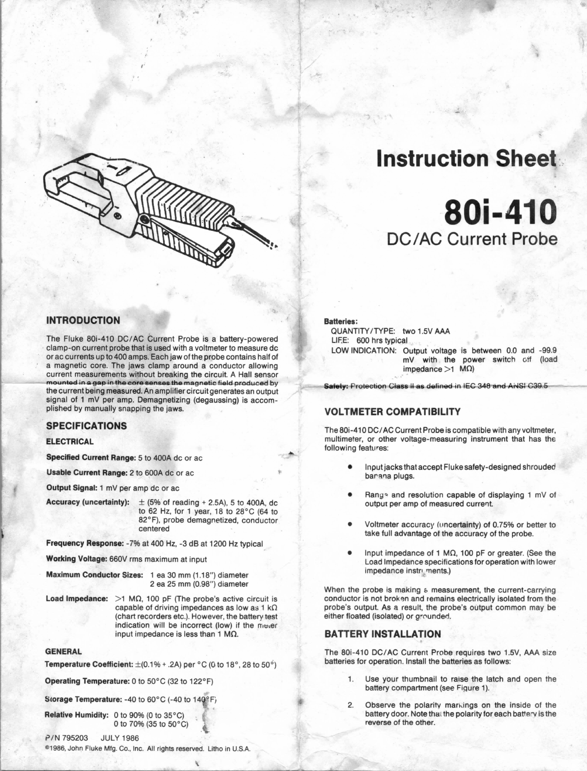
3. Install the batteries
so
that the polarity markings
on
the
batteries match the markings
on
the battery door.
4.
Snap the battery door shut.
NOTE
If
both batteries are not installed with the correct
polarity, thebatterytestmayindicate thatthebatteries
are good, but the probe will not operate.
OPERATION
Battery Test
' \ I I
CT]
I/
\ \
{
-9~mv
} •
~
00.0mV
O.K.
~
~~
+
Figure 1.
Use the following procedure to test the batteries:
1.
Connectthe probe output leads to the voltmeter inputs:
black to COMMON or
r.
ow
,and red to
VetT
.
2.
Setthe voltmeterfunction to
de
millivolts
(de
mV==),
and
turn the voltmeter power
on.
3.
Select a range capable of displaying 170
mV
de.
4.
Verify that the power switch on the probe is in the
OFF
position.
5.
Observe the voltmeter reading.
If
the reading falls
between -100.0 and -170.0
mV,
the probe is ready for
use.
(New batteries should read approximately -150
mV.)
If the reading falls between
0.0
and -99.9
mV,
the
batteries should be replaced. If the voltmeter reading is
positive, either the test leads are reversed or the
batteries are installed incorrectly.
Demagnetizing
When the 80i-410
DC/
AC
Current Probe has been used for a
currentmeasurementand then removed from the conductor,asmall
amo_unt
of residual magnetism often remains
in
the core. This
residual magnetism will generate a de offset at the probe output.
In
otherwords, the voltmeter will show asmall de reading even though
there is no current passing through the jaws of the probe. The
residual magnetism should not cause a problem for ac current
measurement because the ac voltage function
in
most multimeters
is ac coupled; therefore, the de offsetwill not
be
displayed. However,
for de current measurements, the
de
offset caused by the residual
magnetism will contributeto reading errors. The residual magnetism
can
be
minimized
as
follows
(see
Figure
2):
1.
Use
the thumb and forefinger of one hand to grasp the
probe
in
the middle where the two screw heads are
exposed.
2. With your other hand, compress the handles together,
then release them suddenly. The jaws should come
together with a snapping action.
3.
Repeat the above procedure twice.
Figure 2.
NOTE
The
snapping action will not damage the jaws
if
the
mating surfaces are kept clean. ·
Alternate Demagnetizing Procedures
Ifaconductor carrying ac current is available, clampthe jawsofthe
probe around the conductor, wait a few seconds, then slowly
remove the probe.
If
a conductor carrying de current is available,
clampthe jawsofthe probe around the conductor.Then removethe
probe and clamp itaround the conductor again so that the current
flows through the jaws
in
the opposite direction.
Making Measureme·nts ·
Use the following procedure to make current measurements
(see
Figure
3):
~
~
..CC).Qll~~~)ioiba-.OU:~lt.J.i~~~~~~~:..&Apw.I~
~~~-
(black to COMMON or
LOW
and
red
to
VOLTS)
.
2.
Selectthe appropriateac orde function on thevoltmeter.
3.
Turn on the voltmeter and select a voltage range to
display the expected value
(1
mV
per
amp).
4.
Turn the probe ON/OFF switch located on the probe
handle to the
ON
position.
5.
Observe the voltmeter reading. If necessary, demag-
netize the probe.
6.
Clampthejawsofthe probe around the conductorto
be
measured.Position the probeso thattheconductoris
in
the center of the jaw opening for the most accurate
reading.
7.
Observe the voltmeter display. The reading
in
millivolts
is equivalent to the current
in
amps
(i.e.,
5
mV
=SA). A
positive polarity reading indicates thatthe de current is
flowi
ng
in
th
e direction of the arrow
on
the probe.
Figure 3.