Fluke 2063513 User manual

Model 16 English Instruction Sheet
Page
1
®
16
Multimeter with Temperature
Instruction Sheet
P
Read First: Safety Information
To ensure that the meter is used safely, follow these instructions:
•Do not use the meter if the meter or test leads appear damaged, or if
you suspect that the meter is not operating properly.
•Disconnect the live test lead before disconnecting the common test
lead.
•When using the probes, keep your fingers behind the finger guards on
the probes.
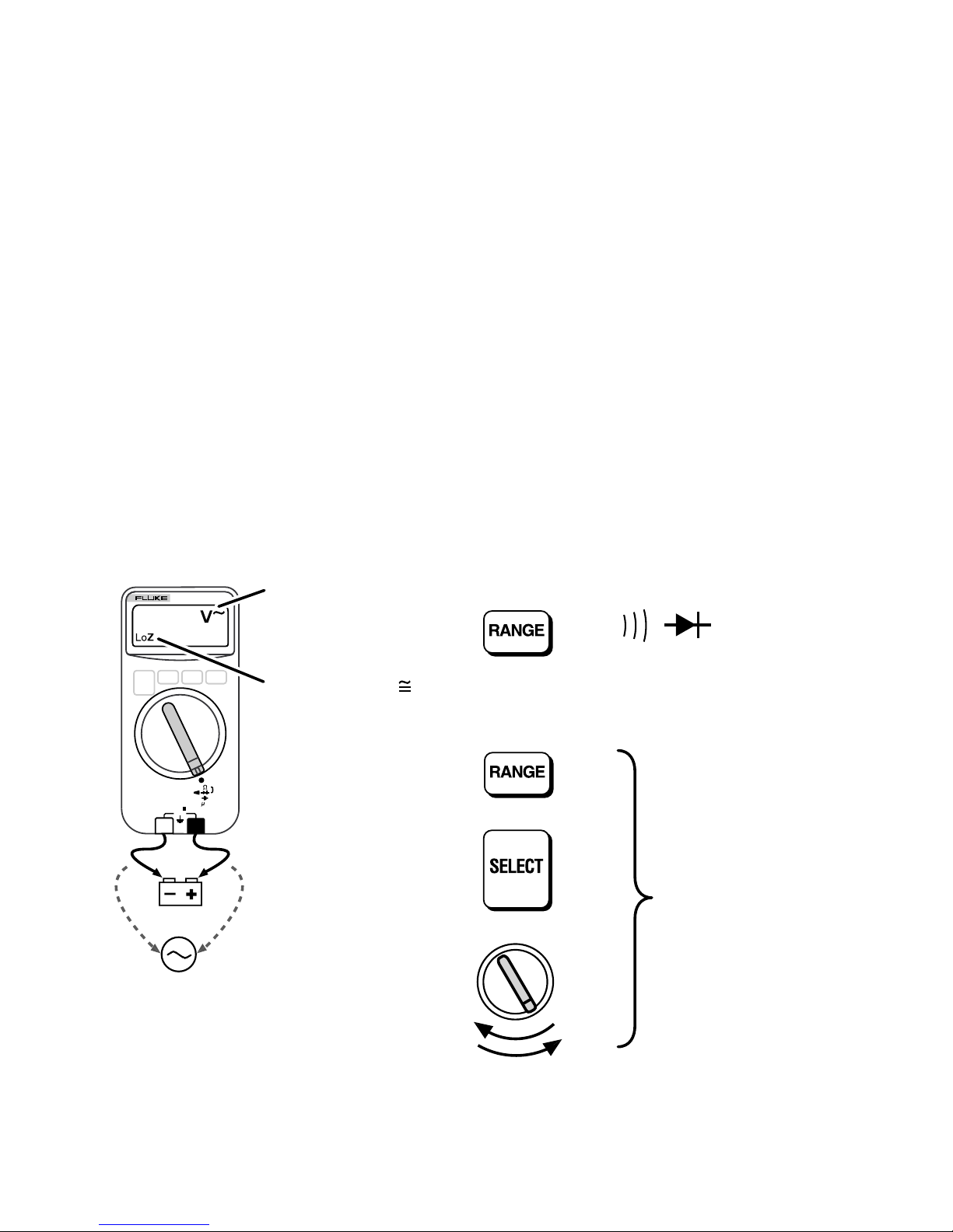
•Do not use the V•Check mode to measure voltages in circuits that
could be damaged by this mode's low input impedance
(≅2 kΩ).
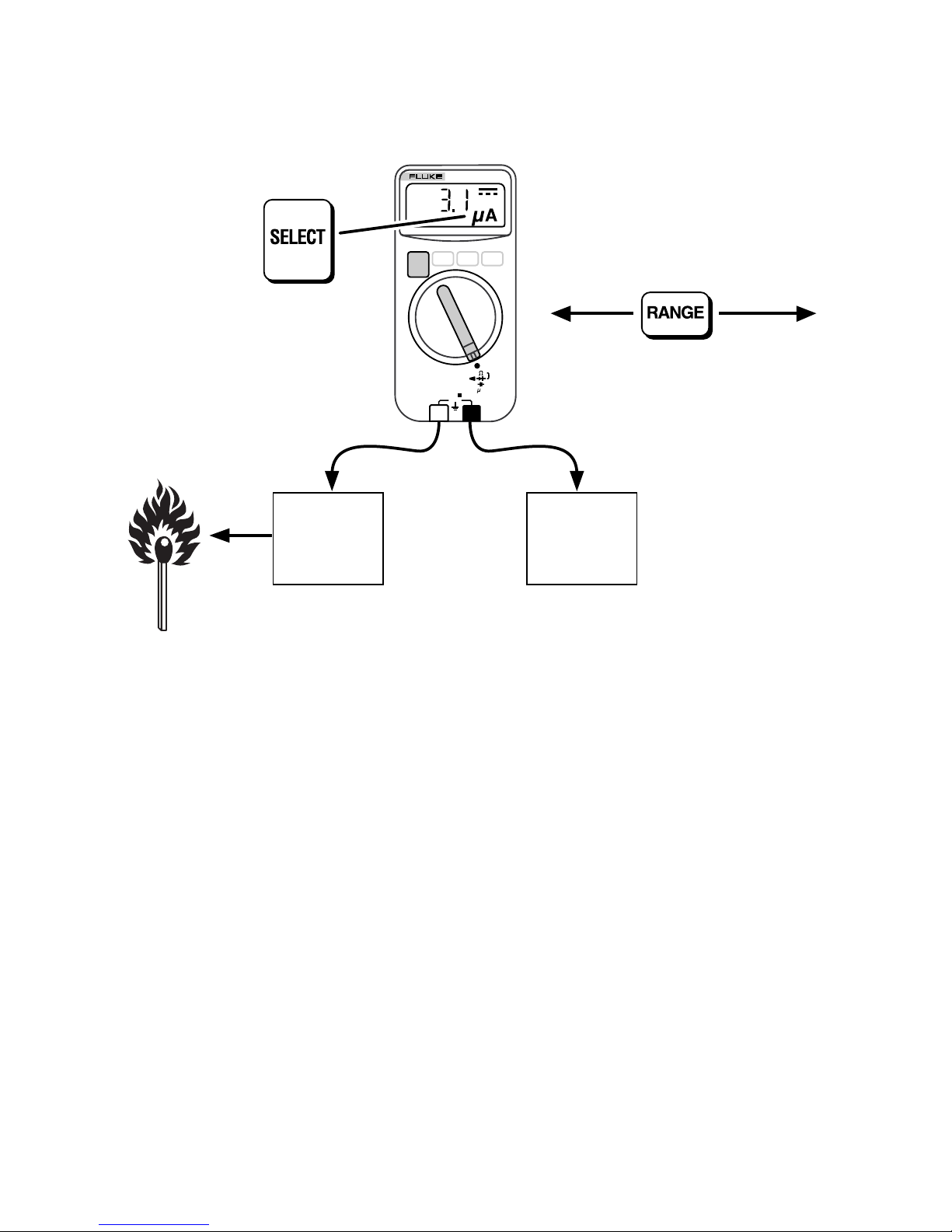
•Turn off power to the circuit under test before cutting, desoldering, or
breaking the circuit. Small amounts of current can be dangerous.
•Do not apply more than 600V rms between a meter terminal and earth
ground.
•Use caution when working with voltages above 60V dc or 30V ac rms.
Such voltages pose a shock hazard.
PN 2063513 December 2002 Rev.1, 9/04
2002,2004 Fluke Corporation. All rights reserved. Printed in China

Model 16 English Instruction Sheet
Page
2
Symbols
Press button.
Press button to switch between modes.
Double insulation.
Manual ranging mode.
ip14i.eps
Automatic Range Selection
The meter defaults to autoranging when you turn it on. The 4000 mV
range can be entered only with manual range selection.
Manual Range Selection
16
MULTIMETER
OFF
600V
COM
CAT
+
To return to autoranging, press for
2 seconds, or change the measurement
mode.
ip15i.eps
Battery Saver
If the meter is ON but inactive and not connected to voltage for more than
45 minutes, the display goes blank to preserve battery life. To resume
operation, press any button.
Battery Saveris disabled in MIN/MAX record mode.

Model 16 English Instruction Sheet
Page
3
AC and DC Voltage
Also refer to V•Check.
Volts AC Volts DC
Input Impedance ≅5 MΩInput Impedance ≅10 MΩ
50 Hz to 400 Hz
16
MULTIMETER
OFF
V
600V
COM
CAT
+
AC / DC
DCAC
4000 mV 4V 40V 400V 600V
16
MULTIMETER
OFF
V
600V
COM
CAT
+
AC / DC
ip01i.eps
Resistance and Continuity
eR
Turn off circuit power before testing. Also refer to V•Check.
Resistance Continuity
16
MULTIMETER
OFF
600V
COM
CAT
+
A
TEMPERATURE
V
¥
Check
16
MULTIMETER
OFF
600V
COM
CAT
+
A
TEMPERATURE
V
¥
Check
<25Ω
Mk
16
MULTIMETER
OFF
600V
COM
CAT
+
A
TEMPERATURE
V
¥
Check
Low Impedance
V¥Check
Short Open
ip02i.eps
Detects shorts and opens ≥250 µS.

Model 16 English Instruction Sheet
Page
4
W
V
•
Check
If a dc or ac voltage greater than about 4.5V is present across the inputs
when the meter is set to R, G, or e, the meter switches automatically
to dc or ac voltage mode (V•Check mode).
WWarning
Repetitive transients on a dc bus will cause V•Check to
select ac volts, even though a hazardous dc voltage may
be present. To avoid a misleading display and possible
electric shock, manually select the proper volts function
for measurements on these circuits.
When V•Check is activated, the meter has low input impedance (LoZ)
≅2 kΩ. This load can alter the voltages in electronic control circuits. Do
not use V•Check to measure voltage in circuits that could be damaged by
a 2 kΩload.
Hint: V•Check can be effectively used to eliminate “ghost” voltages.
16
MULTIMETER
OFF
600V
COM
CAT
+
A
TEMPERATURE
V
•
Check
or
If AC detected
If DC detected
Meter puts 2 kΩ
load on circuit.
Disable and re-enable V•Check
For , and Ω,
Disables V•Check and
locks meter in selected
mode.
2 sec
or
or
Re-enables
V•Check
ip09i.eps

Model 16 English Instruction Sheet
Page
5
Temperature
80BK
Integrated
Temperature
Probe (Type K)
Vent
or
Pipe
CF
16
MULTIMETER
OFF
600V
COM
CAT
+
A
TEMPERATURE
V
•
Check
ip19f.eps
Note correct connector polarity.
To meet stated accuracy, the 80BK temperature adapter must be at the
same temperature as the meter.
WWarning
To avoid possible electric shock, DO NOT apply
thermocouple tip to any conductor that is greater than
30V AC, 42.4V pk, or 60V DC to earth.

Model 16 English Instruction Sheet
Page
6
Capacitance
E
Turn off circuit power; then disconnect and discharge the capacitor before
measuring capacitance.
+
If the capacitor requires more
discharging, diSC is displayed
while the capacitor discharges.
1 µF 10 µF 100 µF 10,000 µF
16
MULTIMETER
OFF
600V
COM
CAT
+
A
TEMPERATURE
V
•
Check
ip05i.eps
Note correct probe polarity for polarized capacitors.

Model 16 English Instruction Sheet
Page
7
Microamps
µA
Range 0 to 200 µA
16
MULTIMETER
OFF
600V
COM
CAT
+
A
TEMPERATURE
V
•
Check
Flame
sensor
probe
Control
module
µA AC µA DC
ip20i.eps
Example: Flame rectification circuit.
To measure flame rectification circuits:
1. Turn function switch to far right position.
2. Push select button 3 times to select µA.
3. Connect meter between flame sensor probe and control module.
4. Turn heating unit on and record µA measurement.

Model 16 English Instruction Sheet
Page
8
Diode Test
G
Turn off circuit power before testing. For best results diodes
should be measured out of circuit.
Also refer to V•Check.
Good Diode
16
MULTIMETER
OFF
600V
COM
CAT
+
A
TEMPERATURE
V
•
Check
16
MULTIMETER
OFF
600V
COM
CAT
+
A
TEMPERATURE
V
•
Check
Typical voltage
for silicon diode
Single beep
Low Impedance
V•Check
ip03i.eps
Forward Bias Reverse Bias
Bad Diode
16
MULTIMETER
OFF
600V
COM
CAT
+
A
TEMPERATURE
V
•
Check
or
16
MULTIMETER
OFF
600V
COM
CAT
+
A
TEMPERATURE
V
•
Check
ip04i.eps
Shorted Open

Model 16 English Instruction Sheet
Page
9
MIN MAX
µF
(Records the lowest and highest measurements)
V•Check, autoranging, and Battery Saverare disabled. Put the meter
in the proper range before entering MIN MAX.
When the reading changes more than about 50 digits, the meter gives a
short beep. When a new minimum or maximum is recorded, the meter
gives a long beep.
Present Reading with
Input Change Alert Maximum Reading
Minimum Reading To Exit
Enter
MIN MAX
2 sec
TM
ip10i.eps

Model 16 English Instruction Sheet
Page
10
MIN MAX with Elapsed Time
µF
Records the hours and minutes between when MIN MAX was entered
and the last high and low was recorded. OL is displayed for times longer
than 99:59.
To enable the MIN MAX timer, hold down Mwhile turning the rotary
switch from OFF to either measurement mode.
Enter MIN MAX. View
Present Reading Maximum Reading Maximum Reading
Elapsed Time
Minimum Reading
Elapsed Time Minimum Reading Exit MIN MAX
2 sec
ip11i.eps

Model 16 English Instruction Sheet
Page
11
Disabling the Beeper
To disable the beeper for all modes, hold down rfor 2 seconds while
turning the meter on.
Continuity Capture
To set up the meter to capture intermittent shorts and opens, turn the
switch to GR, connect the leads to the circuit; then press M.
ip12i.eps
Captures transitions longer than 250 µs (1/4000th of a second).
Transitions after the first transition cause the meter to beep, but the
display does not change.
To reset the display to the current condition, press M.
To exit, press Mfor 2 seconds, or change the measurement mode.

Model 16 English Instruction Sheet
Page
12
Maintenance
Clean the case with a damp cloth and detergent. Do not use abrasives or
solvents.
Battery Replacement
Remove the test leads before disassembling the case.
+
COM
600V
+
ip13i.eps
Replacement Parts
Fluke TL-75 (Double-insulated leads) PN 855705
80BK (Integrated Temperature Probe) PN 1273124
Service and Parts
This meter should be serviced only by a qualified service technician. To
locate an authorized service center, call:
USA: 1-888-99-FLUKE (1-888-993-5853)
Canada: 1-800-36-FLUKE (1-800-363-5853)
Europe: +31 402-675-200
Japan: +81-3-3434-0181
Singapore: +65-738-5655
Anywhere in the world: +1-425-446-5500
Or, visit Fluke's Web site at www.fluke.com.

Model 16 English Instruction Sheet
Page
13
Specifications
Accuracy is specified for a period of one year after calibration, at 18°C to
28°C (64°F to 82°F) with relative humidity to 90%. AC conversions are
ac-coupled, average responding, and calibrated to the rms value of a sine
wave input. Accuracy specifications are given as follows:
±([% of reading] + [number of least significant digits])
Function Range Resolution Accuracy
Temperature -10°C to 400°C
14°F to 752°F
0.1°C or
0.2°F
±(1.0% + 0.8°C)
typical
±(1.0% + 1.5°F) typical
(Type K Thermocouple) -40°C to -10°C
-40°F to 14°F
0.1°C or
0.2°F
±(5.0% + 1.5°C)
typical
±(5.0% + 3.3°F) typical
Error does not include Type K Thermocouple errors.
Function Range Resolution Accuracy
f
(50 to 400 Hz)
4000 mV1
4.000V
40.00V
400.0V
600V
1 mV
0.001V
00.01V
000.1V
1V
±(1.9% + 3)
±(1.9% + 3)
±(1.9% + 3)
±(1.9% + 3)
±(1.9% + 3)
E
4000 mV1
4.000V
40.00V
400.0V
600V
1 mV
0.001V
00.01V
000.1V
1V
±(0.9% + 2)
±(0.9% + 2)
±(0.9% + 1)
±(0.9% + 1)
±(0.9% + 1)
Ω
400.0Ω
4.000 kΩ
40.00 kΩ
400.0 kΩ
4.000 MΩ
40.00 MΩ
0.1Ω
0.001 kΩ
0.01 kΩ
0.1 kΩ
0.001 MΩ
0.01 MΩ
±(0.9% + 2)
±(0.9% + 1)
±(0.9% + 1)
±(0.9% + 1)
±(0.9% + 1)
±(1.5% + 3)
|
1.000 µF
10.00 µF
100.0 µF
10000 µF
0.001 µF
0.01 µF
0.1 µF
1 µF
±(1.9% + 2)
±(1.9% + 2)
±(1.9% + 2)
≤1000 µF ±(1.9% + 2)
>1000 µF ±(10% + 90) typical
ML 2.000V 0.001V ±(1.9% + 2)2
1.The 4000 mV range can be entered only in manual range mode. Use the
4000 mV range with accessories.
2.The beeper is guaranteed to come on at <25Ωand turn off at >250Ω. The
meter detects opens or shorts ≥250 µs.

Model 16 English Instruction Sheet
Page
14
Function Range Resolution Accuracy Burden Voltage
N
(50 Hz to 400 Hz) 0 to 200 µA0.1µA ±(2% + 3 counts) <5 mV/µA
M0 to 200 µA0.1µA ±(1% + 2 counts) <5 mV/µA
Function Overload
Protection1Input Impedance (Nominal)
f600V rms >5 MΩ<100 pF
V•Check and LoZ= >2 kΩ<200 pF (ac coupled)2
E600V rms >10MΩ<100 pF
V•Check and LoZ= >2 kΩ<200 pF2
Common Mode Rejection
Ratio (1 kΩUnbalanced) Normal Mode Rejection
f600V rms >60 dB at dc 50 or 60 Hz
E600V rms >100 dB at dc, 50 or 60 Hz >50 dB at 50 Hz or 60 Hz
Open Circuit Test Voltage Full Scale Voltage
To 4.0 MΩ40 MΩ
J 600V rms <1.5V dc <450 mV dc <1.5V dc
L 600V rms 2.4-3.0V dc 2.400V dc
Short Circuit Current
J 600V rms <500 µA
L 600V rms 0.95 mA (typical)
1. 3 x 10⁶V Hz maximum
2. ≅2 kΩinput impedance up to 50V. Impedance increases with input voltage to
>300 kΩat 600V.
MIN MAX Recording Accuracy and Response Time
Specified accuracy of the measurement function ±12 digits in dc for changes
>200 ms in duration (±40 digits in ac). Typical 100 ms response to 80%.
Example 1: This would mean ±1.2°when recording temperature.
Example 2: This would mean ±1.2 µA when recording µA or ±12A if used with a
dc amp probe (with a mV input).

Model 16 English Instruction Sheet
Page
15
MIN MAX Recording with Elapsed Time
Elapsed Time Resolution Accuracy
0 to 100 hours (99:59) 1 minute 0.3% typical
Maximum Voltage
Between any Terminal
and Earth Ground:
600V rms
Display: 3 3/4-digits, 4000 counts, updates 4/sec
Operating Temperature: -10°C to 50°C (14°F to 122°F)
Storage Temperature: -30°C to 60°C (-22°F to 140°F)
indefinitely (to -40°C (-40°F) for 100 hrs)
Temperature
Coefficient:
(.1 x specified accuracy)/°C (<18°C or
>28°C)
Relative Humidity: 0% to 90% (-10°C to 35°C; 14°F to 95°F)
0% to 70% (35°C to 50°C; 95°F to 122°F)
Battery Type: 9V, NEDA 1604 or IEC 6F22
Battery Life: 650 continuous hours with alkaline
450 continuous hours with carbon-zinc
Shock: 1 meter drop 6 sides.
Vibration: Class II vibration MIL-PRF-28800F
Size (H x W x L): 3.46 cm x 7.05 cm x 14.23 cm
(1.35 in x 2.75 in x 5.55 in)
Weight: 286g (10 oz)
Safety: Designed to Protection Class II
requirement of UL3111, ANSI/ISA-S82,
CSA C22.2 No 231, and VDE 0411, and
IEC 1010 overvoltage Category III (CAT
III, 600 Volts).
EMI Regulations: Complies with FCC Part 15, Class B, and
VDE 0871B. Trademark of TÜV Product
Services. Complies with EN 61010-1:
1993.
Certifications: P$
TUV, UL and VDE

Model 16 English Instruction Sheet
Page
16
LIMITED WARRANTY & LIMITATION OF LIABILITY
Each Fluke product is warranted to be free from defects in material and workmanship under
normal use and service. The warranty period is three years and begins on the date of shipment.
Parts, product repairs and services are warranted for 90 days. This warranty extends only to the
original buyer or end-user customer of a Fluke authorized reseller, and does not apply to fuses,
disposable batteries or to any product which, in Fluke's opinion, has been misused, altered,
neglected or damaged by accident or abnormal conditions of operation or handling. Fluke
warrants that software will operate substantially in accordance with its functional specifications for
90 days and that it has been properly recorded on non-defective media. Fluke does not warrant
that software will be error free or operate without interruption.
Fluke authorized resellers shall extend this warranty on new and unused products to end-user
customers only but have no authority to extend a greater or different warranty on behalf of Fluke.
Warranty support is available if product is purchased through a Fluke authorized sales outlet or
Buyer has paid the applicable international price. Fluke reserves the right to invoice Buyer for
importation costs of repair/replacement parts when product purchased in one country is submitted
for repair in another country.
Fluke's warranty obligation is limited, at Fluke's option, to refund of the purchase price, free of
charge repair, or replacement of a defective product which is returned to a Fluke authorized
service center within the warranty period.
To obtain warranty service, contact your nearest Fluke authorized service center or send the
product, with a description of the difficulty, postage and insurance prepaid (FOB Destination), to
the nearest Fluke authorized service center. Fluke assumes no risk for damage in transit.
Following warranty repair, the product will be returned to Buyer, transportation prepaid (FOB
Destination). If Fluke determines that the failure was caused by misuse, alteration, accident or
abnormal condition of operation or handling, Fluke will provide an estimate of repair costs and
obtain authorization before commencing the work. Following repair, the product will be returned to
the Buyer transportation prepaid and the Buyer will be billed for the repair and return
transportation charges (FOB Shipping Point).
THIS WARRANTY IS BUYER'S SOLE AND EXCLUSIVE REMEDY AND IS IN LIEU OF ALL
OTHER WARRANTIES, EXPRESS OR IMPLIED, INCLUDING BUT NOT LIMITED TO ANY
IMPLIED WARRANTY OF MERCHANTABILITY OR FITNESS FOR A PARTICULAR PURPOSE.
FLUKE SHALL NOT BE LIABLE FOR ANY SPECIAL, INDIRECT, INCIDENTAL OR
CONSEQUENTIAL DAMAGES OR LOSSES, INCLUDING LOSS OF DATA, WHETHER
ARISING FROM BREACH OF WARRANTY OR BASED ON CONTRACT, TORT, RELIANCE OR
ANY OTHER THEORY.
Since some countries or states do not allow limitation of the term of an implied warranty, or
exclusion or limitation of incidental or consequential damages, the limitations and exclusions of
this warranty may not apply to every buyer. If any provision of this Warranty is held invalid or
unenforceable by a court of competent jurisdiction, such holding will not affect the validity or
enforceability of any other provision.
Fluke Corporation Fluke Europe B.V.
P.O. Box 9090 P.O. Box 1186
Everett WA 5602 B.D. Eindhoven
98206-9090 The Netherlands
5/94
This manual suits for next models
2
Table of contents
Other Fluke Multimeter manuals

Fluke
Fluke LinkRunner Duo User manual

Fluke
Fluke 1587 FC User manual

Fluke
Fluke 1508 User manual

Fluke
Fluke 87 TRUE RMS MULTIMETER User manual

Fluke
Fluke 8505A User manual

Fluke
Fluke 8808A User manual

Fluke
Fluke 789 Use and care manual

Fluke
Fluke 28IIEX User manual

Fluke
Fluke 8840A User manual

Fluke
Fluke 88 V User manual

Fluke
Fluke 8022A User manual

Fluke
Fluke 8845A User manual

Fluke
Fluke 87 III Series Operating and installation instructions

Fluke
Fluke 1630 Instruction manual

Fluke
Fluke 867B User manual

Fluke
Fluke a3002 FC Use and care manual

Fluke
Fluke 80 Series V User manual

Fluke
Fluke 113 Use and care manual

Fluke
Fluke 789 Original instructions

Fluke
Fluke 175 User manual