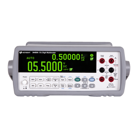
Fluke 28 II Ex Installation instructions

1
Safety instructions
Instructions de sécurité · Sicherheitshinweise
Fluke 28 II EX

2

3
Contents
1. Contents................................................................................................................................................................................... 1
2. Application.............................................................................................................................................................................. 4
3. Safety information............................................................................................................................................................... 4
4. Errors and load restrictions........................................................................................................................................... 5
5. Ex-Certification Data........................................................................................................................................................ 5
5.1 Table with type-approved batteries.......................................................................................................................... 7
5.2 Table with approved accessories................................................................................................................................ 7
5.3 Table - Replacement Parts............................................................................................................................................. 7
6. Maintenance........................................................................................................................................................................... 8
6.1 General Maintenance........................................................................................................................................................ 8
Note:
Go to www.ecom-ex.com to download the current EU declaration of conformity and Ex
certificate for this product.You can also order them from Fluke.

4
2.Application
The 28 II EX Digital Multimeter (the Product) is a compact easy to operate measurement tool
for electrical and electronic circuits.The Product is designed for operation in potentially explosive
areas of Zone 1, 2 and M1, as specified in Directive 1999/92/EC and 2014/34/EU (ATEX).There
can be dangerous consequences if you do not follow these instructions.
Read the entire Safety Instructions before you use the Product.
3. Safety information
If there is a question (because of translation and/or printing errors), refer to the English Safety
Instructions.These instructions contain information and safety regulations that must be followed
to ensure safe, reliable operation of the Product in hazardous areas under the described con-
ditions. Failure to follow the information and instructions can have dangerous consequences, or
may contravene applicable legislation. Please also read through the users manual before you start
to use the Product.To ensure safe operation of the Product, obey all instructions and warnings
contained in these instructions.
Warning
To prevent electric shock or personal injury while in Ex-HAZARDOUS areas,
follow these guidelines:
- Do not open the Product while in an Ex-hazardous area.
- Change the Product’s batteries only outside Ex-hazardous areas.
- Do not take spare batteries into Ex-hazardous areas.
- Use only type-approved batteries in the Product. See item 5.1 for a list of approved batteries.
- Different temperature ranges forTamb are fixed by the type approved batteries - see item 5.1.
- Do not replace fuses while in an Ex-hazardous area.
- Use only fuses approved for Ex-hazardous areas in this Product.
See item 5.3: Table - Replacements Parts for a list of approved fuses.
- Use the Product only when the specified connection values are met.
- After you use the Product on a non-i.s. protected circuit, wait 3 minutes before you take the
Product into an Ex-hazardous area.
-The Product must be completely and securely fitted in the red holster while it is in an Ex-hazar-
dous area.
- Use only approved accessories with this Product in Ex-hazardous areas.
- Do not use the Product in aggressive acidic or alkaline solutions.
- For applications requiring Group I equipment, the permanent contact of the Fluke 28 II EX
with oils, hydraulic fluids or greases is to avoid.A fixed installation of the Fluke 28 II EX is not
permitted.
- Do not use the Product in Zone 0 or 20, 21 and 22. Measurements on intrinsically safe
connections that go into these zones are permitted, if the connection values are met.
To prevent personal injury in mining hazardous areas:
- Avoid extreme mechanical burdens.The Product can withstand impacts with an energy of seven
joules at -20°C.
- Do not allow the Product to come in permanent contact with oils, hydraulic fluid, or grease.
- Do not install the Product in a fixed installation.

5
4. Errors and load restrictions
If there is any question that the safety or integrity of this Product is compromised, remove it from
operation and the Ex-hazardous areas immediately. Also, do whatever is necessary to prevent
Product operation by others until the Product is examined by an ecom certified technician.
It is recommended that you send the Product to the manufacturer to be examined.
Because the safety and reliability of the Product can be at risk, do not operate the Product if:
-Visible damage is found in the housing of the Product.
-The Product has had an excessive load put on it for which it is not designed.
-The Product was not stored correctly.
-The Product has sustained damage in transit.
- Illegible inscriptions or lettering shows on the Product.
- A Product malfunction occurs.
- Obvious measurement inaccuracies occur.
- Measurements/simulations are no longer possible with the Product.
- Permitted tolerances or threshold values were exceeded.
5. Ex-Certification Data
EU-Type Examination Certificate No.: PTB 11 ATEX 2028 X
Ex-marking: II 2G Ex ia IIC T4 Gb
I M1 Ex ia I Ma
IECEx Certificate of Conformity no.: IECEx PTB 11.0080X
Ex-marking: Ex ia IICT4 Gb
Ex ia I Ma
For connections to intrinsically-safe circuits, (Ex ia IIC resp. Ex ia I) observe these Product
connections:
V/Ohm - COM
Uo = 9.54V
Io = 3.7 mA
Po = negligible low
Ri = 2.47KΩ(linear characteristic)
Li = negligible low
Ci = negligible low
The max. permissible external inductance Lo and capacitance Co are listed below.
For this the simultaneous occurrence of capacitance and inductance are taken into account.
Lo/mH 1000 100 2 0.5 0.1 0.01
Co/μF 0 0.61 1 1.4 2.1 3.6

6
or
For connection to a certified intrinsically safe circuit.
Ui≤65V
The rules of interconnection of intrinsically safe circuits have to be taken into account.
mA/μA-COM
Uo = 1.95V
Io = 9.7 μA
Po = negligible low
Li = negligible low
Ci = negligible low
Ii = internally limited by 440mA fuse
The max. permissible external inductance Lo and capacitance Co are listed below. For this the
simultaneous occurrence of capacitance and inductance are taken into account.
Lo/mH 1000 100 5 1 0.5 0.005
Co/μF 0 14 19 25 30 1000
or
For connection to a certified intrinsically safe circuit.
Ui≤65V
The rules for interconnection of intrinsically safe circuits have to be taken into account.
A-COM
Uo = 0V
Io = 0 mA
Po = 0 mW
Li = negligibly low
Ci = negligibly low
For connection to a certified intrinsically safe circuit.
Ui≤65V
Ii ≤5 A
The rules for interconnection of intrinsically safe circuits have to be taken into account.
CE:
Operating temperature Different temperature ranges are fixed by the used types
of approved batteries - see item 5.1.
Storage temperature: -40°C... +60°C (without batteries)
Batteries / power supply:
3 AAA Alkaline batteries, NEDA 24A IEC LR03. FollowingTable shows the approved batteries for
this Product.

7
5.1 Table with type-approved batteries
ATEX
Manufacturer Type Tamb
1 Eveready Energizer No. E92 -15°C ≤Ta ≤+50°C
2Varta Max Tech No. 4703 -15°C ≤Ta ≤+50°C
3Varta Industrial Alcaline No. 4003 [1] -10°C ≤Ta ≤+50°C
4 Rayovac Alcaline AAA -15°C ≤Ta ≤+50°C
5 Panasonic Alcaline Power LR03 [2] -15°C ≤Ta ≤+45°C
6 Panasonic Pro Power LR03 [2] -15°C ≤Ta ≤+45°C
[1] Minimum operating temperature is -10 °C.
[2] Maximum operating temperature is +45 °C.
5.2 Table with approved accessories
Item
TL175 Silicone test lead set with probes
80BK-A BeadTemperature Probe
AC172 (or)
AC175
Alligator Clips
i400 AC Current Clamp
80PK-27 Temperature Probe
5.3 Table - Replacement Parts
Description Fluke Part or Model Number
Fuse, 11A, 1000V, FAST 803293
28 II EX Fuse Assembly 4016494
28 II EX Holster 4013542

8
6. Maintenance
Warning
To prevent electrical shock or personal injury, have the Product repaired by ecom Instruments
GmbH or an ecom authorized service center to keep Product certification.
6.1 General Maintenance
To clean the external surfaces of the Product, wipe the case with a damp cloth and mild
detergent.
Do not use abrasives or solvents.
Dirt or moisture in the terminals can cause incorrect measurements and can falsely set off the
Input Alert feature. Clean the terminals as follows:
1.Turn the Product off and remove all test leads.
2. Shake out dirt that can be in the terminals.
3. Soak a clean swab with mild detergent and water.
Move the swab around in each terminal. Dry each terminal with canned air to push the water
and detergent out of the terminals.

9
Table des matières
1. Table des matières.............................................................................................................................................................9
2. Application.............................................................................................................................................................................10
3. Informations de sécurité................................................................................................................................................10
4. Erreurs et restrictions de charge..............................................................................................................................11
5. Données de certification Ex .......................................................................................................................................11
5.1 Tableau des types de piles approuvés....................................................................................................................13
5.2 Tableau des accessoires approuvés.........................................................................................................................13
5.3 Tableau des pièces de rechange................................................................................................................................13
6. Maintenance..........................................................................................................................................................................14
6.1 Maintenance générale.....................................................................................................................................................14
Remarque :
Rendez-vous à l‘adresse suivante : www.ecom-ex.com pour télécharger la déclaration de confor-
mité UE et le certificat Ex pour ce produit.Vous pouvez également les commander auprès de
Fluke.

10
2.Application
Le multimètre numérique 28 II EX (le Produit) est un outil de mesure compact et facile à utiliser
pour les circuits électriques et électroniques. Le produit est conçu pour une utilisation dans les
zones potentiellement explosives des Zones 1, 2 et M1 conformément aux directives 1999/92/
CE et 2014/34/UE (ATEX). Le non-respect de ces instructions peut avoir des conséquences
dangereuses.Avant toute utilisation du produit, veuillez lire les instructions de sécurité dans leur
intégralité.
3. Informations de sécurité
En cas de doute (en raison d’erreurs de traduction et / ou d’impression), se reporter aux instruc-
tions de sécurité originales en anglais. Les présentes instructions contiennent des informations et
des règles de sécurité à observer afin de garantir un fonctionnement efficient et en toute sécu-
rité du produit dans les zones dangereuses en présence des conditions stipulées. Le non-respect
de ces informations et instructions peut avoir des conséquences dangereuses et représenter une
infraction à la loi applicable.Avant toute utilisation du produit, prière de lire l’intégralité du manuel
d’utilisation.Afin de garantir une utilisation en toute sécurité du produit, observer toutes les inst-
ructions et avertissements contenus dans les présentes instructions.
En cas de doute (en raison d‘erreurs de traduction et/ou d‘impression), consulter le Instructions
de sécurité rédigé en anglais.
Avertissement
Afin d‘éviter les chocs électriques ou blessures dans les zones EXPLOSIVES, respecter les
instructions suivantes :
- Ne pas ouvrir le Produit dans une zone explosive.
- Remplacer les piles du Produit uniquement en dehors des zones explosives.
- Ne pas apporter de piles de rechange dans les zones explosives.
- Utiliser dans le Produit uniquement des piles de type approuvé.Voir la section 5.1Tableau des
types de piles approuvés pour connaître la liste des piles approuvées.
- Différentes plages de températures ambiantes sont définies par les batteries homologuées –
voir élément 5.1.
- Ne pas remplacer les fusibles dans une zone explosive.
-Voir élément 5.3 : tableau des pièces de rechange pour une liste de fusibles agréés.
- Utiliser le Produit uniquement lorsque les valeurs de connexion spécifiées sont respectées.
- Après l‘utilisation du Produit sur un circuit sans sécurité intrinsèque, attendre 3 minutes avant de
transporter le Produit dans une zone explosive.
- Lorsqu‘il se trouve dans la zone explosive, le Produit doit être complètement et fermement
inséré dans l‘étui rouge.
- Utiliser avec ce Produit uniquement les accessoires approuvés pour les zones explosives.
- Pour les applications qui nécessitent un équipement du groupe I, éviter tout contact permanent
du Fluke 28 II EX avec les huiles, les fluides hydrauliques et les graisses.Toute installation fixe du
Fluke 28 II EX est interdite.
- Ne pas utiliser le produit dans les Zones 0 ou 20, 21 et 22. Les mesures sont autorisées sur
les connexions à sécurité intrinsèque qui entrent dans ces zones à condition de respecter les
puissances connectées.

11
Afin d’éviter les blessures dans les zones minières dangereuses :
- Éviter les charges mécaniques extrêmes. Le produit résiste aux impacts avec une énergie de
sept joules à -20 °C.
- Ne pas laisser le produit en contact permanent avec des huiles, des fluides hydrauliques ou des
graisses.
- Ne pas installer le produit dans une installation fixe.
4. Erreurs et restrictions de charge
En cas de doute sur la sécurité ou l‘intégrité de ce Produit, ne plus l‘utiliser et le retirer immédi-
atement des zone explosives. Prendre toutes les mesures nécessaires pour empêcher l‘utilisation
du Produit par des tiers tant que celui-ci n‘a pas été examiné par un technicien certifié ecom.
Il est recommandé d‘envoyer le Produit au fabricant pour examen.
La sécurité et la fiabilité du Produit pouvant être compromises, ne pas utiliser le Produit si :
- Des dommages externes sont visibles sur le boîtier du Produit.
- Le Produit a subi une charge excessive pour laquelle il n‘a pas été conçu.
- Le Produit n‘a pas été stocké correctement.
- Le Produit a été endommagé lors du transport.
- Les inscriptions ou lettres sur le Produit sont illisibles.
- Le Produit présente un dysfonctionnement.
- De flagrantes erreurs de précision des mesures se produisent.
- Le Produit n‘est plus capable d‘effectuer des mesures/simulations.
- Les tolérances ou valeurs limites autorisées ont été dépassées.
5. Données de certification Ex
Certificat d’examen de type UE n° : PTB 11 ATEX 2028 X
Désignation Ex : II 2G Ex ia IICT4 Gb
I M1 Ex ia I Ma
Certificat de conformité IECEx n° : IECEx PTB 11.0080X
Désignation Ex : Ex ia IICT4 Gb
Ex ia I Ma
Pour connecter le Produit à des circuits à sécurité intrinsèque, (Ex ia IIC resp. Ex ia I) respectez
les valeurs suivantes :
V/ohm – COM
Uo = 9,54V
Io = 3,7 mA
Po = négligeable car faible
Ri = 2,47 KΩ(caractéristiques linéaires)
Li = négligeable car faible
Ci = négligeable car faible
L’inductance externe Lo et la capacité Co max. admissibles sont indiquées ci-après. À cet effet,
observer l’occurrence simultanée de la capacité et de l’inductance.

12
Lo/mH 1000 100 2 0,5 0,1 0,01
Co/μF 0 0.61 1 1,4 2,1 3,6
ou
Pour la connexion à un circuit à sécurité intrinsèque certifiée. Ui≤65 V
Observer les règles d’interconnexion des circuits à sécurité intrinsèque.
mA/μA-COM
Uo = 1,95V
Io = 9,7 μA
Po = négligeable car faible
Li = négligeable car faible
Ci = négligeable car faible
Ii = limité en interne par un fusible de 440 mA
L’inductance externe Lo et la capacité Co max. admissibles sont indiquées ci-après. À cet effet,
observer l’occurrence simultanée de la capacité et de l’inductance.
Lo/mH 1000 100 5 1 0,5 0,005
Co/μF 0 14 19 25 30 1000
ou
Pour la connexion à un circuit à sécurité intrinsèque certifiée.
U≤65V
Observer les règles d’interconnexion des circuits à sécurité intrinsèque.
A-COM
Uo = 0V
Io = 0 mA
Po = 0 mW
Li = négligeable car faible
Ci = négligeable car faible
Pour la connexion à un circuit à sécurité intrinsèque certifiée.
Ui≤65V
Ii ≤5 A
Observer les règles d’interconnexion des circuits à sécurité intrinsèque.
CE :
Température d‘utilisation Différentes plages de températures sont définies par les piles
homologuées employées – voir élément 5.1.
Température de stockage : -40 °C ... +60 °C (sans piles)
Piles / alimentation : 3 piles alcalines AAA, NEDA 24A IEC LR03. Le tableau suivant présente les

13
piles approuvées pour ce Produit.
5.1 Tableau des types de piles approuvés
ATEX
Fabricant Type Tamb
1 Eveready Energizer No. E92 -15°C ≤Ta ≤+50°C
2Varta Max Tech No. 4703 -15°C ≤Ta ≤+50°C
3Varta Industrial Alcaline No. 4003 [1] -10°C ≤Ta ≤+50°C
4 Rayovac Alcaline AAA -15°C ≤Ta ≤+50°C
5 Panasonic Alcaline Power LR03 [2] -15°C ≤Ta ≤+45°C
6 Panasonic Pro Power LR03 [2] -15°C ≤Ta ≤+45°C
[1] La température minimale d‘utilisation est -10 °C.
[2] La température maximale d‘utilisation est +45 °C.
5.2 Tableau des accessoires approuvés
Article
TL175 Jeu de fils de test en silicone avec sondes
80BK-A Sonde de température à perle
AC172 (ou)
AC175
Pinces crocodile
i400 AC Collier courant
80PK-27 Sonde de température
5.3 Tableau des pièces de rechange
Description Numéro de pièce ou de référence Fluke
Fusible instantané 11A; 1000 V 803293
Ensemble de fusibles 28 II EX 4016494
Etui 28 II EX 4013542

14
6. Maintenance
Avertissement
Afin d‘éviter les chocs électriques ou blessures, faire réparer le Produit par ecom Instruments
GmbH ou un centre de réparation autorisé par ecom afin de conserver la certification du Pro-
duit.
6.1 Maintenance générale
Pour nettoyer les surfaces externes du Produit, essuyer le boîtier avec un tissu humide et un
détergent doux.
Ne pas utiliser de produits abrasifs ni de solvants.
La présence de saleté ou d‘humidité dans les terminaux peut induire des mesures incorrectes et
déclencher à tort la fonction d‘alerte d‘entrée. Nettoyer les terminaux comme suit :
1. Mettre le Produit hors tension et retirer tous les fils de test.
2. Remuer pour faire sortir la poussière qui pourrait être présente dans les terminaux.
3.Tremper un écouvillon propre dans un mélange d‘eau et de détergent doux.
Faire tourner l‘écouvillon dans chaque terminal. Sécher chaque terminal avec un aérosol de gaz
afin d‘en retirer toute trace d‘eau et de détergent.

15
Inhaltsverzeichnis
1. Inhaltsverzeichnis...............................................................................................................................................................15
2. Anwendung .........................................................................................................................................................................16
3. Sicherheitshinweise..........................................................................................................................................................16
4. Fehler und unzulässige Belastungen.......................................................................................................................17
5. Ex-Daten...............................................................................................................................................................................17
5.1 Tabelle mit zugelassenen Batterien ........................................................................................................................18
5.2 Tabelle mit zugelassenem Zubehör.......................................................................................................................19
5.3 Tabelle - Ersatzteile..........................................................................................................................................................19
6. Reparatur, Reinigung und Wartung ........................................................................................................................20
6.1 Allgemeine Wartung.......................................................................................................................................................20
Hinweis:
Die jeweils aktuelle Bedienungsanleitung, die EU-Konformitätserklärung und das Ex-Zertifikat
können auf der jeweiligen Produktseite unter www.ecom-ex.com heruntergeladen werden, oder
direkt beim Hersteller angefordert werden.

16
2.Anwendung
Der 28 II EX Digital Multimeter (das Produkt) ist ein kompaktes, leicht zu bedienendes Messgerät
für elektrische und elektronische Schaltkreise. Das Produkt ist für den Betrieb in potenziell ex-
plosionsgefährdeten Bereichen der Zonen 1, 2 und M1 entsprechend der Richtlinien 1999/92/EC
und 2014/34/EU (ATEX) ausgelegt. Es kann gefährliche Folgen haben, wenn Sie diese Anleitungen
nicht genau befolgen.
Lesen Sie die Sicherheitshinweise vollständig durch, bevor Sie das Produkt verwenden.
3. Sicherheitshinweise
Sollten Fragen aufkommen (wegen eines Fehlers bei der Übersetzung oder beim Druck), ver-
wenden Sie die englischeVersion der Sicherheitsanweisungen. Diese Anweisungen enthalten
Informationen und Sicherheitsbestimmungen, deren BeachtungVoraussetzung für den sicheren und
zuverlässigen Betrieb des Geräts in explosionsgefährdeten Bereichen unter den beschriebenen
Bedingungen ist. Die Nichtbeachtung der Informationen und Anweisungen kann zu Gefahren-
situationen führen oder einenVerstoß gegen geltende Gesetze bedeuten. Lesen Sie zudem das
Benutzerhandbuch, bevor Sie das Produkt verwenden. Um den sicheren Betrieb des Produkts zu
gewährleisten, beachten Sie alle Anweisungen und Warnhinweise in diesen Sicherheitsanweisungen.
Achtung
Zur Vermeidung von Stromschlag oder Verletzungen in Ex-GEFAHRENBEREICHEN die
folgenden Richtlinien befolgen:
- Das Gerät darf innerhalb des Ex- Bereiches nicht geöffnet werden.
- Die Batterien dürfen nur außerhalb des Ex-Bereiches gewechselt werden.
- Das Mitführen von zusätzlichen Batterien ist im Ex-Bereich nicht zulässig.
- Unterschiedliche Bereiche der Umgebungstemperatur ergeben sich durch die eingesetzten
typgeprüften Akkus - Siehe Punkt 5.1.
- Es dürfen nur typgeprüfte Batterien eingesetzt werden. Eine Liste der typgeprüften Batterien finden
Sie im Abschnitt 5.1 Tabelle mit zugelassenen Batterien
- Die Sicherungen dürfen nur außerhalb des Ex-Bereiches gewechselt werden.
Siehe Punkt 5.3:Tabelle - Ersatzteile für eine Liste zugelassener Sicherungen.
- Es dürfen ausschließlich die vom Hersteller vorgeschriebenen Ersatzsicherungen verwendet wer-
den. Eine Liste der zulässigen Sicherungen finden Sie im Abschnitt 5.3Tabelle - Ersatzteile.
- Einsatz des Produkts nur unter Einhaltung der vorgeschriebenen und zugelassenen Anschlusswerte.
- Nach jeder Messung an nicht eigensicheren Stromkreisen ist eineVerweilzeit von mindestens 3 Mi-
nuten einzuhalten, bevor das Produkt erneut in den explosionsgefährdeten Bereich gebracht wird.
- Ohne das zugehörige rote „Ex-Holster“ darf das Produkt nicht in den Ex-Bereich eingebracht oder
verwendet werden.
- Mit diesem Produkt in Ex-Bereichen ausschließlich genehmigtes Zubehör verwenden.
- Bei Anwendungen, die Ausrüstung der Gruppe I erfordern, ist der permanente Kontakt des Fluke
28 II EX mit Ölen, Hydraulikflüssigkeiten oder Fetten zu vermeiden. Eine feste Installation des Fluke
28 II EX ist nicht zugelassen.
-Verwenden Sie das Produkt nicht in den Zonen 0 oder 20, 21 und 22. Messungen eigensicherer
Anschlüsse in diesen Zonen sind zulässig, sofern die Anschlusswerte eingehalten werden.

17
Vermeiden von Personenschäden in explosionsgefährdeten Bereichen des Bergbaus:
-Vermeiden Sie extreme mechanische Belastungen. Das Produkt hält Stöße mit einer Energie von
7 Joule bei -20 °C aus.
-Vermeiden Sie die Berührung des Produkts mit Ölen, Hydraulikflüssigkeiten oder Fetten.
- Installieren Sie das Produkt nicht an einem festen Ort.
4. Fehler und unzulässige Belastungen
Sobald zu befürchten ist, dass die Gerätesicherheit beeinträchtigt wird, muss das Gerät außer
Betrieb genommen und unverzüglich aus dem Ex-Bereich entfernt werden.
Die unbeabsichtigte Wiederinbetriebnahme muss verhindert werden.
Wir empfehlen das Gerät zu einer Überprüfung an den Hersteller zu schicken.
Die Gerätesicherheit kann z.B. gefährdet sein, wenn:
- am Gehäuse Beschädigungen sichtbar sind.
- das Gerät unsachgemäßen Belastungen ausgesetzt wurde.
- das Gerät unsachgemäß gelagert wurde.
- das GerätTransportschäden erlitten hat.
- Gerätebeschriftungen unleserlich sind.
- Fehlfunktionen auftreten.
- offensichtliche Messungenauigkeiten auftreten.
- mit dem Gerät keine Messungen mehr möglich sind.
- die zulässigen Grenzwerte überschritten wurden.
5. Ex-Daten
EU-Baumusterprüfbescheinigung-Nr.: PTB 11 ATEX 2028 X
Ex-Kennzeichnung: II 2G Ex ia IICT4 Gb
I M1 Ex ia I Ma
IECEx-Konformitätszertifikat Nr.: IECEx PTB 11.0080X
Ex-Kennzeichnung: Ex ia IICT4 Gb
Ex ia I Ma
Folgende Anschlusswerte an eigensicheren Kreisen (Ex ia IIC resp. Ex ia I) sind einzuhalten:
V/Ohm - COM
Uo = 9,54V
Io = 3,7 mA
Po = vernachlässigbar klein
Ri = 2.47KΩ(Kennlinie linear)
Li = vernachlässigbar klein
Ci = vernachlässigbar klein
Die maximal zulässige äußere Induktivität Lo und Kapazität Co sind nachfolgend aufgeführt.
Hierfür wird ein gleichzeitiges Auftreten der Kapazität und Induktivität berücksichtigt.

18
Lo/mH 1000 100 2 0,5 0,1 0,01
Co/μF 0 0,61 1 1,4 2,1 3,6
oder
Für Anschlüsse eines zertifizierten eigensicheren Stromkreises. Ui≤65V
Die Richtlinien derVerschaltung eigensicherer Stromkreise müssen beachtet werden.
mA/μA Jack
Uo = 1,95V
Io = 9,7 μA
Po = vernachlässigbar klein
Li = vernachlässigbar klein
Ci = vernachlässigbar klein
Ii = intern begrenzt durch eine 440mA Sicherung
Die maximal zulässige äußere Induktivität Lo und Kapazität Co sind nachfolgend aufgeführt. Hier-
für wird ein gleichzeitiges Auftreten der Kapazität und Induktivität berücksichtigt.
Lo/mH 1000 100 5 1 0,5 0,005
Co/μF 0 14 19 25 30 1000
oder
Für Anschlüsse eines zertifizierten eigensicheren Stromkreises.
Ui≤65V
Die Richtlinien derVerschaltung eigensicherer Stromkreise müssen beachtet werden.
A-COM
Uo = 0V
Io = 0 mA
Po = 0 mW
Li = vernachlässigbar klein
Ci = vernachlässigbar klein
Für Anschlüsse eines zertifizierten eigensicheren Stromkreises.
Ui≤65V
Ii ≤ 5 A
Die Richtlinien derVerschaltung eigensicherer Stromkreise müssen beachtet werden.
CE-Kennzeichnung:
Umgebungstemperatur
Zone 1/2/21/22: Unterschiedliche Temperaturbereiche ergeben sich durch die
eingesetzten typgeprüften Batterien - Siehe Punkt 5.1.
Lagertemperatur: -40 °C ... +60 °C (ohne Batterien)
Batterien / Stromversorgung: 3 x LR03,AAA, (1,5 V) nach IEC
3 AAA Batterien, NEDA 24A oder IEC LR03.
Tabelle mit zugelassenen Batterien beachten.

19
5.1 Tabelle mit zugelassenen Batterien
ATEX
Hersteller Bezeichnung Tamb
1 Eveready Energizer No. E92 -15°C ≤Ta ≤+50°C
2Varta Max Tech No. 4703 -15°C ≤Ta ≤+50°C
3Varta Industrial Alcaline No. 4003 [1] -10°C ≤Ta ≤+50°C
4 Rayovac Alcaline AAA -15°C ≤Ta ≤+50°C
5 Panasonic Alcaline Power LR03 [2] -15°C ≤Ta ≤+45°C
6 Panasonic Pro Power LR03 [2] -15°C ≤Ta ≤+45°C
[1] Die minimalste Betriebstemperatur beträgt -10 °C.
[2] Die maximalste Betriebstemperatur beträgt +45 °C.
5.2 Tabelle mit zugelassenem Zubehör
Beschreibung
TL175 Messleitungen
80BK-A Thermoelement
AC172 (oder)
AC175
Krokodilklemmen
i400 AC Stromzange
80PK-27 Temperaturmessfühler
5.3 Tabelle - Ersatzteile
Bezeichnung Fluke Artikelnummer
Fuse 11A, 1000V, FLINK 803293
28 II EX Fuse assembly 4016494
28II EX Holster 4013542

20
6.Wartung
ZurVermeidung von Stromschlägen undVerletzungen Reparatur- oder Servicearbeiten nur durch
ecom instruments GmbH oder ein autorisiertes ecom-Servicezentrum durchführen lassen, um
die Produktzertifizierung zu erhalten.
6.1 Allgemeine Wartung
Das Gehäuse des Produkts mit einem feuchten Lappen und mildem Reinigungsmittel abwischen.
Keine Scheuer oder Lösungsmittel verwenden. Schmutz oder Feuchtigkeit in den Buchsen kann
Messergebnisse beeinflussen und die Eingangsalarmfunktion (Input Alert) fälschlicherweise auslö-
sen. Die Buchsen wie folgt reinigen:
1. Das Produkt ausschalten und alleTestleitungen entfernen.
2. Schmutz, der sich in den Buchsen verfangen hat, herausschütteln.
3. Einen sauberenTupfer in eine milde Lösung aus Reinigungsmittel und Wasser einlegen. Jede
Buchse mit demTupfer reinigen. Jede Buchse mit Druckluft trocknen, um das Wasser und Reini-
gungsmittel aus der Buchse auszublasen.
Other manuals for 28 II Ex
4
Table of contents
Languages:
Other Fluke Multimeter manuals

Fluke
Fluke 28 II Ex Use and care manual

Fluke
Fluke 8502A Service manual

Fluke
Fluke 1577 User manual

Fluke
Fluke LinkRunner Pro User manual

Fluke
Fluke 116 User manual

Fluke
Fluke 80 Series III Operating and installation instructions

Fluke
Fluke CNX C3001 User manual

Fluke
Fluke III Series User manual

Fluke
Fluke 83 User manual

Fluke
Fluke 88 V User manual

Fluke
Fluke 73 User manual

Fluke
Fluke III Series User manual

Fluke
Fluke 789 Original instructions

Fluke
Fluke 114 User manual

Fluke
Fluke 80 Series V User manual

Fluke
Fluke 117 User manual

Fluke
Fluke CNX C3000 User manual

Fluke
Fluke 789 User manual

Fluke
Fluke 27-II Use and care manual

Fluke
Fluke 8024B User manual