Manual Supplement 5320A Users
6 2/16
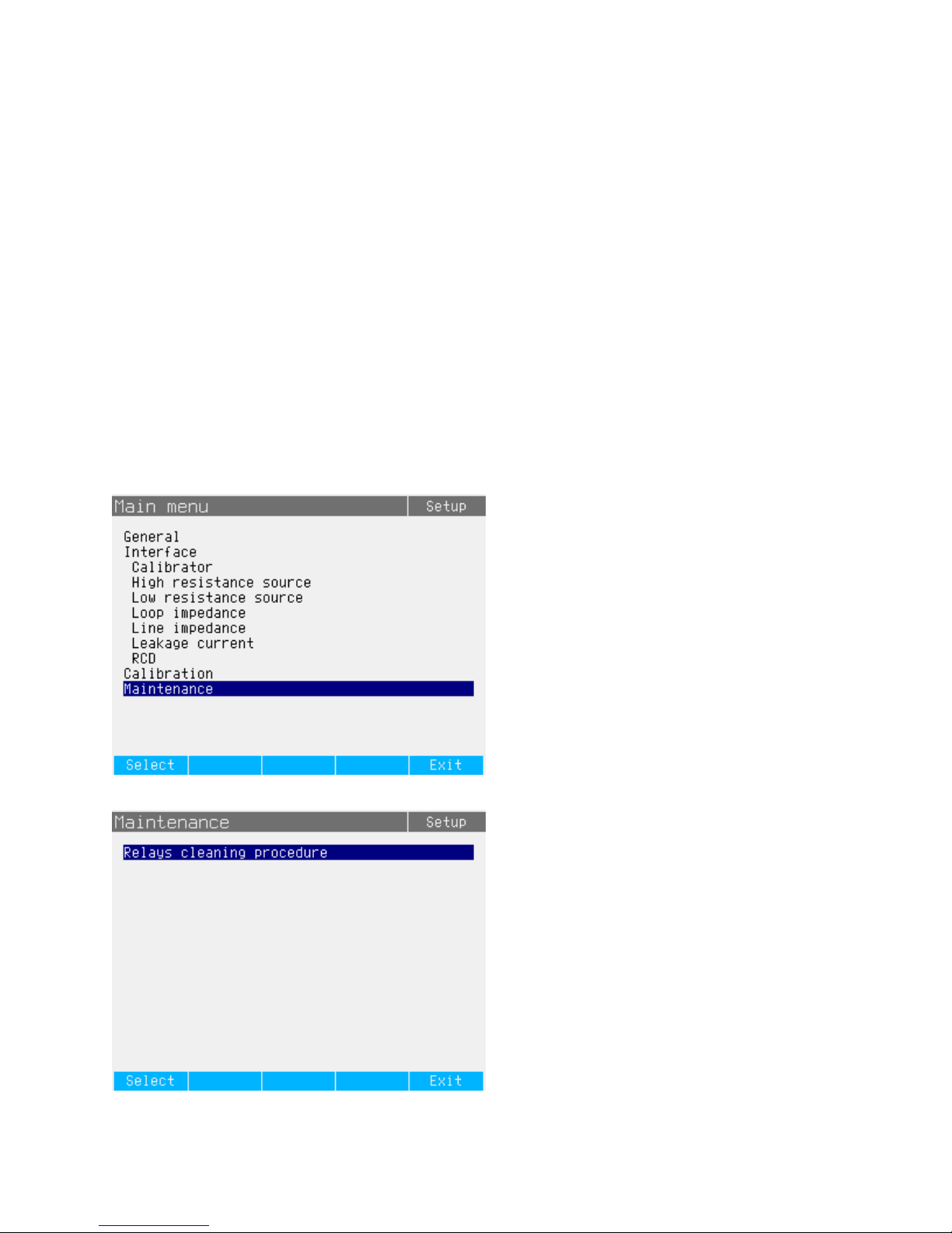
Note
For units with serial number lower than xx548xxxx, do not run the cleaning procedure
without connecting the external power supply. When the cleaning procedure is performed
without connecting the external power supply, the relay contact resistance may become
even worse. Changing the polarity of the dc supply source is recommended from cleaning
to cleaning to avoid one-way transport of contact material from one side of the contacts
to the other.
Change #9, 449
On page 1-7, add the following to the Symbols table:
ÃConforms to relevant South Korean EMC
Standards.
On page 1-9, add the following to the General Specifications:
Electromagnetic Compatibility (EMC)
International......................................IEC 61326-1: Basic Electromagnetic Environment
CISPR 11: Group 1, Class A
Group 1: Equipment has intentionally generated and/or uses conductively-coupled
radio frequency energy that is necessary for the internal function of the equipment
itself.
Class A: Equipment is suitable for use in all establishments other than domestic and
those directly connected to a low-voltage power supply network that supplies
buildings used for domestic purposes. There may be potential difficulties in ensuring
electromagnetic compatibility in other environments due to conducted and radiated
disturbances.
Emissions that exceed the levels required by CISPR 11 can occur when the
equipment is connected to a test object.
Korea (KCC).....................................Class A Equipment (Industrial Broadcasting & Communication Equipment)
Class A: Equipment meets requirements for industrial electromagnetic wave
equipment and the seller or user should take notice of it. This equipment is intended
for use in business environments and not to be used in homes.
USA (FCC) .......................................47 CFR 15 subpart B. This product is considered an exempt device per clause 15.103.
Change #10, 255, 468
On page 1-9, under WFuse Protection, replace the existing content with:
RCD input.........................................3.15 A, 250 V, Fast (F3.15H250V – 5 mm x 20 mm)
Meter amps (A) input........................20 A, 500 V, Fast (T20H500 V – 6.3 mm x 32 mm)
Loop/Line impedance input...............4 A, 500 V, Time delay (T4H500 V – 6.3 mm x 32 mm)
On page 4-6, following Table 4-2, replace the sentence with:
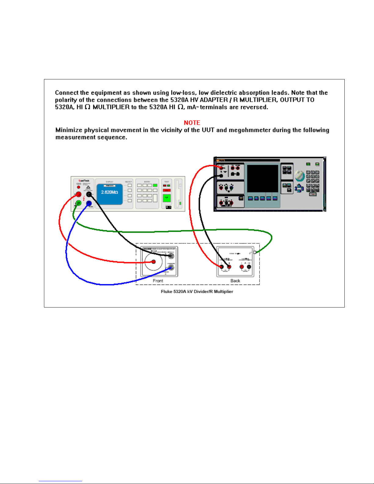
An optional resistance multiplier is offered to increase the range of high resistances from 350 MΩto
10 TΩand applicable dc test voltage to 5 KV. Resistance multiplier is based on a passive T-type
resistance network. Nominal value of multiplication is 1000. Exact value depends on resistance
multiplier calibration data. Input resistance of the multiplier is approximately-300 MΩ. Resistance
multiplier can be applied for calibration of such UUTs which use virtual ground (current to voltage
converter) as current sense terminal with input resistance. For UUTs with finite input resistance and
non-virtual ground on sense terminal, the input resistance must be taken into consideration. For this
purpose, the Calibrator is equipped with a parameter “R multiplier input”. Input resistance of sense
terminal of UUT should be written here to perform calibration correctly.
Note
Input resistance of the sense terminal is different for different models of megohmmeter.
Do not to set the parameter to the correct value. For megohmmeters with virtual ground,
0 Ωmust be written and saved here before calibration.