Fly Sky INr4-GYB User manual

INr4-GYB 接收机 Receiver
Http://www.flysky-cn.com
Copyright ©2022 Flysky Technology co., ltd
产品型号:INr4-GYB
适配发射机:所有支持 AFHDS 3 的枪控发射机
适合机种:车、船等
PWM 通道:4
无线频率:2.4GHz ISM
无线协议:AFHDS 3
天线类型:单天线
输入电源:3.5 ~ 9V / DC
数据输出:PWM/PPM/i-BUS2/S.BUS/i-BUS
温度范围:-10℃ ~ +60℃
湿度范围:20%~95%
在线更新:是
外形尺寸:17*29*16.6mm
机身重量:6.5g
认证: CE, FCC ID:N4ZINR4GYB0
INr4-GYB 采用 AFHDS 3(第三代自动跳频数字系统),
外置单天线带回传功能,内置陀螺仪,设计小巧轻便,
易于安装,支持 4 个 Newport 功能接口(Newport
接口可自定义输入或输出的信号类型:i-BUS2/S.BUS/
i-BUS/PPM 等),支持所有 AFHDS 3 发射机。
The INr4-GYB receiver adopts Flysky's third-generation automatic frequency
hopping digital system (AFHDS 3).It uses a single-antenna bidirectional
transmission system, with built-in gyroscope and is uniquely designed to
install. It supports 4 Newport function interfaces (Newport interface can
be customized with the input or output signal type: i-BUS2/S.BUS/i-BUS/
PPM, etc.). It adapts all transmitters which support AFHDS 3 protocol.
产品介绍 Introduction
接收机概览 Receiver overview
对码 Binding
产品规格 Product specication
[1] CH1(NPD)
[2] CH2(NPC)
[3] CH3(NPB)
[4] CH4(NPA)
[5] 对码按键
[6] BVD/VCC(电池电压检测 /供电接口)
[7] LED 灯
[8] 天线
[9] 信号脚
[10] +(电源正极)
[11] -(电源地)
[12] BVD 功能配件
[13] 接电池正极
[14] 接电池负极
[12] [13]
[14]
[1] CH1(NPD)
[2] CH2(NPC)
[3] CH3(NPB)
[4] CH4(NPA)
[5] BIND button
[6] BVD/VCC(Battery voltage detection/
Power supply interface)
[7] LED
[8] Antenna
[9]S(Signal Pin)
[10] + (Power anode)
[11] - (Power cathode)
[12] BVD harness
[13] Connect to battery anode
[14] Connect to battery cathode
Product Model: INr4-GYB
Adaptive transmitter: All surface transmitters which support
AFHDS 3 protocol.
Model Type: Cars or Boats, ect.
PWM Channels: 4
RF: 2.4GHz ISM
2.4G Protocol: AFHDS 3
Antenna: Single Antenna
Input Power: 3.5 ~ 9V/ DC
Data Output: PWM/PPM/i-BUS2/S.BUS/i-BUS
Temperature Range: -10℃ ~ +60℃
Humidity Limit: 20%-95%
Online Update: Yes
Dimensions: 17*29*16.6mm
Weight: 6.5g
Certication: CE, FCC ID:N4ZINR4GYB0
[6]
[8]
[7]
[10] [11] [9]
[4]
[5]
[3]
[2]
[1]
1. 使发射机进入对码状态 ;
2. 按住接收机对码按键同时上电后松开对码键(或者先给接收机上电后,长按对码键 3 秒),接收机指示灯快闪,表示进入对码状态;
3. 当接收机指示灯变为常亮时,对码成功 ;
• 当对码的发射机是单向模式进入对码状态时,接收机 LED 灯变为慢闪后将发射机退出对码状态,此时接收机 LED 灯常亮,表示
对码成功;
4. 检查发射机、接收机、模型是否正常工作。如需重新对码,请重复以上步骤。
1. Put the transmitter to enter bind mode;
2. Press and hold the receiver BIND button [5] while powering on the receiver, release the BIND button after receiver is powered on or
powering on the receiver rst, then press and hold the BIND button 3 seconds, the LED [7] of the receiver will ash rapidly, indicating
the receiver is in bind mode;
3. The binding process is complete when the LED of the receiver stops ashing and is on continuously.
• If a transmitter that has had its radio frequency (RF Standard) set to "AFHDS3 1 way" (please refer to your transmitter user
manual) enters bind mode, after the receiver LED becomes slow ashing, then put the transmitter to exit the binding state. At this
time, the receiver LED is solid on indicating the binding is successful.
4. Check to make sure the transmitter and receiver functions are working correctly, repeat steps 1 to 3 (binding process) if any problems
arise.
注:BVD 电压检测范围: 0~70V
Note: BVD voltage detection range: 0~70V

INr4-GYB 接收机 Receiver
Http://www.flysky-cn.com
Copyright ©2022 Flysky Technology co., ltd
智能车控功能介绍 SVC Function Instruction
智能车控功能是依靠陀螺仪对车辆油门和方向通道进行智能控制,即使在颠簸路况下或急剧转弯时,也能保证车辆
在预期的方向保持更好的行驶状态。需在发射机端完成该功能相关参数设置,以下以与 Noble Pro 发射机机适配为
例,介绍相关参数的意义,功能项包括 [ 中位校准 ]、[ 正逆转 ]、 [ 増稳模式 ]、[ 方向感度 ]、[ 油门感度 ]、[ 优先
级 ] 、 [ 陀螺仪校准 ] 和 [ 高级功能 ]。
[ 中位校准 ]:用于陀螺仪校准方向和油门中位,使车辆正常行驶时发挥最佳行驶状态。开启智能车控功能前,需将
车辆的方向舵量、中位微调和油门中位调至最佳行驶状态,完成后再进行中位校准。每次改变 [ 微调 ] 后都需进行
中位校准,中位校准过程中方向油门需置中位静止,待完成方可操作。
[ 正逆转 ]:设置陀螺仪混控通道的方向,默认为 [ 正向 ]。
[ 増稳模式 ]: 设置陀螺仪的工作模式,可设为 [ 普通 ] 或 [ 锁定 ],默认普通模式。
若设置为 [ 普通 ] 模式,当车辆偏航或转向时,陀螺仪自动根据所产生的角速度大小提供一个相反的补偿控制舵机
使其保持稳定或防止甩尾;
• [ 锁定 ] 模式仅在手轮回中保持的情况下有效,即车辆偏航时,陀螺仪会根据偏航角度反方向控制舵机使其回到
预期方向行驶。注:若 [ 锁定 ] 模式下手轮未回中,则同 [ 普通 ] 模式。
[ 方向感度 ] 设置矫正车轮按预期的方向行驶,当系统检测到车身将发生转动时,会自动通过车轮矫正车身。方向
感度是调节系统对车轮的矫正力度。
0% 表示混控舵机无陀螺仪辅助效果,100% 为陀螺仪辅助效果最大。
[ 油门感度 ] 设置陀螺仪介入油门调节的力度,应用于车辆转弯时油门扣机不变的情况下,陀螺仪混控降低油门输出,
使其能够快速安全地转弯。
固件更新 Firmware update
Update the rmware of the receiver by the transmitter which has bound with the receiver and has the built-in rmware of the receiver. You
can also update it by FlySky Assistant that establishes a connection with the transmitter.
While updating the rmware of the receiver, the transmitter is unable to bind with the receiver, the receiver need to update the rmware
mandatorily. There are two methods to let the receiver into forced update mode.
• Power on the receiver while pressing the BIND button or then approximately ten seconds, until the LED ashes three times and one o,
release the BIND button.
• Power on the receiver rst, then press and hold the BIND button 10 seconds, the LED of the receiver will ash three times and one o,
release the BIND button.
接收机固件更新可以通过对码已建立连接且内置了接收机固件的发射机更新;或者通过与发射机建立连接的遥控管家完成更新。
若更新接收机时,如无法与发射机对码建立连接,则需要手动强制更接收机固件,进入强制更新状态的操作方式有如下两种方式 :
• 按下对码按键,上电十秒钟后指示灯三闪一灭,松开对码按键;
• 先给接收机上电,长按对码键 10 秒后指示灯三闪一灭,松开对码按键。
失控保护 Failsafe
失控保护功能用于在接收机失去信号不受控制后,接收机按设置好的失控保护值进行通道输出以保护模型及人员安全。
本款接收机支持各通道单独设置失控保护,共支持三种失控保护模式 : [ 无输出 ]、[ 保持 ]、[ 固定值 ]。
[ 无输出 ]PWM 通道接口为无输出状态 ;
[ 保持 ] 输出失控前最后的通道值;
[ 固定值 ] 输出设置的通道值。
注:1. 对于 PPM/i-BUS/S.BUS/i-BUS2 等总线信号类型不允许单个或其中几个通道为 [ 无输出 ] 模式,通道设置为 [ 无输出 ] 模式时,
实际信号是保持最后输出值;
2. 因 S.BUS/i-BUS2 信号信息包含失控标志位,各通道失控保护设置被失控标志位传达给后续设备,若连接的设备支持失控标志位解析,
则失控后,输出各通道设置的失控保护值;
3. 对于无失控标志位的信号 PPM/i-BUS,支持设置失控时信号 [ 无输出 ] 模式。设置为 [ 无输出 ] 模式后,不管各通道失控保护如何设置,
失控后各通道均为 [ 无输出 ] 模式。
The failsafe function is used to output the channel value according to the out-of-control protection value set by the user after the receiver loses its
signal and is out of control to protect the model and personnel.
It can also be set failsafe for each channel respectively. This receiver supports three failsafe modes: [No output], [Hold], and [Fixed value].
[No output] It is no output for the interface of PWM;
[Hold] Keep the last output value;
[Fixed value] Output the failsafe values set for each channel.
Notes: 1. For bus signal types such as PPM/i-BUS/S.BUS/i-BUS2, a single or several of these channels are not allowed to be in [No output] mode.
The actual signal is held at the last output value when the channel is set to [No output] mode.
2. Because the S.BUS/i-BUS2 signal information contains failsafe ag bits, the failsafe settings of each channel are communicated to subsequent
devices by the failsafe ag bits. If the connected devices support the failsafe ag bit analysis, the failsafe values set for each channel are output
after out of control.
3. For the signal PPM/i-BUS without failsafe ag bits, it supports the setting of the signal to [No output] mode in case of out of control. After setting
to [No output] mode, regardless of the setting of the failsafe of each channel, each channel will be in [No output] mode after out of control.

INr4-GYB 接收机 Receiver
Http://www.flysky-cn.com
Copyright ©2022 Flysky Technology co., ltd
The smart vehicle control function is to control the vehicle throttle and steering channel intelligently through the
gyroscope. It can ensure that the vehicle is in the expected direction to maintain a better driving condition even
in case of bumpy roads or zigzagging. It is necessary to nish the parameter settings related to this function at
the transmitter side. Take Noble Pro transmitter as an example to introduce the meaning of related parameters,
including [Neutral Calibration], [Reverse], [ESP mode], [Steering Gain], [Throttle Gain], [Priority], [Gyroscope
Calibration] and [Advanced].
[Neutral Calibration]: Used for gyroscope to calibrate the steering and throttle neutral to make the best driving
condition when the vehicle is driving normally. Before enabling the smart vehicle control function, you need to
adjust the vehicle's steering servo volume, neutral trim and throttle neutral to the best driving condition. After
completion, start the SVC(Smart Vehicle Control) function for neutral calibration. It should be noted that the
neutral calibration is required after the adjustments of Trim. The steering and throttle need to be set to the neutral
position during the calibration process.
[Reverse]: Used to set the direction of the gyroscope in the mixing channel direction. By default, it is set to Normal.
[ESP mode]: Used to set the working mode of the gyroscope. It can be set to [Normal] or [Lock]. By default, it is
Normal mode. If it is set to Normal mode, when the vehicle is yawing or steering, the gyroscope automatically
provides an opposite compensation to control the servo to keep it stable or prevent it from drifting according to
the angular velocity generated.
• [Lock] The Lock mode is only eective when the steering wheel is kept in its self-centering state, (i.e., the vehicle
yaws), the gyroscope will control the servo in the opposite direction according to the yaw angle to make it travel
back to the expected direction. Note: If the steering wheel is non-self-centering in the Lock mode, the operations
are the same as those in Normal mode.
[Steering Gain]:Used to set the correction wheel to travel in the expected direction. When the system detects that
the vehicle body is aboutto move away from the intended steering, it will automatically correct the body through
the wheel. Steering Gain is to adjust the correction strength of the wheels by the system. 0%: No gyroscope
assisting eect for the mixing servo. 100%: maximum gyroscope assisting eect.
[Throttle Gain]: Used to set the strength of the gyroscope intervening in the throttle adjustment. It is applied to the
case that the throttle output is reduced through mixing control by gyroscope to enable the car to change directions
quickly and safely when the vehicle turns with the throttle trigger unchanged.
[Priority]:Used to set the control rate of Steering Gain when the vehicle turns, that is, the turning radius. For
example, in the direction turning by using the traversing steering wheel, when the value is 0%, the mixing control is
the strongest, that is, the turning radius is the largest. When the value is 100%, the mixing control is 0%, that is, the
turning radius is the smallest.
[Gyroscope Calibration]: Calibration is required when the gyroscope is enabled for the rst time or replaced. Before
calibration, keep the model in a stable and stationary state. Start the calibration. Then, the LED of the receiver will
be in twice- ash-one-o state. The calibration will automatically exit if it succeeds. If it fails, a prompt is given in a
pop-up window reminder.
[Advanced]: Use to be compatible with model drift cars, etc. You can set type of the model cars, and customize
parameters for [ST Wheel Gain], [Damper Point], [Damper] and [Filter].
• [ST Wheel Gain]: Adjustment of intervention ratio of steering operation to gyro control, It is more sensitive in the
steering control when the value increases.
• [Damper Point]: Adjusts the servo to the damper point in front of the target angle position. In the damping
interval, the servo oscillation speed will be slowed down. The higher the value, the larger the interval in which
the servo speed is slowed down.
• [Damper]: Slow down the servo speed in the damper point, and adjust the damping eect in the damper point.
The higher the value, the slower the servo slowing down in the damper point. As a result, it takes longer time for
the servo to reach the target angle. This parameter needs to be set together with [Damper point] to achieve the
best result.
[ 优先级 ] 设置设置车辆转向时,方向感度的控制比例,即转弯半径。例如转向时,当打方向手轮至最大行驶转弯时,
数值为 0 时,混控力度最大,即转弯半径最大,当数值为 100% 时,混控力度为 0%,转弯半径最小。
[ 陀螺仪校准 ] 第一次启用陀螺仪或更换陀螺仪时需进行校准。校准前,模型保持平稳静止状态,启动校准,此时
接收机 LED 灯两闪一灭,校准成功自动退出,若失败会弹窗提示。
[ 高级功能 ] 用于兼容漂移车等模型车。在此功能下,可设置模型车类型,可自定义 [ 手轮感度 ]、[ 阻尼区间 ]、[
阻尼设定 ] 和 [ 震动过滤 ] 参数。
• [ 手轮感度 ]:调整手轮控制输出比率,当数值增加时控制转向反应更快。
• [ 阻尼区间 ]:调整舵机到达目标角度位置前的阻尼区间。在阻尼区间内,舵机的摆动速度会被减慢。数值越高,
舵机速度被减慢的区间会越大。
• [ 阻尼设定 ] :在阻尼区间内减慢舵机速度,调整阻尼区间内的阻尼影响。数值越高,舵机在阻尼区间内的速
度会被减得越慢,舵机到达目标角度的时间越长。该参数需要搭配 [ 阻尼区间 ] 同时设置,以达到最佳效果。
• [ 震动过滤 ]:用于抑制抖动,数值越高抑制抖动越强。
注:
1. 仅 Noble Pro 发射机固件 1.0.2 及以上版本支持本接收机 SVC 的 [ 高级功能 ] 部分。
2. 若使用板控遥控器如 PL18 等,只能进行基础的使用,SVC 功能无法实现。
智能车控功能介绍 SVC Function Instruction

INr4-GYB 接收机 Receiver
Http://www.flysky-cn.com
Copyright ©2022 Flysky Technology co., ltd
认证相关 Certications
FCC Compliance Statement
This device complies with Part 15 of the FCC Rules. Operation is subject to the following two conditions: (1) this device may not cause harmful interference,
and (2) this device must accept any interference received, including interference that may cause undesired operation.
Warning: changes or modications not expressly approved by the party responsible for compliance could void the user's authority to operate the
equipment.
This equipment has been tested and found to comply with the limits for a Class B digital device, pursuant to Part 15 of the FCC Rules. These limits are
designed to provide reasonable protection against harmful interference in a residential installation. This equipment generates, uses and can radiate radio
frequency energy and, if not installed and used in accordance with the instructions, may cause harmful interference to radio communications. However,
there is no guarantee that interference will not occur in a particular installation.
If this equipment does cause harmful interference to radio or television reception, which can be determined by turning the equipment o and on, the user
is encouraged to try to correct the interference by one or more of the following measures:
-- Reorient or relocate the receiving antenna.
-- Increase the separation between the equipment and receiver.
-- Connect the equipment into an outlet on a circuit dierent from that to which the receiver is connected.
-- Consult the dealer or an experienced radio/TV technician for help.
EU DoC Declaration
Hereby, [Flysky Technology co., ltd] declares that the Radio Equipment [INr4-GYB] is in compliance with RED 2014/53/EU.
The full text of the EU DoC is available at the following internet address: www.yskytech.com/info_detail/10.html
RF Exposure Compliance
The distance between user and products should be no less than 20cm.
Environmentally friendly disposal
Old electrical appliances must not be disposed of together with the residual waste, but have to be disposed of separately. The disposal at the communal
collecting point via private persons is for free. The owner of old appliances is responsible to bring the appliances to these collecting points or to similar
collection points. With this little personal eort, you contribute to recycle valuable raw materials and the treatment of toxic substances.
FCC ID:N4ZINR4GYB0
Manufacturer:ShenZhen FLYSKY Technology Co., Ltd
Address: 16F, Huafeng Building, No. 6006 Shennan Road, Futian District, Shenzhen, Guangdong, China
本说明书中的图片和插图仅供参考,可能与实际产品外观有所不同。 产品设计和规格可能会有所更改,恕不另行通知。
Figures and illustrations in this manual are provided for reference only and may dier from actual product appearance. Product design and specicatiions may be changed without notice.
注意事项:
• 使用前必须确保本产品与模型安装正确,否则可能导致模型发生严重损坏。
• 关闭时,请务必先关闭接收机电源,然后关闭发射机。如果关闭发射机电源时接收机仍然在工作,将会导致遥控设备失控。失控保护设置
不合理可能引起事故。
• 确保接收机安装在远离电机,电子调速器或电子噪声过多的区域。
• 接收机天线需远离导电材料,例如金属棒和碳物质。为了避免影响正常工作,请确保接收机天线和导电材料之间至少有 1 厘米以上的距离。
• 准备过程中,请勿连接接收机电源,避免造成不必要的损失。
Attention:
• Make sure the product is installed and calibrated correctly, failure to do so may result in serious injury.
• Make sure the receiver's battery is disconnected before turning o the transmitter, failure to do so lead to lose control. Unreasonable
setting of the Failsafe may cause accidents.
• Make sure the receiver is mounted away from motors, electronic speed controllers or any device that emits excessive electrical noise.
• Keep the receiver's antenna at least 1cm away from conductive materials such as carbon or metal.
• Do not power on the receiver during the setup process to prevent loss of control.
智能车控功能介绍 SVC Function Instruction
• [Filter]: Used to suppress jitter. The higher the value, the stronger the jitter suppression.
Notes:
1. The [Advanced] section of the SVC function is only applicable to Noble Pro transmitter with rmware version 1.0.2 or later.
2. If you use a air transmitter such as PL18, it can only be used for basic purposes, and the SVC function cannot be realized.
Table of contents
Other Fly Sky Receiver manuals
Fly Sky
Fly Sky Tr8B User manual
Fly Sky
Fly Sky FS-R4D-ESC User manual
Fly Sky
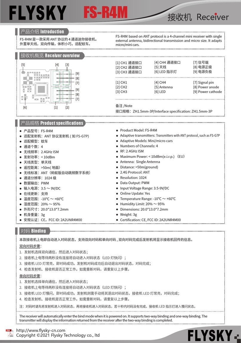
Fly Sky FS-R4M User manual

Fly Sky
Fly Sky FS-SRM User manual
Fly Sky
Fly Sky FS-R4D-BS User manual
Fly Sky
Fly Sky FS-A8S User manual
Fly Sky
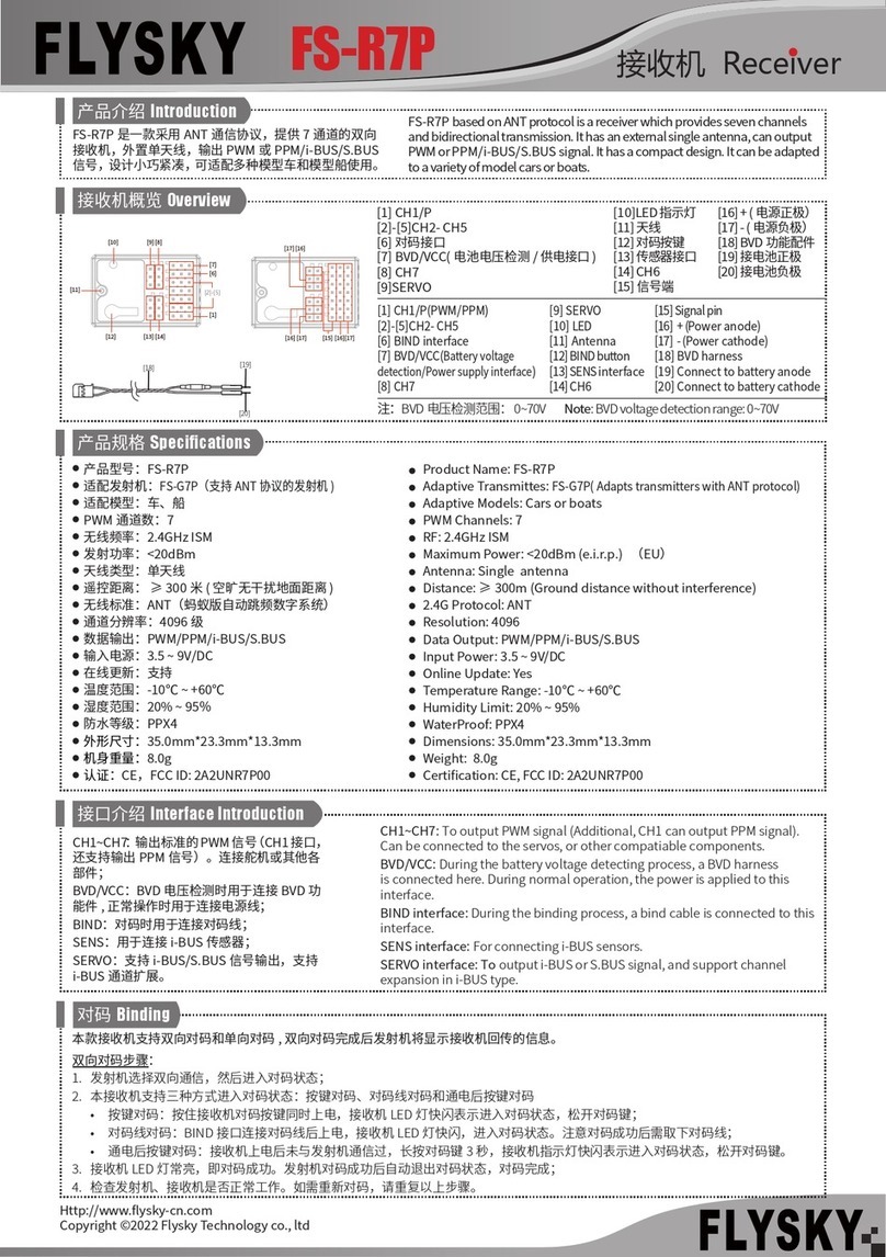
Fly Sky FS-R7P User manual
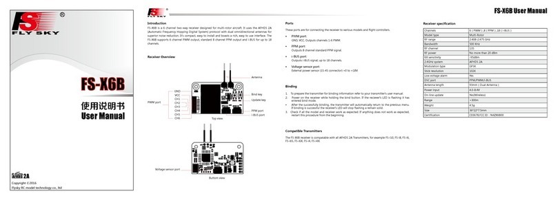
Fly Sky
Fly Sky FS-X6B User manual
Fly Sky
Fly Sky GMr User manual

Fly Sky
Fly Sky FTr10 User manual

Fly Sky
Fly Sky Tr8B User manual

Fly Sky
Fly Sky FTr8B User manual
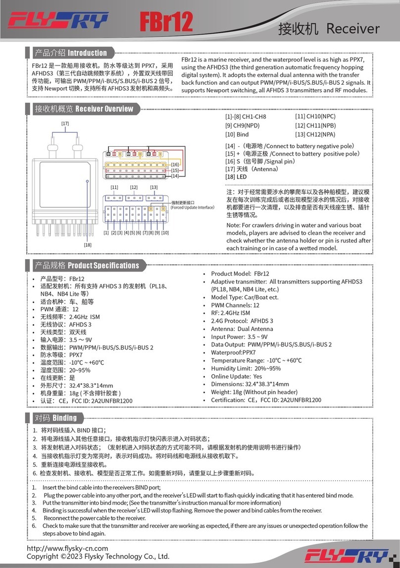
Fly Sky
Fly Sky FBr12 User manual
Fly Sky
Fly Sky FS-iA8X User manual
Fly Sky
Fly Sky FGr4 User manual
Fly Sky
Fly Sky FGr4B User manual

Fly Sky
Fly Sky FGr4S User manual
Fly Sky
Fly Sky FGr4D User manual
Fly Sky
Fly Sky FS-R4A User manual
Fly Sky
Fly Sky FS-SR8 User manual
