Flybox Vigilus User manual
Revision 1.0, 18/7/2017
For firmware version 2.14
Flybox
®
Operating manual

Page intentionally left blank

SECTIONS
INSTRUMENT CONFIGURATION
OPERATING INSTRUCTIONS
TECHNICAL SPECIFICATIONS

Flybox
VIGILUS - Operating manual
®
Rev. 1.0
Thank you for purchasing a Flybox® product. We hope
it fully satisfy you and makes your flights pleasant and
secure.
Developing Vigilus, our intent was to create a compact
but complete Engine Information System , easy to install
and use.
SYMBOLS USED IN THE MANUAL
NOTE: Used to highlight important informations.
CAUTION: Used to warn the user and indicate a potentially
hazardous situation or improper use of the product.
WARNING: Used to indicate a dangerous situation that can
cause personal injury or death if the instruction is
disregarded.

VIGILUS - Operating manual
Flybox
Rev. 1.0
®
Important notices & warnings
NOTE: Keep this manual in the aircraft.
This document must accompany the instrument in the event
of change of ownership.
NOTE: This device is intended for installation onto non type
certified aircraft only, because it has no aviation certifications.
Refer to your local aviation authorities to check if this device
may be installed in your aircraft.
CAUTION: Read entirely this manual before installing the
instrument in your aircraft, and follow the installation and
operating instructions described here.
CAUTION: The pilot must understand the operation of this
instrument prior to flight, and must not allow anyone to use
it without knowing the operation. Don't use this instrument
in flight until you are sure of the correct operating of the same.
CAUTION: When the installation is finished you must do a
test, prior to flight, switching on all the possible source of
electric noise and checking the properly operation of this
instrument.
CAUTION: The software of this instrument can be subject to
change, update, addition or removal of functions, so also the
operating mode of the instrument can be subject to change.
Always refer to the installation and operating manual updated
with the software version used in your instrument. To
obtain updated manuals, please visit www.flyboxavionics.it.

Flybox
VIGILUS - Operating manual
®
Rev. 1.0
Important notices & warnings
WARNING: Responsibility for installation lies entirely with the
installer. Responsibility for operations lies entirely with the
operator. Responsibility for any calibration, settings or any
other customization lies with the person performing these
operations.
WARNING: Do not solely rely on this instrument to determine
the primary engine informations. Always compare the
informations provided with other primary instruments to
recognize eventual malfunctions.
IMPORTANT: If you do not agree with the notices above
do not install this instrument in your aircraft, but return
the product for a refund.
Microel s.r.l. reserves the right to change or improve its
products. Information in this document is subject to changes
without notice.
WARNING: For safety reasons, the Vigilus operational
procedures must be learned on the ground.
WARNING: It’s up to the installer to check the correctness
of the settins for its engine, even using one of the Vigilus
preset, because engine manufacturers may change
parameters without notice. The engine preset of the Vigilus
are a help but needs to be checked by the installer.

VIGILUS - Operating manual
Flybox
Rev. 1.0
®
Contents
SECTION 1............................................................11
1.1 PRIMARY ACTIONS AFTER INSTALLATION....................11
1.2 PANEL INDICATORS AND COMMANDS.........................13
1.3 INSTRUMENT CONFIGURATION..................................14
1.3.1 ENTERING & BROWSING THE MENUs...........................14
1.3.2 MAIN MENU:.............................................................16
1.3.3 SETTINGS MENU:......................................................16
1.3.4 INSTRUMENTS MENU:................................................16
EGT SETUP MENU:........................................................17
CHT SETUP MENU:........................................................19
OAT (OUTSIDE AIR TEMP.) SETUP MENU:........................22
CAT (CARBURETOR AIR TEMP.) SETUP MENU:..................23
FUEL PRESSURE SETUP MENU:.......................................24
FUEL LEVEL SETUP MENU:.............................................26
OIL PRESSURE SETUP MENU:.........................................28
OIL TEMPERATURE SETUP MENU:...................................30
RPM SETUP MENU:........................................................32
MAP SETUP MENU:........................................................33
VOLT SETUP MENU:......................................................34

Flybox
VIGILUS - Operating manual
®
Rev. 1.0
AMP SETUP MENU:........................................................36
GB T (GEARBOX TEMPERATURE) SETUP MENU:................37
ROTOR SETUP MENU:....................................................39
1.3.5 GLOBAL SETTINGS MENU:..........................................41
AIRCRAFT SETUP..........................................................41
GPS SETUP..................................................................43
SERIAL PORTS SETUP...................................................43
AUDIO SETTINGS.........................................................44
UNITS SETUP...............................................................45
PAGES SETUP...............................................................46
1.3.6 FUEL COMPUTER MENU:.............................................47
1.3.7 ABOUT MENU:...........................................................49
1.3.8 FIRMWARE UPGRADE MENU:.......................................50
1.3.9 BACKUP AND RESTORE MENU:....................................51
1.4 FUEL FLOW TRANSDUCER CALIBRATION.....................52
1.5 FUEL LEVEL SENSORS CALIBRATION...........................54
1.5.1 FUEL LEVEL SENSORS CHECKINGS..............................58
1.6 FUEL COMPUTER ACTIVATION....................................59
SECTION 2............................................................60
2.1 USING THE VIGILUS.................................................60

VIGILUS - Operating manual
Flybox
Rev. 1.0
®
2.2 PAGE1: Main engine data page...................................61
2.2.1 TEMPERATURE PAGE..................................................68
2.3 PAGE2: Chronometer page........................................69
2.4 PAGE3: Fuel management page..................................71
2.5 PAGE4: Hourmeter page............................................75
SECTION 3............................................................77
3.1 ALARMS..................................................................77
3.2 SENSOR ALARMS......................................................78
SECTION 4............................................................79
4.1 DATALOGGER..........................................................79
SECTION 5............................................................84
5.1 VIGILUS DEFAULT CONFIGURATION TABLE..................84
TECHNICAL SPECIFICATIONS..........................................86
WARRANTY:..................................................................88

Page intentionally left blank

VIGILUS - Operating manual
Flybox
11
Rev. 1.0
®
SECTION 1
1.1 PRIMARY ACTIONS AFTER INSTALLATION
WARNING: Do not fly until you have performed at least
the actions indicated below:
1 - Select the engine type: the first parameter to setup is the
engine selection, because it reset all the parameters to the
default value. The engine selection can be made by entering in
the Main menu → Settings → Global Settings → Aircraft as
explained in chap.1.3.5.
2 - Tank level sensors: (if connected). It's indispensable to
perform the calibration for all the tank level sensors connected
to the Vigilus. Without performing calibration and settings no
indication will be furnished.
It is responsibility of the user to check during the first flights
and over time the goodness of the calibration and therefore
the instrument indications.
The verification can be done in any moment, for example b y
simply checking the quantity put to fill the tank: if you k n o w
that the tank filled contain 40 liters and the Vigilus i n d i c a t e
as remaining quantity 10.0 liter, you know that to fill the tank
you must put approximately 30 liters. Of course keeping in
mind that in ground the indications will be different that in
flight because of the flight's attitude. This problem is present
also in the traditional analog gauge indicators, but is more
difficult to detect because of the non-numeric indication.
Another verification is, in case of low remaining quantity (i.e.
4~5 liters), drain and measure it.

Flybox
VIGILUS - Operating manual
12
®
Rev. 1.0
Primary actions after installation
3 - Fuel computer: (if installed). If it's installed the fuel flow
transducer, BEFORE rely on informations provided by the fuel
computer section you must:
- Verify that the K-factor set in the Vigilus is pertinent to the
installed fuel flow transducer (for the Flybox® TFTHP is 416400).
- Execute the fuel flow transducer calibration as explained in
chapter 1.4. Without calibration the fuel computer
informations may be wrong, even if the nominal K-factor is
correct for the fuel flow transducer used.
After calibration, the K-factor should have been calculated
automatically and at best for every single installation. You must
still check for some time if the remaining quantity indicated are
reliable compared to the refuelling performed. For example, if
the instrument indicate a remaining quantity of 35 liters and you
know that the tanks capacity is 80 liters, filling the tanks should
require approximately 45 liters; in case of much difference redo
the calibration.
Consider also that, during use, little errors accumulate and if
you never fill the tanks you never “reset” all these errors.

VIGILUS - Operating manual
Flybox
13
Rev. 1.0
®
F1
pushbutton
Display
Knob with
pushbutton
1.2 PANEL INDICATORS AND COMMANDS
The knob with pushbutton can be rotated (for example to
increment or decrement a value) or pressed like a pushbutton
(for example to enter in a submenu).
Inside the menus it’s always indicated the meaning of the
pushbuttons (for example: exit, back, etc…)
●Display cleaning:
To clean the display use the supplied smooth cloth, slightly
moistened with cleaner. Use a cleaner that is specified as safe
for anti-reflective coatings.
CAUTION: Avoid any chemical cleaners or solvents that can
damage the display anti-reflective coating or plastic
components. Do not use cleaners containing ammonia.Do not
spray water or cleaner directly onto the display.
F2
pushbutton
Flybox
VIGILUS - Operating manual
14
®
Rev. 1.0
1.3 INSTRUMENT CONFIGURATION
Before using the Vigilus you need to configure it; read
completely this chapter and follow step by step the
sections to completely configure all the sensors, alarms
and preferences available.
1.3.1 ENTERING & BROWSING THE MENUs
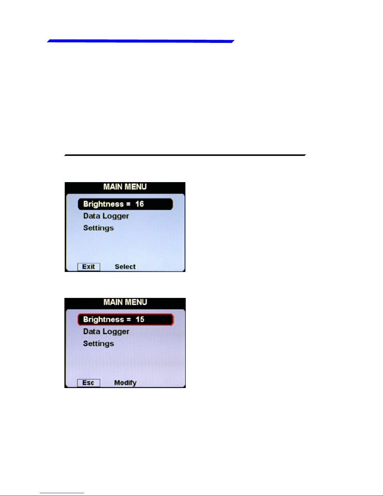
Press the knob for 1 second to enter in the main menu:
●Press the “EXIT”
pushbutton to exit the
menu.
●Rotate the knob to select
an item of the menu.
●Click the knob to enter in
the selected item.
For example, to change the display brightness:
●Rotate the knob to select
the “Brightness” item.
●Click the knob and the item
become highlighted in
flashing red: it means that
you can edit this value by
rotating the knob.
●Click again the knob to
store the new value for the
brightness OR press the
“ESC” pushbutton to exit
without saving the
changes.
VIGILUS - Operating manual
Flybox
15
Rev. 1.0
®
Entering & browsing the menus
Instrument configuration
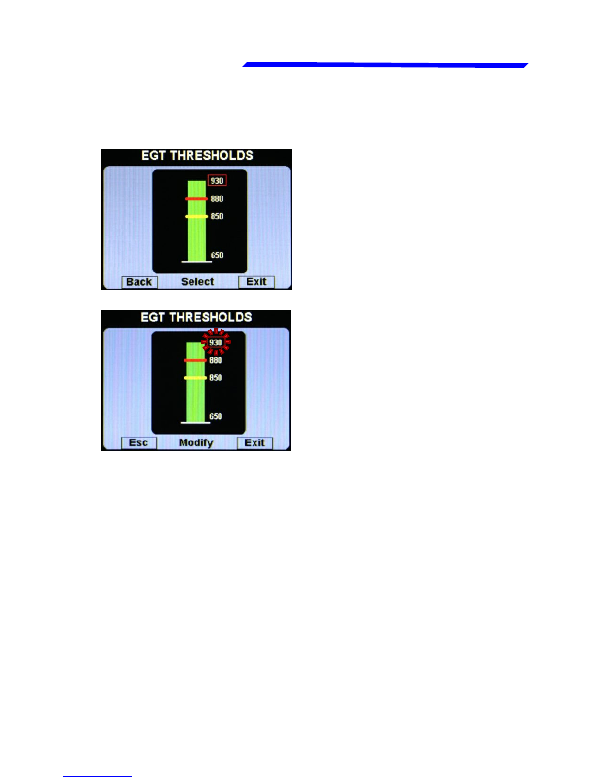
Also when inside a parameters page, the editing
philosophy is the same, for example:
On this example, by rotating
the knob you select the
parameter that you want to
edit (the selected
parameter is highligted in
red).
If you don’t want to store the new value press “Esc”
pushbutton to cancel the editing or press “Exit” pushbutton
to exit the menu and return to the main pages.
If you click the knob the
highlight become flashing
red to indicate that you are
editing that parameter.
Rotate the knob to change
the value and press the
knob to store the new value
Flybox
VIGILUS - Operating manual
16
®
Rev. 1.0
Instrument configuration
●Brightness: display brightness adjustment (1=min. brightness,
16=max. brightness). Default value=16.
●Data Logger: enter in the datalogger menu (see section 4).
●Settings: enter in the settings menu (see next chapter).
1.3.2 MAIN MENU:
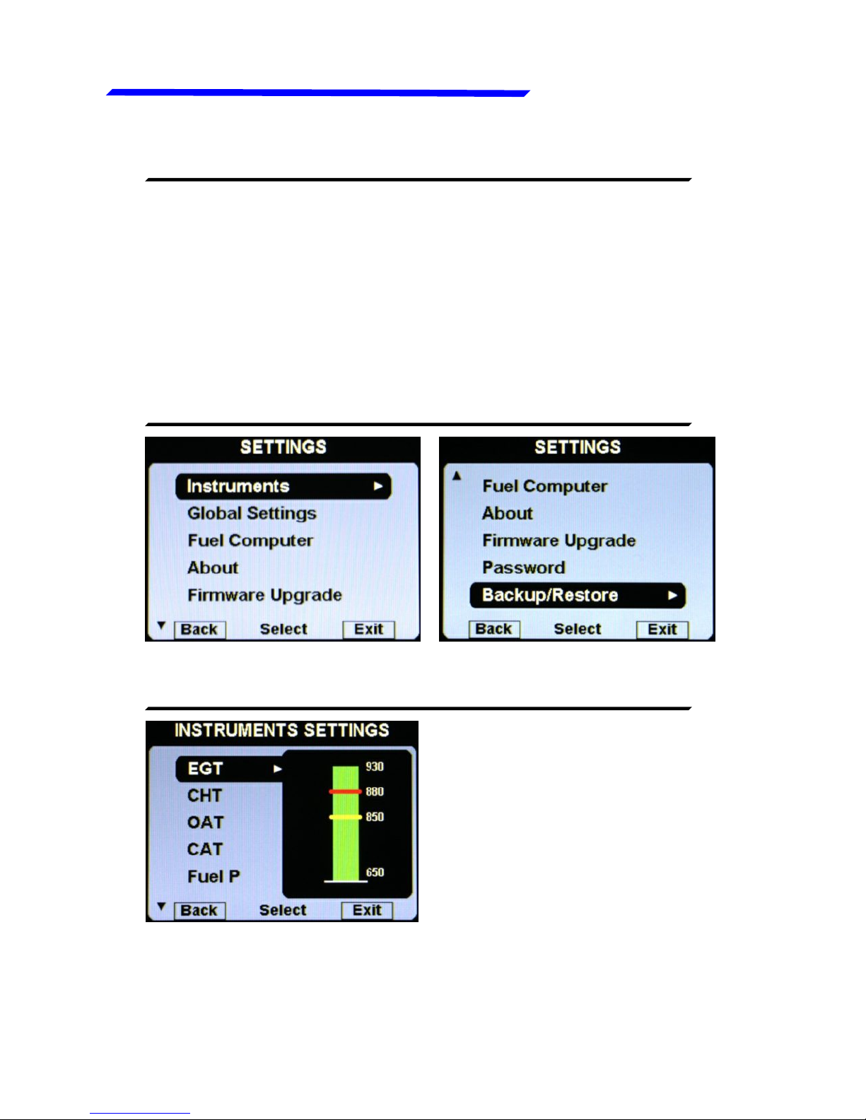
1.3.3 SETTINGS MENU:
1.3.4 INSTRUMENTS MENU:
On this menu you can set all the parameters for each available
measurement. On the right window there is a preview of the
thresolds for the selected item; click the knob to enter in a item.

VIGILUS - Operating manual
Flybox
17
Rev. 1.0
®
Egt setup menu
●Thresholds: set the
thresholds of the EGT bars:
min value (bottom of the bar),
yellow threshold, red
threshold and max value (top
of the bar).
●Mapping: although we
recommend to perform a
clean installation, with this
feature it’s possible to
reassign or disable the
different EGT inputs available
in the remote module: for
example you can assign the
input#1 of the remote module
EGT SETUP MENU:
●EGT THRESHOLDS SUBMENU:
●EGT MAPPING SUBMENU:
to the engine cylinder#3 and so on. You can also disable each
inputs, useful for example if a sensor fails and you don’t want
to display the indication for that sensor.
Instrument configuration
Flybox
VIGILUS - Operating manual
18
®
Rev. 1.0
Egt setup menu
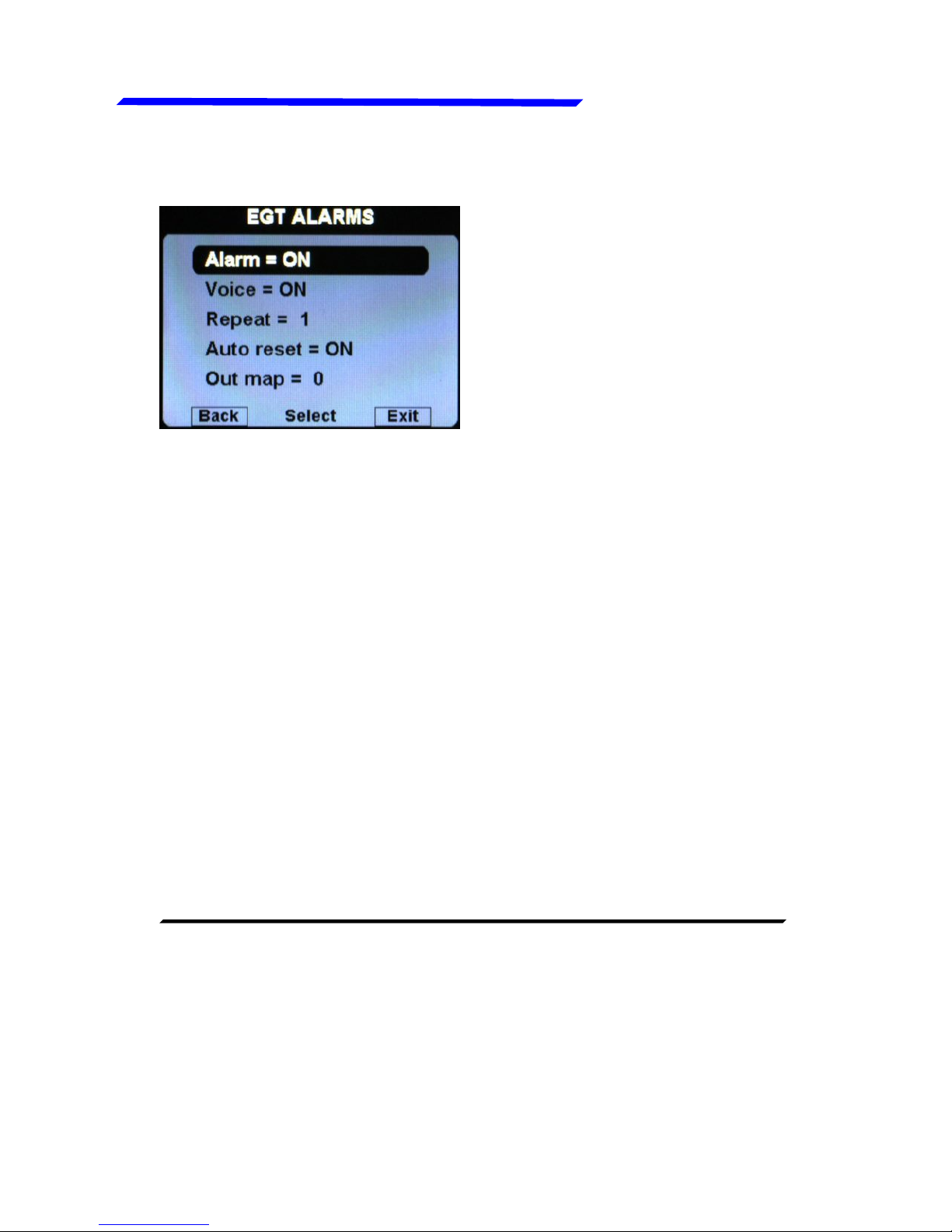
●Alarm = ON/OFF:
enable/disable the alarm
(alert indication on display)
that occurs when a EGT
measurement exceeds the
red threshold (default=ON).
●Voice = ON/OFF: enable/disable the audio alert notification on
EGT alarms (default=ON).
●Repeat: Set the number of times that the vocal alarm for the
EGT is repeated on the audio output (range:1~5, default=1).
●Auto reset = ON/OFF: if set to ON, if a alarm condition is
activated but the measurement that activated this alarm has
dropped below the alarm threshold, the Vigilus automatically
reset the alarm indication. If set to OFF, the user must manually
reset the alarm indication, even if the measurement that
activated this alarm has dropped below the alarm threshold
(default=ON).
●Out map: you can choose to enable one of the four outputs
available on the remote module when the alarm is activated,
useful for example to turn on an alarm light on the cockpit.
Set to zero to disable this function (default=0).
●Unit: °C / °F: Set the unit of measure for the EGT temperatures;
choose between °Celsius (°C) or °Fahrenheit (°F). Default=°C.
●Filter: This parameter affect the readings and the gauges
displayed: a low value means that the readings will be more
fast and unfiltered (but subject to fluctuations), an high value
means that the readings will be more slow and stable (range:
0~999, default=100).
●EGT ALARMS SUBMENU:
Instrument configuration

VIGILUS - Operating manual
Flybox
19
Rev. 1.0
®
Cht setup menu
●Thresholds: set the
thresholds of the CHT bars:
min value (bottom of the bar),
yellow threshold, red
threshold and max value (top
of the bar).
●Mapping: although we
recommend to perform a
clean installation, with this
feature it’s possible to
reassign or disable the
different CHT inputs available
in the remote module: for
example you can assign the
input#1 of the remote module
●CHT THRESHOLDS SUBMENU:
●CHT MAPPING SUBMENU:
to the engine cylinder#3 and so on. You can also disable each
inputs, useful for example if a sensor fails and you don’t want
to display the indication for that sensor.
CHT SETUP MENU:
Instrument configuration

Flybox
VIGILUS - Operating manual
20
®
Rev. 1.0
Cht setup menu
For example, for Rotax 912/914 engines the default situation
will be the following:
Since the Rotax engines are provided with two CHT sensors,
but the first is for the cylinder#2 and the second is for the
cylinder#3, this configuration make sure that the first input of
the remote module (where is connected the first sensor) is
referred to the cylinder#2, while the second input of the remote
module (where is connected the second sensor) is referred to
the cylinder#3; the third and fourth inputs are disabled (Enab.
= OFF).
●Alarm = ON/OFF:
enable/disable the alarm
(alert indication on display)
that occurs when a CHT
measurement exceeds the
red threshold (default=ON).
●CHT ALARMS SUBMENU:
●Voice = ON/OFF: enable/disable the audio alert notification on
CHT alarms (default=ON).
●Repeat: Set the number of times that the vocal alarm for the
CHT is repeated on the audio output (range:1~5, default=1).
Instrument configuration
Table of contents
Popular Automobile Electronic manuals by other brands


Connects2
Connects2 CAM-KIT15 user manual
![ADS AKX-FO(RS)-FO1A-[AKX-FO1]-EN install guide](/data/manuals/22/l/22l04/sources/ads-akx-fo-rs-fo1a-akx-fo1-en-manual.jpg "ADS AKX-FO(RS)-FO1A-[AKX-FO1]-EN install guide")
ADS
ADS AKX-FO(RS)-FO1A-[AKX-FO1]-EN install guide

Westfalia Automotive
Westfalia Automotive Autocode-Mini Getting started guide

GEMINI TECHNOLOGY
GEMINI TECHNOLOGY 514F user manual

Voyager
Voyager PA500 Owners & installation manual

Nokia
Nokia 616 installation instructions

Rear view safety
Rear view safety RVS-813613-NM instruction manual

SwedeSolutions
SwedeSolutions CFE Plus installation manual

Banner
Banner Magnetic Vehicle Sensor M-GAGE brochure

PAC
PAC NU-CHY1 Installation Parts Guide

ECVV
ECVV FV Rover Jaguar MixCAM installation manual

Connects2
Connects2 CTUKI01 instruction manual