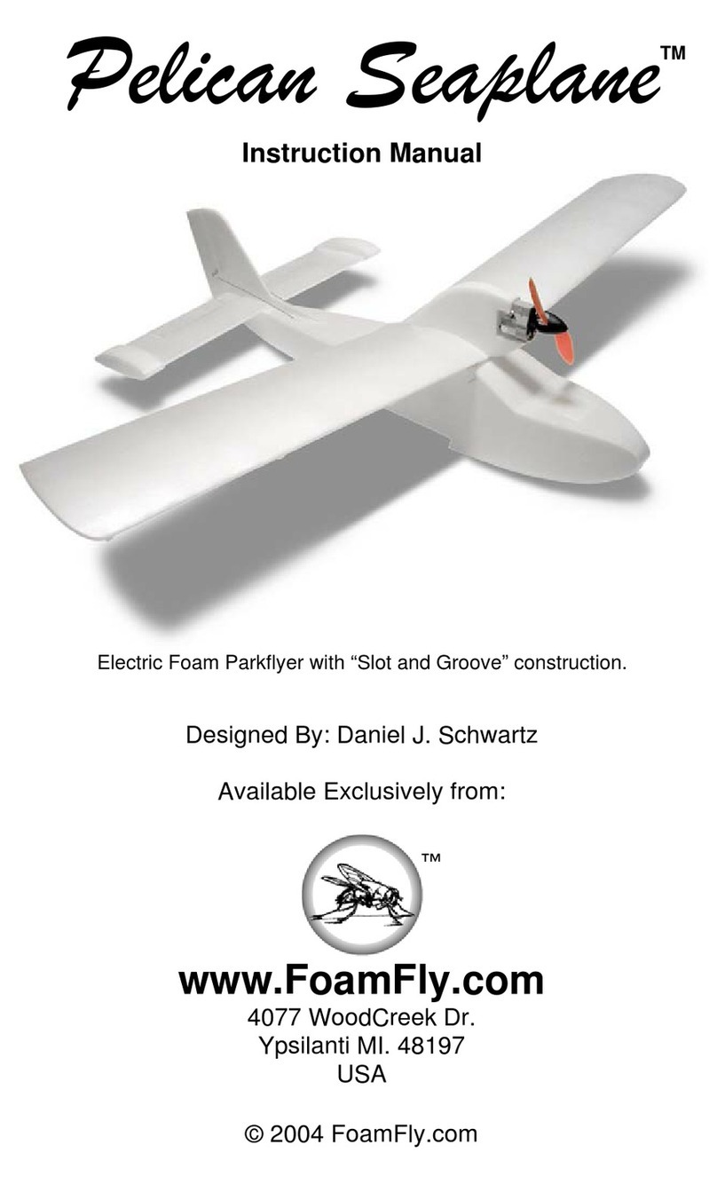
FoamFly Gremlin User manual

TM
Gremlin
Instruction Manual
Electric Foam Parkflyer
Designed By: Dan Schwartz
Available Exclusively from:
www.FoamFly.com
4077 WoodCreek Dr.
Ypsilanti MI. 48197
USA
© 2006 FoamFly.com
!


©2006 FoamFly.com 2
Thank you for purchasing the FoamFly Gremlin! If you’re reading this, you’ve
probably already been charmed and cannot resist building and flying one. You
may not ever see another plane like it. This is the state of the art in foam
building kits. Who said foam had to be flat??? A plane every bit as nice as those
“made in china” kits, but you build it yourself. You’ll know this plane inside and
out.
All the pieces are specially designed to interlock, and are computer cut so that
they fit perfectly every time.
Gremlin Specs:
•Wingspan: 36”
•Ready To Fly Weight 10-14 Oz.
•Motor (x2): GWS EPS-300c (or CD-Rom, or Brushless)
•Propeller: 7”-9” (9x7 3-Blade Recommended)
•Batteries: 2-3 cell 1200mAh Lithium Polymer, or 8-9
cell NiMHs. Basically any 1.5 – 2.5 Oz
battery.
•Receiver: GWS R4P (or other 4 Channel)
•Servos: GWS Pico BB (or Hitec HS-50)
•ESC: GWS ICS-300 (15-Amp Speed Control for
brushed setups)
Introduction:
FoamFly.com is more than just a hobby company. It’s a community too!
With pilots and designers from all over. Please take pictures and videos of your
Gremlin, and I’ll put them in the photo gallery. Feel free to drop by and see what
all the other foam junkies have been building. There are free plans, and lots of
tips and ideas as well as unique new planes that you won’t find anywhere else.
NEW!! FoamFly kits are now easier to assemble. New techniques make all the
most tedious steps unnecessary.
Okay, you’ve got your Gremlin kit spread out in front of you. I know it looks
complicated, but take it one step at a time, and you won’t find it very difficult.
(They always say this but, “I highly recommend that you read the entire
instruction manual before beginning.”) Just remember to test fit each piece
before gluing, and if you get frustrated, just take a break, and have a soda. You
don’t have to finish this plane in one sitting.
There are some techniques you’ll need to be familiar with to make the most
of your kit. I’ll refer to them as they’re needed, but the details of those
techniques will be in the Appendix at the end of this manual.
Don’t let all the text in this manual scare you. Here we go.

3
1) Identify all the parts:
You’ll need to know which part is which, unless you want to end up with the
flying equivalent of Frankenstein’s Monster. So, let’s start by taking a look at
what you’ve got here.
a) Foam Airplane Parts:
(1) Center Keel
(2) Fuselage Formers
(3) Fuselage Bottom
(4) Fuselage Top
(5) Hood
(6) Rudder
(7) Horizontal Stabilizer & Elevators
(8) Wings (2)
(9) Wheel Pants
A little trimming of the parts sheets reveals an easy to assemble collection of
parts.
And of course even a foam plane needs a few odds and ends to tie
everything together. Take a few moments to inspect what you’ve got here.
As the items are called for you’ll get more info on their intended uses.
b) Non-Foam Parts:
i) Plastic Control Horns
ii) Wire for Pushrods
iii) Wire to Join Elevators
iv) Wire for Aileron Torque rods
v) Wheels
vi) Aluminum Axles
vii) Landing Gear Supports
viii) Wood for Motor Mounting (Depends on which motor type)
ix) 2-Liter Soda bottle
2) Let’s Begin:
Assemble the main Fuselage
a) Fit the formers into place in the fuselage. It’s easiest to glue each one
before proceeding to the next. Working from the rear, slip a former into

©2006 FoamFly.com 4
the slot on the keel, and Hot Glue it into place (See appendix section,
“Gluing: Hot Glue Welding”)
i) Repeat the process for the middle former.
ii) The Firewall Former takes a little care to slip into place. Slip it in at
a slight angle, and then straighten and drop it into the slot. Weld
the former into place at each point, being careful not to get glue into
the slot where the motor mount stick will go.
b) Peel one side of the fuselage bottom. (This will be the inside) Next,
use your knife to split the tab at the rear end of the piece. Carefully
bend the foam into a curved shape that matches the bottom of the keel
as closely as possible. (See appendix section, “Rolling the Foam”)
c) Test fit the bottom in place. The
split tab will fit on either side of the
rudder, and snap into the holes
there. Once you’re comfortable
with the fit, glue the bottom in with
the contact cement. (See
appendix section, “Gluing: Contact
Cement”) For extra strength, hot
glue weld the bottom in place from
the inside afterward.

5
d) Peel the inside of the Fuselage top. Gently
roll the foam till it is a good fit over the tops
of the formers. (See appendix section,
”Rolling the Foam”) Be especially careful
when bending the rear portion, as the bend
is quite sharp. Go slowly, and check the fit
often. Be sure that the elevator slots all line
up straight when the part is in place, and
that the bottom edges fit flush.
i) Glue the fuse top in place with the contact cement. Make sure that
the top section is properly centered, and that everything lines up as
noted above.
ii) Hot Glue Weld the seams where the rudder exits the fuselage on
the bottom.
Ta Da!!! Make sure the especially that the tail and wing slots line up.
3) The Wings: Cut a piece of the 3mm carbon fiber to an 11.5” length. Press
it into the slot in the bottom of the wing, and hot glue weld into place.
a) Form an airfoil into each wing by rolling the foam. The grooves go on
the bottom of the wing, so make sure you end up with both a left and
right wing. Check the fit against the slot in the fuselage, and the top of
the wheelpants to see if your airfoil is the correct shape. You
“massage”
the

©2006 FoamFly.com 6
leading edge a little with a finger and thumb to make sure that it’s a
good fit.
b) Run a length of strapping tape on the bottom of each wing. One just
under the leading edge, and the other just in front of the aileron slot.
c) Tape hinge the ailerons into their places
in the wing. Get out the torque rods.
You’ll notice they’re much longer than
they need to be. We’ll be cutting them
down, but save the excess to make the
elevator joiner wire. Starting at the end
of the torque rod with the loop on it, cut it
down to a ??” Length. Slide a two small
pieces of the black tubing over the pushrod before making the next
bend.
d) Bend a 3/4” section at the end of each torque rod to a 90 degree angle
on one direction, but a 75 degree angle in the other (see picture)
Repeat for the other torque rod, but in mirror image. It is VERY
important that you end up with a separate left and right torque rod.
Also, don’t forget to put the black tubing on the second one…. I did. ;)
e) Fit the loop of each torque rod
through the cutout in the wing, then
glue the tubing into the grooves to
support the torque rods. Cut a small
groove into the bottom of each
aileron where the end of the torque
rod will be glued in place. Slip
another piece of the black tube over the end and glue the tubing into
place. Do not glue the wire into any of the tubes, they must be able to
slide freely.
f) Make a small slit in the wing leading forward from the torque rod hole on
the top side. This will allow you to press the loop of wire down into the
foam. Once the loop of wire is flush with the foam, you’ll be able to slide
the wing into the fuselage.
g) The wings will each have about 5 degrees of dihedral. Test fit the wing,
when you’re sure you know how it will fit, run a bead of hot glue along
the base of the wing, and slide it into place. Once that glue has set, Hot
Glue Weld the wing in place from the outside of the fuse. It’s going to be
a bit easier if you put in the aileron servo before gluing the second wing
into the slot. Make sure that you’ve centered the servo, and gotten the
control horn on straight before putting it in the plane. Fish the servo

7
wire through the lower hole in the former into the front compartment, or
out behind the wing depending on where you’ll mount the receiver..
Then, repeat all this and attach the other wing.
4) The Control Surfaces:Tape hinge the two halves of the elevator into place
on the horizontal stabilizer. Slide a couple of small pieces of small black
tubing over a piece of .047” wire. Put a 90 degree bend in one end of the
wire, and another on the other side of the tubing so that you have a U shape
that is 1” on each end, and 2” in the middle.
a) Glue the tubing into the slot in the center of the fuselage so that the wire
is free to rotate. Center the joiner in the slot, and cut a small grove in
the bottom of each elevator half. Slip another small piece of black
tubing on the ends of each side of the “U” and glue them into the
grooves that you just cut in the elevator. Do not glue the wire into any of
the tubes, they must be able to slide freely.
b) Carefully slide the completed horizontal stabilizer through the slot in the
fuselage. Make sure that it is straight and centered, and hot glue weld
the horizontal stabilizer in place.
c) Tape Hinge the Rudder in place, and trim off the excess tape.
5) Radio Gear:You might have already
installed the aileron servo, but if not you’ll
want to do it now. The servo should fit into
the small pocket between the wings. Use
your hot glue gun to “rivet” the servo into
place.
a) Decide where to put the rest of the gear. If you’re going to use a very
lightweight motor, and
small battery, you can
mount the servos on either
side of the center keel, in
the front section. If you’re
using a heavier motor and
battery, you can mount the
servos and receiver back in
the cabin area. In either
case, mounting the servos with double sided tape is the easiest way.
The pushrods should go through the foam leading from the control
surface where the horn will be, to the servos in the straightest line
possible. This usually means that the servo will be on the opposite side

©2006 FoamFly.com 8
from the horn with the pushrods crossing in the middle. Mount the
receiver with double sided tape also.
b) Attach the control horns to the surfaces where the pushrods will line up
with them. Make a small slit in the foam and insert the control horn.
Position it so the hole lines up directly over the hinge line. When
everything lines up hot glue weld the horns in place.
c) Connect the pushrods to the servos. I highly recommend the Dubro E/Z
Connectors. They make life a lot easier when it comes to connecting
pushrods to your servos. You could also use a z-bend at each end and
a v-bend in the middle for adjustments. Fit the rubber grommets into
the loops in the aileron torque rods, and press a z-bend from the
pushrod into the grommet. You’ll probably need to use needle nosed
pliers for this. Connect the other ends of the aileron pushrods to the
aileron servo. Hook up the pushrods for the elevator and rudder now
too.
6) Motor Mount: The kit comes set up to mount a geared motor. Glue the motor
stick into the slot in the firewall. Put a little hot glue on the back of the stick
and push it into place. When that glue has set, hot glue weld the stick in
place. Slide the gearbox onto the stick, while fishing the motor wires
carefully into the plane. I highly recommend using a set screw to hold the
motor onto the stick. An extra servo mounting screw works nicely.
7) Finishing Touches: Peel the inside of the hood, and roll it to be just round
enough to sit nicely on the front formers. You might need to sand the edges
on the bottom sides to be a tighter fit. Tape hinge the hood in place on one

9
side. Place a piece of tape on the fuselage side opposite from the hinge, as
an attachment point. Use another piece of tape on the hood itself. Folding a
small lip on the edges makes it easy to get a grip on the tape for opening the
hood.
a) Assemble the wheelpants. Lay out the left and right halves of one set,
and cut the wood reinforcement sticks to the length of the pre-cut
grooves. Run a bead of
hot glue down a groove,
and press the stick in.
When both sticks are in
one half, get your contact
cement and prepare the
other half. When you’ve
got contact cement on
both halve, ready to go, run a bead of hot glue in the grooves on the
second half, and then quickly press the two halves together.
b) Some of the wheels are thicker than others, so you might need to
“squeeze” the foam a little so the wheels will spin freely. After checking
on the wheel fit, glue the outer sides on the wheelpants. Pop the wheel
in place, and slip the aluminum axle through the holes. Glue the Axle in
place. A couple of drops of foam-safe CA glue work perfectly. (Careful
not to glue the wheels in place too. They gotta spin!)
c) Glue the wheelpants to the bottom of the wings at an equal distance
from the center. Use the contact cement, and when they’re firmly in
place, hot glue weld around the base where it meets the wing.

©2006 FoamFly.com 10
d) Finished that soda yet? Tape the canopy
template on the side of a 2 liter bottle, and
trim the bottle shape to match. Follow the
general curve of the top as the cutouts are
only to make it easier to bend.
e) The canopy can be held in place with
scotch tape (again a folded tab makes it
easier to pull up again later) or you can
install some Velcro on both the foam and
the canopy
8) Test everything: Power everything up, and check the usual suspects.
Make sure that the control surfaces move in the right directions, and that the
prop spins the way it should. Make sure that you have good aileron
differential. That is, each aileron should move about twice as far up as id
does down. Decide on a location to mount the battery. It will either go up
front, slid partially under the wing, or in the main cabin mounted on top of the
wing out of the way of the aileron pushrods. You want the CG to be at or
just in front of the wing.
9) Flying: You won’t need very extreme throws to fly the Gremlin,
especially if you fly in a reasonably sized field. The plane responds very well
to rudder input, and if you’re not comfortable flying 4 channels, you can
either mix some rudder input with aileron using your transmitter, or you can
connect the rudder to the aileron servo for automatic mixing. Only about
40% rudder to 100% aileron is required for super smooth turns.
a) Aerobatics are possible, but not the primary design goal of the Gremlin.
Still, loops and rolls are possible. Touch and goes are loads of fun.
You’re Done!
You’re still reading? Go fly already. ;)

11
APPENDIX:
The Tools: (and things you’ll need)
1) Knives: a Razor knife, and an X-Acto would both be useful.
2) Glue: UHU Creativ` contact cement, or White glue, or Epoxy. AND, you’ll
definitely want a hot glue gun and glue sticks.
3) Tape: You’ll want 2” wide clear packing tape, or some “crystal clear” Scotch
Tape if you can find it.
4) Pliers: Something suitable for wire bending.
The Techniques: You’ll probably want to practice these on a piece of the scrap
foam.
1) Gluing:
a) Contact Cement:
The contact cement will test your patience. I know you’ll be
tempted to stick the pieces together immediately, but don’t give in. The
UHU Creativ’ will form the strongest bond, if you allow it to dry for AT
LEAST 5 minutes before putting the pieces together, and probably
much longer. Put the glue on BOTH surfaces to be joined. If you’re not
used to contact cement, remember you really only get ONE CHANCE at
putting the pieces together. It really is instant gluing! (Except for the
waiting, but that’s already over at that point.)
The UHU Creativ’ has a long working time. After application, the
glue can sit for half an hour and still make a full-strength bond. If you
plan ahead a little, you can apply the glue to all the fuselage surfaces in
the order that you’ll be assembling them, and the first ones will be ready
to press together by the time that you’re done applying glue to the last.
Then proceed in order, for an exceptionally quick build.
Try applying glue to one piece, then rubbing the two parts together.
This will transfer some glue to the other piece. Pull the two parts apart,
and it will be easy to see where the two parts line up so you know right
where to add more glue if necessary.
b) Hot Glue Welding:
Although the hot glue gun can be used to attach flat sections, it
dries too quickly to give you much time. The glue gun works best when
the parts are already assembled, and you simply need to make the fit
permanent.
Rather than continually pulling back the gun, leaving a glob of glue
behind, move the gun forward, keeping just enough glue flowing that the
tip slides easily, and leaves a seam of glue pressed deep into the corner
of the joint. This takes a little practice, but leaves an unobtrusive glue
joint that is incredibly strong. Quick and easy too!
2) “Rolling the Foam”
a) You’ll be bending the foam to form the airfoil for the wings. Find
yourself a section of 2” PVC pipe, (Or a Baseball Bat, Rolling Pin,
Kitchen Counter, Bathtub edge, etc…) and press the wings firmly and
evenly down onto it to form the airfoil shape. It doesn’t take too much
pressure. The airfoil curves more sharply right near the leading edge,
so you can use smaller diameter pipe (or a Broom handle etc.) to add a
little more curvature there if you feel it’s necessary. It’s also acceptable

©2006 FoamFly.com 12
to just use your thumb, and the side of your index finger to work the
leading edge bends a little.
b) Other Parts: Smaller parts that need rolling can be rolled over a pen, or
an X-Acto knife handle etc. These items generally take very little effort
to bend, but should still be formed over a solid object to avoid wrinkles.
3) “Peeling the Foam”
a) In certain areas you’ll need to peel some of the skin from the foam to
ensure that you get a good, solid glue joint, or to be able to bend the
foam smoothly.
b) Here’s how you do it. Use the tip of a knife/razor point (or your
fingernail) just under the edge of the skin, and lift up one corner. Now
carefully peel back the skin. Do it slowly, the skin can tear if you pull
directly up. It won’t tear if you pull with small tugs held close to the
foam. If you practice this will make a lot more sense. Take your time,
and make sure not to leave any skin behind.
4)
Other FoamFly Toy manuals
Popular Toy manuals by other brands
Lionel
Lionel Non-Powered LEGACY RailSounds Super Bass F3... owner's manual

Hasbro
Hasbro FurReal friends Daisy Plays-With-Me Kitty... care guide

Sentera
Sentera PHX Pilot operating handbook

LA-Heli
LA-Heli Ricco user guide
RC Factory
RC Factory Clik 21 manual

Skyshark
Skyshark Focke-Wulf 190A-8 Assembly manual

Costway
Costway TS10071 manual
Tiger Electronics
Tiger Electronics Laptop Computer Fun with Bob Instruction
Maxford USA
Maxford USA Neptune Boatplane ARF Twin instruction manual
Eduard
Eduard Typhoon Mk.Ib Bubbletop manual
Hasbro
Hasbro GIJOE VS Cobra ForestFox Frostbite manual

KID MOTORZ
KID MOTORZ BMW M6 GT3 Series owner's manual

