FoamPRO Turbo Stream S108-4008 User manual

INSTALLATION AND
OPERATION MANUAL
Unit
Serial
Number
Form 925
Rev. 6/20
All quality FoamPro products are ruggedly designed, accurately machined, carefully assembled, thoroughly inspected
and tested. In order to maintain the high quality of your unit, and to keep it in a ready condition, it is important to follow
the instructions on care and operation. Proper use and good preventive maintenance will lengthen the life of your unit.
ALWAYS INCLUDE THE UNIT SERIAL NUMBER IN CORRESPONDENCE.
Turbo Stream®
Models S108-4008 and S108-4008H
FoamPro • 26 Southern Blvd. • Nesconset, NY 11767 USA • 800-533-9511 • FAX 816-892-3178

2
Installation and Operation Manual
TABLE OF CONTENTS
Section Page
1 SAFETY ............................................................................................................................3
2 INTRODUCTION...............................................................................................................4
3 SYSTEM COMPONENT DESCRIPTION..........................................................................5
4 INSTALLER SUPPLIED PARTS .......................................................................................6
5 INSTALLATION PLANNING .............................................................................................7
6 PLUMBING COMPONENT INSTALLATION.....................................................................7
7 ELECTRICAL EQUIPMENT INSTALLATION ...................................................................8
8 MAKING SURE EVERYTHING IS WORKING RIGHT......................................................8
9 CALIBRATION AND SETUP.............................................................................................9
10 ENGINE OPERATING INSTRUCTIONS ........................................................................10
11 MAINTENANCE ..............................................................................................................11
12 TROUBLESHOOTING ....................................................................................................11
13 PARTS IDENTIFICATION...............................................................................................12
14 INSTALLATION DRAWINGS ..........................................................................................13
15 WARRANTY..................................................................................................... Back Cover
NOTE TO SYSTEM INSTALLERS
IMPORTANT: Please provide a copy of the FoamPro manual to the end user of the equipment.
For additional FoamPro manuals, contact by FAX 816-892-3178, web site www.foampro.com,
or call 800-533-9511. Request Form No. 925.

3
Installation and Operation Manual
Turbo Stream
1 Safety
1. WARNING: Use pressure relief device on the
discharge side of the pump to prevent damage
from pressure buildup when the pump discharge
is blocked or otherwise closed and the power
source is still running. For trigger gun operation,
or where discharge is frequently shut off,
pressure unloader valves are recommended. The
Turbo Stream system is equipped with a pressure
relief device and should not be removed.
FAILURE TO FOLLOW THIS WARNING MAY
RESULT IN PERSONAL INJURY AND/OR
PROPERTY DAMAGE AND WILL VOID THE
PRODUCTION WARRANTY.
2. WARNING: Do not pump flammable or explosive
fluids such as gasoline, fuel oil, kerosene, etc.
Do not use in explosive atmospheres. The
pump should be used only with liquids that are
compatible with the pump component materials.
Failure to fallow this warning may result in
personal injury and/or damage and will void the
product warranty.
3. Do not pump at a pressure higher than the maximum
recommended pressure. [1450 psi (100 BAR)].
4. Do not run the system at greater than
recommended capacity.
5. Do not permanently remove or alter any guarding
devices or attempt to operate the system when these
guards are removed.
6. Always disconnect the power source before
attempting to service any part of the system.
7. Release all pressure within the system before
servicing any of its components.
8. Drain all concentrate and water from the discharge
system before servicing any of its component parts.
9. Periodically inspect all hoses for wear or worn
conditions. Make sure all connections and fittings are
tight and secure.
10. Use pipe, hose and fittings that are rated at or
above the maximum pressure rating at which the
water pump system may operate.
11. Use pipe, hose and fittings from the hydraulic
oil pump to the foam pump hydraulic motor, which
are rated at 3000 PSI (207 BAR) minimum working
pressure or better and are approved for mobile
hydraulic system use.
12. The components and fittings used in this system
must be compatible with the foam concentrates used
and pressures at which the pump system operates.
13. CAUTION: ENSURE THAT THE ELECTRICAL
SOURCE OF POWER FOR THE UNIT IS THE
APPROPRIATE 12 VOLT NEGATIVE-GROUND
DC SYSTEM.
14. Secure all discharge lines before starting the pump.
An insecure line may whip, causing personal injury
and/or property damage.
15. Any electrical system has the potential to cause
sparks during service. Take care to eliminate
explosive or hazardous environments during service
and repair.
16. CAUTION: Do not attempt to operate the system at
or above a temperature of 130°F (55°C).
17. CAUTION: Periodically inspect the pump and
the system components. Perform routine
maintenance as required. Failure to perform routine
maintenance may cause damage to individual
system components; pump, motor, and gearbox
assemblies. See the maintenance section of this
manual for recommended maintenance procedures
and intervals between maintenance work.
18. CAUTION: Read and understand “Operating
Instructions” section before attempting to operate
the unit.
19. CAUTION: The components shipped with each
FoamPro unit are tested at the factory. Improper
handling and forcing connections can damage the
components which could result in other
system damage.
20. CAUTION: Ensure the fuel source for the gas
engine is in the “OFF” position while in transport
or storage mode. This will prevent engine flooding
and fuel leakage.

4
Installation and Operation Manual
2 Introduction
The FoamPro High Pressure System is a hydraulic or
gas engine-driven, flow-based proportioning system that
injects foam concentrate at a desired percentage at a
fixed water flow rate. The basic FoamPro High Pressure
System is shown in Figure 1. The system will accurately
deliver from 0.3% to 3.0% foam concentrate at the rated
system pressure and flow rate. The system will accurately
inject foam concentrate while the system is running at
recommended operating speed and pressure. Foam
percentage indication is instantaneously given on the
foam monitoring panel supplied.
The foam concentrate is directly injected into the
system at the head of the pump. It is then fed as foam
solution into the adjustable foam spray gun.
The pump inlet is equipped with a check valve to
prevent contamination of the water supply.
The FoamPro High Pressure Foam System is designed
for use with most foam concentrate applications with
foam viscosities less than 60 CPS. This includes Class
A and low viscosity Class B foam concentrates. High
viscosity foams, such as AR-AFFF, are not acceptable.
Flushing of the system, especially when using Class B
foams or switching foam concentrates, is required.
21. CAUTION: Use only approved petroleum-based
hydraulic fluids meeting the specifications as
noted in Section 4. Never mix fluid types. Ensure
all hoses and seals are compatible with fluids
used. Do not use water or glycol-based fluids. Do
not use phosphate ester-type fluids.
22. CAUTION: Dirt and contaminants are the primary
causes of premature wear and failure in any
hydraulic system. Use extreme care during assembly
and service to keep contaminants out of the system.
23. CAUTION: All DOT, SAE or other applicable standards
must be followed when installing the hydraulic
supply system. Pay close attention to engine and
transmission manufacturer’s drive limitations.
24. CAUTION: To ensure the integrity of fitting
connections in the hydraulic system, use only SAE
JIC 37º flare or equal-type hose connections.
Foam
Tank
Water
Tank
Water Inlet Strainer
Water Shut-Off
Valve
Foam Spray Gun
Pump/Gearbox Assy
Gas Engine
Foam Inlet Strainer
Foam
Adjustment &
Flowmeter
Figure 1. FoamPro Turbo Stream
5
Installation and Operation Manual
Turbo Stream
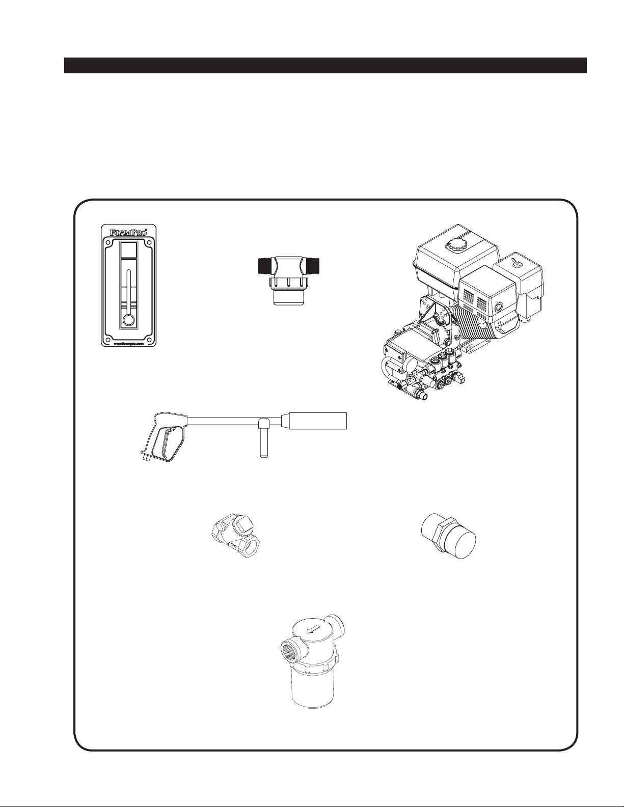
3 System Component Description
The following components are packaged with the FoamPro High Pressure System:
Control Panel
Foam Concentrate Strainer
Pump/Gas Engine Assembly
Foam Spray Gun/Wand
Thermal Relief Valve
Water Inlet Check Valve
Inlet Water Strainer

6
Installation and Operation Manual
4 Installer Supplied Parts
The FoamPro High Pressure System is provided with
the major components and accessories required for
installation. Due to differences in chassis and apparatus
configurations, the installer must provide plumbing to
satisfy individual installation requirements. The following
paragraphs list the specifications for selection of these
components. Before beginning system installation,
read this section thoroughly to make sure the proper
components are selected. For detailed system
installation instructions, refer to Sections 5, 6, and 7.
SUCTION LINES
Corrosion-resistant fittings and hoses from the foam
tank to the foam concentrate inlet of the pump must be
used. Use 5/16-inch to 3/8-inch inside diameter hose
for the foam inlet. Corrosion-resistant fittings and hoses
from the water source to the inlet of the pump must be
used. Use only 3/4-inch minimum inside diameter hose
for the water inlet. Use components that are rated for 23
in [584.2 mm] Hg vacuum and 50 psi [3 bar] pressure
or greater for all suction line inlets. The components
used must be compatible with all foam concentrates to
be used. All fittings used must be made of brass, 300
series stainless or other corrosion-resistant materials.
Before selection of components, check for compatibility
with foam concentrate. The use of clear suction hose
is recommended to allow viewing of foam and water
priming operations.
DISCHARGE LINES
Fittings and hoses from the foam solution discharge of
the pump to the foam spray nozzle must be supplied by
the installer. Hoses and fittings of 1/2-inch [12.7 mm]
minimum INSIDE diameter, rated for 1800 psi [124.1
BAR] minimum working pressure, must be supplied by
the installer. Fittings are required to be 1/2-inch male
NPT on hose ends.
The following guidelines should be followed in choosing
hose length and hose diameters.
Approximate Pressure Recommended
Hose ID Drop Per 1 ft. of Hose Max. Hose Length
1/2" 1.15 50'
5/8" .47 100'
3/4" .23 200'
1" .07 400'
Fittings and hoses must be compatible with all foam
concentrates to be used. Use fittings of brass, 300
series stainless or other corrosion-resistant material
that is compatible with foam concentrates to be used.
Thermal relief valve must be plumbed to discharge away
from operator.
CHECK VALVES
Check valves have been included with the system at the
water inlet to help prevent back flow of foam concentrate
or foam solution. The system should be disconnected
from exterior water supplies when not in use. A complete
system flush should be performed before storage to prevent
component failure due to evaporation of foam and water
within the system.
FOAM CONCENTRATE TANK
A foam concentrate tank must be supplied to suit the capacity
required for the apparatus application. The tank should
meet NFPA minimum standards for the design capacity,
including filler size, venting and drain facility. A shut-off valve
is recommended to allow cleaning of the strainer.
ELECTRICAL REQUIREMENTS
Electrical wiring must be supplied to the engine starter switch.
Use AWG No. 4 cable for power and ground connection, not
to exceed 5 ft. SEE ENGINE MANUAL for detailed electrical
hook-up specifications.
CAUTION: Always disconnect ground before electrical arc
welding on any FoamPro equipment. Failure to do so will
result in a power surge through the system that could case
irreparable damage to the electronic components.
7
Installation and Operation Manual
Turbo Stream
6 Plumbing Component Installation
5 Installation Planning
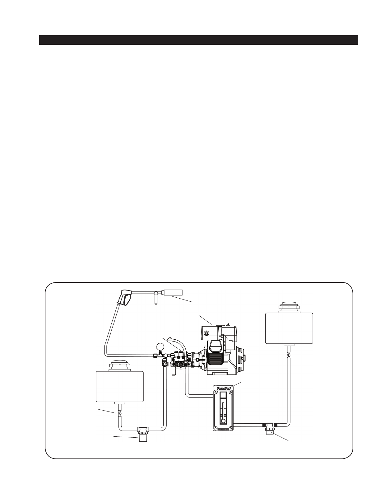
The following diagram (Figure 2) provides recommended guidelines for the location of the system components that
handle foam concentrate, water, and foam solution.
Figure 2. FoamPro High Pressure System Plumbing
Foam
Tank
Water
Tank
Water Inlet Strainer
Water Shut-Off
Valve
Foam Spray Gun
Pump/Gearbox Assy
Gas Engine
Foam Inlet Strainer
Foam
Adjustment &
Flowmeter
Because of the potential differences in apparatus
plumbing and foam system configuration, it is not
practical to depict exactly how each FoamPro unit can
best be installed onto a particular apparatus. Most of
the information contained in the following sections,
however, will apply to any situation.
It is recommended that you read the following sections
thoroughly before beginning installation of the FoamPro
system. It is also recommended that you spend time
planning and designing where and how you intend to
install this unit in the apparatus before beginning the
actual installation.
Determine the location of the components to be
installed such as: foam tank, water tank, foam system,
and display panel. Try to position the components to
minimize fittings and hose lengths. Position the system
in an accessible area.
For best performance, the foam system should be
positioned below the foam tank discharge to allow
gravity feed to the pump. The foam system will draft up
to three feet. Place the foam tank where refilling with 5
gallon [19 liter] containers and other methods is suitable
for the end user.
Determine a location for the display panel on the
unit that is visually accessible while the system is in
operation. The display panel should be located on the
same horizontal plane as the system and foam tank for
best possible performance.
Determine a safe place for the thermal relief valve drain
hose, and be sure it drains in a safe location away
from operator.

8
Installation and Operation Manual
7 Electrical Equipment Installation
8 Making Sure Everything is Working Right
PUMP/MOTOR BASE ASSEMBLY
The pump/motor base assembly must be mounted in
the horizontal position. The system can be run at 15
degrees on any plane to the horizontal and may be
run intermittently at 30 degrees to the horizontal plane.
The base of the system must be anchored to a surface
or structure that is ridged and of adequate strength to
withstand the vibration and stresses of apparatus
operation. The main pump has a water drafting capability
not to exceed six feet of vertical lift and should not be
subjected to an inlet pressure of more than 3 PSI to
ensure proper operation of the foam injection system.
The drawings on pages 14 and 15 provide the mounting
dimensions for the FoamPro High Pressure pump/motor
base assembly. Flexible hose is required to make the hose
connections to the FoamPro High Pressure System. DO
NOT hard pipe the system.
Protect the hoses and wiring to prevent chafing and
abrasion during operation of the foam system. Protect
the foam pump base unit from excessive spray
and debris. See engine manual for allowed engine
operating conditions.
LINE STRAINERS
There are two line strainers provided with the FoamPro
unit. The pump inlet line strainer has 3/4-inch NPT
female threaded ports and is to be installed on the
water inlet of the foam pump. The water supply hose
should have adequate wall stiffness to withstand
the vacuum of the pump while it is in operation [23 in.
(584 mm) Hg and 50 PSI (3 BAR)].
The second strainer has 1/2-inch NPT male and 1/4-inch
NPT female-threaded ports and is to be installed in the
foam inlet before the flow meter. The foam supply hose
should be 1/4 to 3/8- inch and able to withstand 23 in/
Hg of vacuum and 50 psi. Clear foam supply hose is
recommended so that the operator can see the flow of
foam concentrate in the hose.
NOTE: If a pressurized water flush is incorporated, the
pressure should be limited to 100 PSI (7 BAR).
CHECK VALVES
A 3/4-inch check valve is included at pump inlet. A foam
injection check valve is incorporated in the design.
FLUSHING SYSTEM
Depending on the corrosiveness of the foam concentrates
to be used, a flushing system may be required in the
foam concentrate injection system. Most Class A foam
concentrates (per NFPA 1150) are less corrosive and
therefore may not require flushing. It is important to flush
and drain the entire system before long periods of storage
to prevent component malfunction.
THERMAL RELIEF VALVE
A thermal relief valve is included with the system to prevent
pump overheating during unloading.
SYSTEM CHECK
Check fuel level and oil level per engine manual prior to
running system. Check pump and gear case oil level prior
to running system. Pump and gear case should be filled
with oil per manual instructions.
Check the function of all components before using the
system. Also check that all plumbing and components are
tight and functional.
Check to see that water supply lines, strainers and foam
tank lines are free of debris and plumbed correctly. Any
leaks in the system will cause poor system performance
and operation.
ELECTRICAL CONNECTIONS
See engine manual for detailed electrical connections only if engine is equipped with electric start.

9
Installation and Operation Manual
Turbo Stream
9 Calibration & Setup
CALIBRATION
The FoamPro High Pressure System has been
calibrated at the factory. To check calibration of the
system, the following procedure should be used:
1) Start the system. Run the engine to an RPM that
produces 8 GPM (3345 Engine RPM) of pump
water inlet flow. Tools needed for the test are
a Pitot tube or other calibrated flowmeter to test
the system inlet water flow, a graduated bucket
to remove and calibrate foam concentrate, and a
stop watch to measure volume unit/time of foam
concentrate and water flow.
2) Open the control knob of the display panel to start
foam injection, while holding the spray gun in the
on position, run the system for a few minutes. The
system will not inject foam concentrate while the
system is unloading.
3) Turn the injection control knob to the desired foam
injection calibration point. Start the stop watch
and record the necessary volumes or flow rates of
foam concentrate and water.
4) Measure the amount of foam concentrate in the
container and compare that to the calculated
amount. (Main flow rate X injection rate X minutes
flowed [8.00 GPM X 0.005 (0.5%) injection rate X
5 minutes = 0.20 gallons]).
5) CAUTION: Long periods of pump deadheading
may result in pump damage due to overheating of
water in the system. The system is equipped with
a thermal relief valve to eliminate damage to the
pump during unloading. It is recommended to idle
down the system during unloading if the system
must stay running during transportation.
6) CAUTION: System may only be calibrated with
foams with a viscosity from 60 CPS. Use of other
higher viscosity foams will create an error in
calibration and setup. Use only quality
foam concentrate.
7) Measure the amount of concentrate injected
over time and compare to the level indicated on
the display panel during this time. The output
of the FoamPro High Pressure System must be
set at a constant 8 GPM + 0.20 GPM/-0.5 GPM.
Injection rate is easily changed by turning the
foam % control knob on the display panel. The
foam percentage is indicated on the display panel
and is read using the largest diameter of the foam
percent float. Repeat at each indicated %
if desired.
8) The water inlet flow rate may be adjusted by
changing the engine RPM. Increasing the engine
RPM will increase the flow rate. Decreasing the
engine RPM will decrease the water inlet flow rate.
Varying engine RPM will change calibration settings.
NOTE: The viscosity of different foam concentrates
may have an effect on the amount of foam concentrate
that is injected into the water stream. When checking
the calibration of the system, use the foam concentrate
that will be used most frequently during normal
operations. When different viscosity foam concentrates
are used, the actual concentrate injection may vary as
much as 100%.
PRESSURE RELIEF-UNLOADER
VALVE ADJUSTMENT
The pressure relief-unloader valve is factory tested
and preset. Adjustment is only required if the
relief-unloader valve is replaced. After setting
the valve properly, no other adjustments will be
required. The following procedure is provided for
proper adjustment.
1) Start the system and run the pump to maximum
RPM with the foam spray gun in the open position.
2) Turn the adjustment nut (lower) slowly so the
pressure on the gauge is at 1450 PSI (100 BAR).
3) Turn off the foam spray gun and open it again to
ensure the pressure is the same as it was set.
4) Turn off the spray gun and shut off the engine.
Lock the adjustment nut (lower) into place with the
nut (upper).

10
Installation and Operation Manual
10 Engine Operating Instructions
PREPARATIONS BEFORE STARTING
THE SYSTEM
1) Fuel: Check fuel level in tank. Do not overfill tank.
Use fresh, clean automotive fuel. NOTE: DO NOT
FILL FUEL TANK WHEN ENGINE IS RUNNING.
2) Engine Oil: Before checking or refilling with engine
oil, make sure the engine is stopped and placed on
a stable, level surface. Use oil recommended for
ambient air temperatures at which the engine will
be running. Change oil according to manufacturer’s
recommendation. (At least once after the first 20
hours and every 100 hours thereafter.)
3) Pump Oil: Before checking or refilling with pump
oil, make sure the engine is stopped and placed on
a stable, level surface. Use oil recommended for
ambient air temperatures at which the pump will be
running. Change oil according to manufacturer’s
recommendation, using SAE 30 weight non-
detergent oil. Check oil level before running the
system using the oil level dip stick on the pump.
4) Gear Case Oil: Before checking or refilling with
gear case oil, make sure the gear case and engine
are stopped and placed on a stable level surface.
Use oil recommended for ambient air temperatures
at which the gear case will be running at. Change
oil according to manufacturer’s recommendation,
using SAE 90 weight non-detergent oil. Check oil
level before running the system using the oil level
hole on the side of the gear case.
5) Check to see that water supply lines, strainers and
foam tank lines are free of debris and plumbed
correctly. Any leaks in the system will cause poor
system performance and operation.
STARTING THE SYSTEM
IMPORTANT: Before starting engine, be sure
discharge hose is secure.
1) Turn the engine switch located by the recoil starter
to the ON position.
2) Turn the fuel cock to the ON position.
3) Push the throttle lever to a slightly open position.
4) Operation of the choke lever
a) When engine is cold:
i) In cold weather, start engine with choke in
the fully-closed position.
ii) In warm weather, start engine with choke in
half-closed position.
b) When engine is warm:
i) Start engine with choke in fully open position.
5) Open the gun by pulling the trigger. This will allow
easier starting of the engine.
6) Start the engine with electric start key or recoil starter.
OPERATION OF THE SYSTEM
1) Idle the engine for 3 to 5 minutes or until operating
temperature is achieved.
2) CAUTION: Do not run the FoamPro High Pressure
System for long periods during unloading. Long
periods of pump deadheading may result in pump
damage due to overheating of water in the system.
3) Open the throttle lever to the upper zone after
engine has reached operating temperature.
4) Once the system is primed, you will note a load on
the engine; adjust RPM to proper speed for your
pumping application.
5) Adjust the foam concentrate injection percentage
with the display panel to the desired percentage
while the system is running at full capacity (8 GPM).
STOPPING THE SYSTEM
1) Stop pump for a short time:
a) Run throttle all the way down (fully to the right).
b) Turn engine switch to OFF position.
c) Turn the fuel cock to the OFF position. This
valve should be closed for transporting the
unit also.
2) Stopping pump for storage:
a) Turn fuel cock to OFF position instead of
turning the engine off.
b) Let the engine idle for 2 to 3 minutes until fuel
in the carburetor is depleted and engine stops.
c) Drain the pump and flush pump after use.
d) Drain all fuel from engine.
e) Store system in clean, dry environment.

11
Installation and Operation Manual
Turbo Stream
11 Maintenance
12 Troubleshooting
1. Daily: Inspect wiring, hoses, pump, gear case,
engine and connectors for tightness, corrosion,
leaks and/or damage.
2. Daily: Check hydraulic/engine oil level and refill
as necessary.
3. Monthly: Remove and clean the foam and pump
inlet strainer screens. Flush as required.
4. Monthly: Check pump gear case oil level and refill
as necessary.
5. Monthly: Check gear case oil level and refill
as necessary.
6. Monthly: Change engine oil every month or every
100 hours, whichever comes first. First oil change is
to be done at 20 hours.
7. Annually: Drain the pump oil and refill pump gear
case with SAE 30 weight non-detergent oil. Check for
foreign materials in the drained oil (water or debris).
8. Annually: Drain the gearbox oil and refill gearbox
with SAE 90 weight gear lube. Check for foreign
materials in drained oil.
Note: Water quality, flushing and storage
techniques, environment and usage may have an
effect on your maintenance schedule. To ensure
equipment longevity, it is recommended to adjust
your schedule accordingly.
Caution: Release all pressure and drain all
concentrate and water from the system before
servicing any of its components.
The FoamPro Turbo Stream system is designed to be easy to diagnose and service. There are several major
components (see Figure 2). Servicing the system involves isolation of the failed component and replacing it.
Following the trouble-shooting guide will allow quick diagnosis of the problem and the corrective action to take.
Symptom Probable Cause(s) Corrective Action
Pump runs but produces no flow. Pump is not primed. Pull trigger on foam sprayer gun while priming pump.
Pump loses prime, Air leak in suction hose or inlet fittings. Remove suction hose and test for leaks by pressurizing hose
chattering noise, pressure fluctuates. with water. Make sure thread sealant has been used on all
fittings.
Suction line is blocked, collapsed or Remove suction line and inspect it for a loose line or debris
too small. lodged in hose. Avoid all unnecessary bends. Do not kink hose.
Clogged suction strainer. Clean strainer.
Foam pump capacity below rating. Net Positive Suction Head required. If foam does not flow freely, modification of piping and pump
location is required.
Engine RPM Check engine RPM
Engine does not run or runs poorly. See engine manual.
12
Installation and Operation Manual
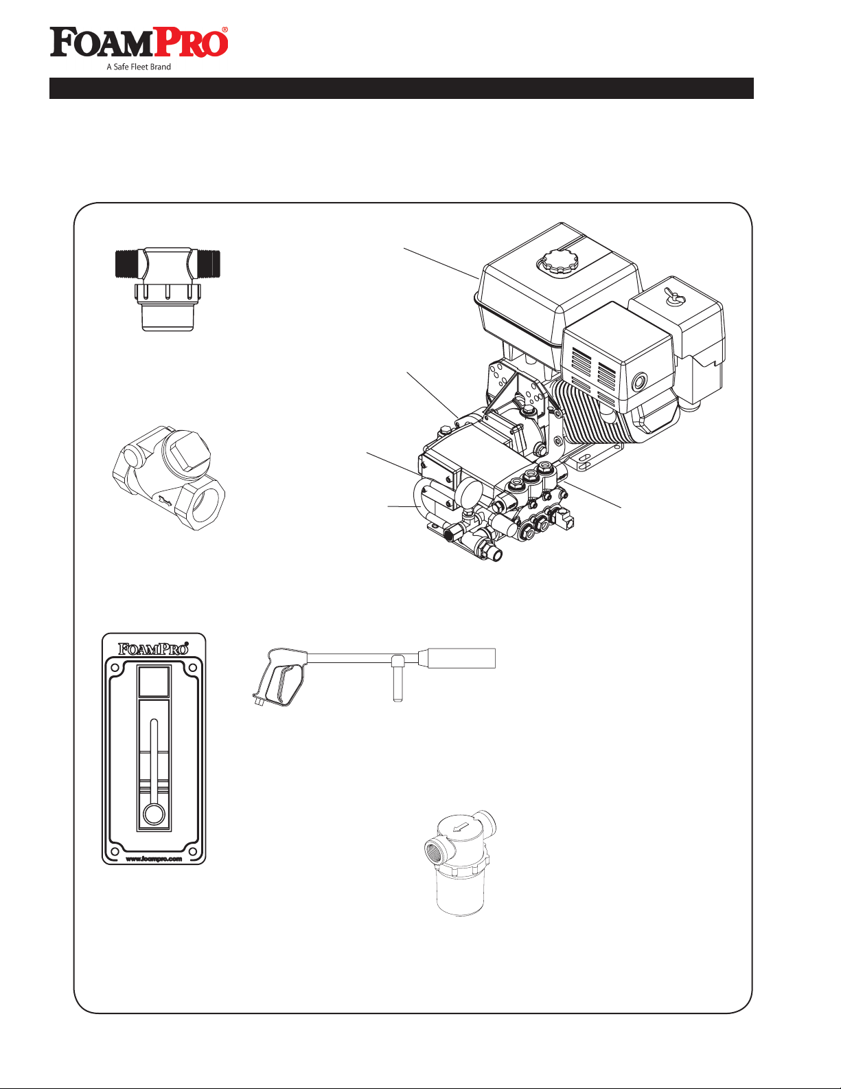
13 Parts Identification
2414B-G1P
Pump/Gearbox Assy.
2541-0049
PowerProTM Engine
2541-0057
Honda Engine
3312-0005
Thermal Relief Valve
2640-0004
Pressure Gauge
6032-0078
Control Panel
3320-0063
Inlet Check Valve
3350-0085
Foam Inlet Strainer
3350-0044
Water Inlet Strainer
3381-0045
Gun/Wand Assembly
with Low Pressure 3385-4500 Nozzle (approx. 400 PSI)
Nozzles
High Pressure 3385-2300 (1450 PSI)
Medium Pressure 3385-3000 (750 PSI)
2900-0049
Bypass Hose
13
Installation and Operation Manual
Turbo Stream
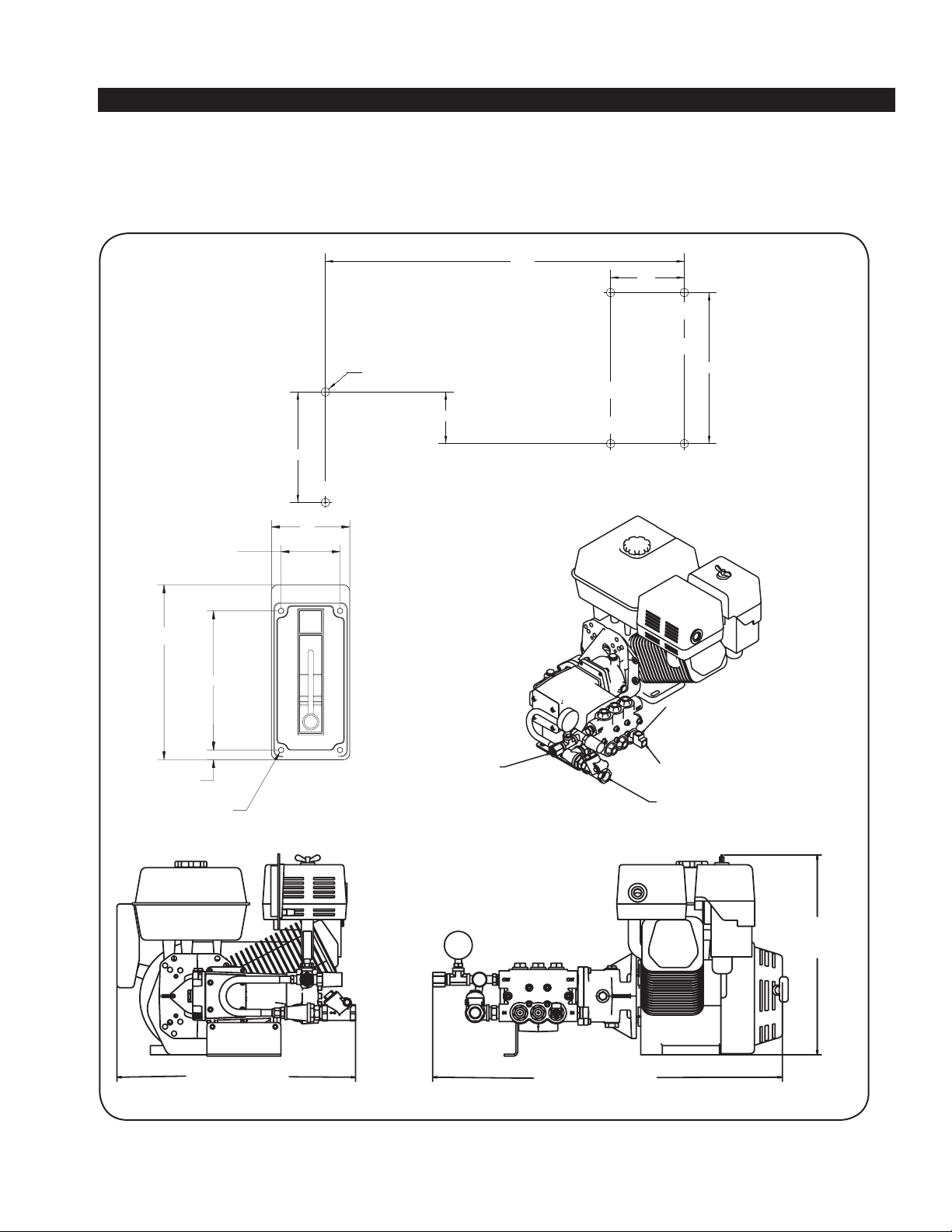
21.44 31.31
17.94
Pulse Hose Connection
Foam Concentrate Inlet
3/8-18 NPT
Water Inlet Port
3/4-14 NPT
Solution Outlet
1/2-14 NPT
6.69
5.31
.38
.22 Dia (4)
2.25
3
14 Installation Drawings
.44 Dia (6 Holes)
5.62
2.63
7.68
3.75
18.25

14
Installation and Operation Manual
NOTES

15
Installation and Operation Manual
Turbo Stream
NOTES

Installation and Operation Manual
26 Southern Blvd. • Nesconset, NY 11767 USA
Phone 800-645-0074 • FAX 816-892-3178
www.fireresearch.com
26 Southern Blvd. • Nesconset, NY 11767 USA
Phone 800-533-9511 • FAX 816-892-3178
www.foampro.com
15 Limited Warranty
Fire Research Corp. (FRC), as supplier of FoamPro, warrants to the original purchaser, each new pump, system or other product of its
own manufacture, for a period of two years from the date of shipment from the factory, to be free from defects in material and
workmanship under normal use and service. “Normal use and service” means not in excess of recommended maximum speeds,
pressures, and temperatures, or handling fluids not compatible with components materials, as noted in applicable FoamPro
product catalogs, technical literature, and instructions. This warranty shall not apply to any pump, system or other product which
shall have been repaired or altered to adversely affect the performance or reliability of the pump, system or other product.
Neither this warranty nor any implied warranty apply to damage or harm caused by any or all of the following: (1) Freight damage;
(2) Freezing damage; (3) Damage caused by parts and/or accessories or components not obtained from or approved by FRC; (4)
ANY CONSEQUENTIAL OR INCIDENTAL DAMAGES, OTHER THAN INJURY TO THE PERSON, ARISING FROM THE USE
OF ANY PUMP OR OTHER PRODUCT MANUFACTURED BY FRC EXCEPT in states that do not allow the exclusion or limitation
of incidental or consequential damages; (5) Damage due to misapplication and/or misuse; (6) Normal wear of moving parts or
components affected by moving parts.
The liability of FRC under the foregoing warranty is limited to the repair or replacement at FRC's option without charge for labor
or materials of any parts upon return of the entire pump, system or other product or of the particular part to the FRC factory within
the warranty period, at the sole expense of the purchaser, which part shall upon examination appear to FRC’s satisfaction to have
been defective in material and workmanship. The liability of FRC under any theory of recovery (except any express warranty where
the remedy is set forth in the above paragraph) for loss, harm or damage, shall be limited to the lesser of the actual loss, harm or
damage or the purchase price of the involved pump, system or other product when sold by FRC to its customer.
FRC expressly warrants its pumps and other products as above stated. THERE ARE NO OTHER EXPRESS WARRANTIES. ANY
IMPLIED WARRANTIES, INCLUDING IMPLIED WARRANTY OF MERCHANTABILITY OR OF FITNESS FOR A PARTICULAR
PURPOSE, ARE LIMITED IN DURATION TO TWO YEARS FROM THE DATE OF PURCHASE BY THE ORIGINAL
PURCHASER EXCEPT in states that do not allow time limitations on implied warranties. THERE IS NO IMPLIED WARRANTY OF
FITNESS FOR A PARTICULAR PURPOSE OR MERCHANTABILITY WHEN THIS PRODUCT IS PUT TO RENTAL USE.
No person including any dealer or representative of FoamPro is authorized to make any representation or warranty concerning
FRC’s FoamPro products on behalf of FRC, or to assume for FRC the obligations contained in this warranty. FRC reserves the
right to make changes in design and other changes and improvements upon its products without imposing any obligations upon
itself to install the same, upon its existing products then in process or manufacture.
This warranty gives you specific legal rights, and you may also have other rights which vary from state to state.
IMPORTANT NOTICE
It is imperative to package all FoamPro components properly, before shipment (with Return Goods Authorization attached) back
to FRC. The FoamPro contains electronic components that may receive damage from improper shipping procedures! All FoamPro
components shipped back to FRC will pass through Quality Control Inspection, and will be photographed after the box is opened.
Any shipping damage, such as superficial scratches, nicks, etc., to the unit makes it unusable (even after the internal warranty
problem is repaired) and thus must be refinished to “like-new” condition during the warranty process. You are responsible for any
physical damage occurring to FoamPro components at your facility and during shipment back to FRC.
Package the FoamPro, complete with all the recommended parts the Customer Service representative requires (i.e., Digital
Display control with all premolded wire cables etc.) in its original carton with the Styrofoam and other packaging materials, as it
was received at your facility. FRC appreciates your attention in this matter, as we feel it will help us to serve you in a better fashion,
while keeping the cost of the FoamPro product competitive. Thank you.
Other manuals for Turbo Stream S108-4008
1
This manual suits for next models
2
Table of contents
Popular Paint Sprayer manuals by other brands


Clas Ohlson
Clas Ohlson SJ-108 instruction manual

National Garden Wholesale
National Garden Wholesale EZ Sprayer user manual

Gilson
Gilson SS-8R operating manual

Ningbo Dino-power Machinery
Ningbo Dino-power Machinery DP6388B owner's manual

Hozelock
Hozelock PortaShower Instructions & warnings

OHAUS
OHAUS SHRC0719DG instruction manual

Reflex
Reflex Servitec Mini Original operating manual

Annovi Reverberi
Annovi Reverberi AR Spray 16 Original instructions

Husqvarna
Husqvarna BP4E Owner's/operator's manual

WAGNER
WAGNER Paint Crew 770 owner's manual

Jula
Jula 082-203 operating instructions

Milwaukee
Milwaukee HEAVY DUTY M12 BHCS3L Original instructions