Focus Bikes DROPPER POST Manual

DROPPER POST
Version 1 | 24.02.2021
EN INFORMATION SHEET
ADJUSTABLE SEATPOST
Subject to misprints, errors and technical alterations.
1973K0022012
www.focus-bikes.com
FOCUS BIKES
Rotenwaldstraße 158
70197 Stuttgart
Germany
Legal Base:
Derby Cycle Werke GmbH
Siemensstraße 1-3
49661 Cloppenburg
Germany
Telefon: +49 (0)4471 966-401745
Telefax: +49 (0)4471.966-210
E-Mail: info@focus-bikes.com

ADJUSTABLE SEATPOST
With a low seating position, you have more control over your bike in
challenging situations. If your bike is equipped with a dropper post, you
can adjust the height of the seatpost while riding. It is operated via a
remote lever on the handlebar.
Pressing the lever will raise or lower the dropper post. As soon as you
release the lever, the dropper post locks in position. If you have any
questions about the use and adjustment of the adjustable seatpost or if
you experience any problems, please contact your dealer.
WARNING
SERIOUS FALLS DUE TO A KINKED OR BROKEN SEATPOST.
• Use the proper torque wrench for the tightening range when making
adjustments.
• Ensure all quick-release systems are correctly tightened before you
ride. Check all quick releases before using.
• Only use your bike for its intended purpose. This may not include going
downhill.
• Check the seatpost regularly for damage and a secure fit, especially
after every fall. Do not ride it again if there is any damage. Replace the
seatpost.
• Replace the seatpost after 14,000 kilometres regardless of the
condition of the material or whether or not defects or damage are
noticeable.
• If you do not replace the seatpost in due time, it can break and cause
serious falls.
SAFETY INFORMATION OVERVIEW
1 Seat clamp
2 Upper seatpost
3 Lower seatpost
4 Release mechanism
5 Cable
6 Remote lever
7 M4 screw (1.2-1.6 Nm)
8 Tension adjuster
9 Set screw (3-4Nm)
10 M6 screw (8-10 Nm)
1
2
3 5
9
10
10
67 8
4
WARNING
SEVERE FALLS DUE TO A BLOCKED REAR WHEEL
• Before your first ride, check whether the rear wheel is blocked when the
seat post is lowered. If the saddle touches the rear wheel in its lowest po-
sition, you need to reduce the insertion depth of the seat post. Make sure,
however, that the seat post is inserted at least 100 mm in the seat tube.
fork in such a way that it does not open unintentionally. Please also note
the description in the general operating instructions. Do not leave lever
protruding to the side. The lever must rest against the frame or fork in
such a way that it does not open unintentionally. Please also note the
description in the general operating instructions.
3. b) Tighten the Allen screw(s) on the seat tube clamp with the torque
specified on the component. If no torque is specified, tighten the screws
to 6 Nm.
4. Check the tightness of the saddle and seatpost by attempting to twist
them.
1. Loosen both M6 screws 10 by turning anticlockwise. Do not loosen
the screws by more than two to three turns, otherwise the entire
mechanism may fall apart.
2. The saddle should be level with the ground. Check this with a spirit
level.
3. Turn both M6 screws 10 into the nuts clockwise. Tighten to 8 to 10
Nm.
4. Ensure that the newly-tightened saddle does not tip; test it by press-
ing down on the front and back alternately.
INSTALL 6REMOTE LEVER
1. Loosen the M4 screw 7on the remote lever 6by turning it two to
three turns anticlockwise.
2. Move the lever to the desired position.
3. Tighten the M4 screw 7on the lever 6to a maximum of 1.6 Nm.
REDUCE CABLE TENSION
If the lever is difficult to press, it may help to reduce the cable tension.
1. Turn the tension adjuster 8one to two turns anticlockwise to re-
duce tension.
WARNING
SERIOUS FALLS DUE TO A KINKED
OR BROKEN SEATPOST.
• The seatpost must be at least 100 mm deep in the seat tube. The
minimum insertion depth of 100 mm also applies if the specifications
on the seatpost itself are different.
WARNING
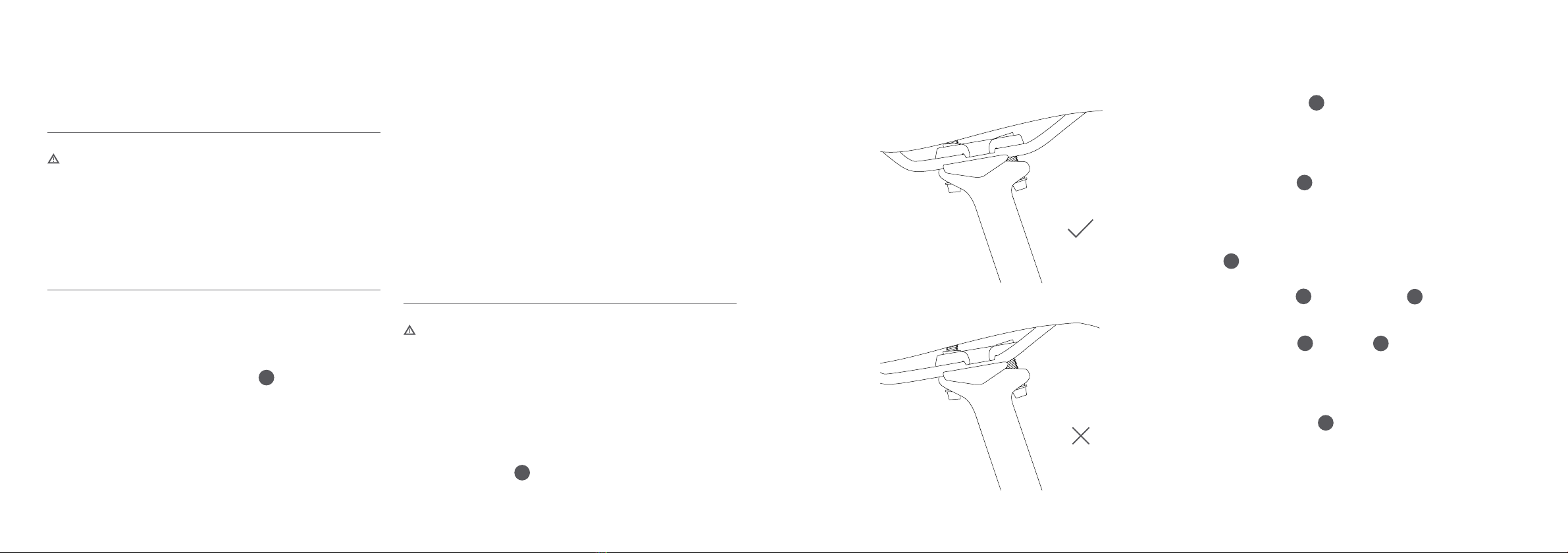
SEVERE FALLS DUE TO BROKEN SADDLE CLAMPS.
• Never clamp the saddle in the curve of the saddle rail; always do it in
the straight section. Only shift the saddle within the straight section.
SEVERE FALLS DUE TO KINKED SADDLE.
• Screw the M6 screws completely into the nuts. Otherwise they can
tear off.
1. Loosen the quick release or the Allen screw(s) on the seat tube clamp
to move the seatpost.
2. Adjust the seatpost to the desired height. Make sure to observe the
minimum insertion depth of 100 mm. If the seatpost cannot be pulled
out of the seat tube, you need to slide the 5cable into the frame a
little via the headtube.
3. a) Close the quick release by swinging the lever 180°. It should now read
CLOSE. Halfway through the action of closing the lever, the movement
should be very easy. The required leverage should increase after that
point and the lever should be difficult to close at the end. In the end
position, the lever must be perpendicular to the quick release axis. It
must not stick out to the side. The lever must rest against the frame or
ADJUST THE SADDLE HEIGHT
ADJUST SADDLE POSITION
CORRECT
WRONG
10

INCREASE CABLE TENSION
If the lever moves too easily and the device is not working properly, it
may help to increase the tension:
1. Turn the tension adjuster 8clockwise to increase tension.
CLEANING
Never clean your bike with a pressure washer. Only use a soft cloth
slightly moistened with water to clean the seatpost. Do not use oily or
aggressive cleaning agents.
WWW.FOCUS-BIKES.COM
Other Focus Bikes Bicycle Accessories manuals


