manuals.online logo
Brands
  1. Home
  2. •
  3. Brands
  4. •
  5. Follett
  6. •
  7. Water Dispenser
  8. •
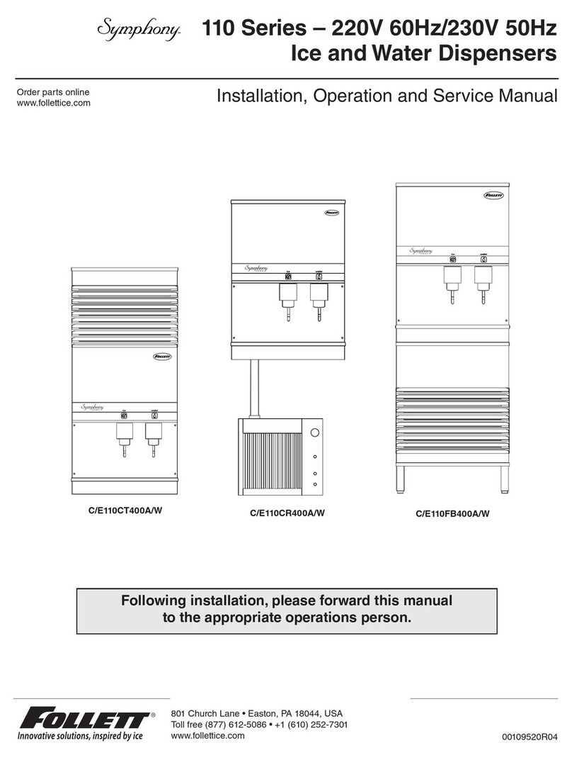
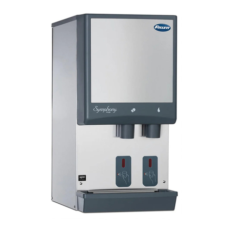
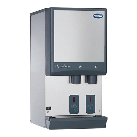
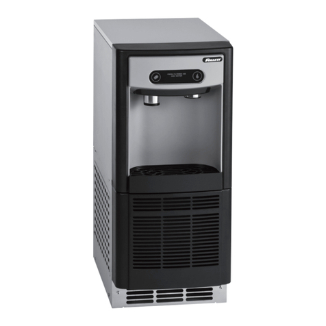
  9. Follett Chewblet 7 Series User manual

Follett Chewblet 7 Series User manual

Other manuals for Chewblet 7 Series

1

This manual suits for next models

5

Other Follett Water Dispenser manuals

Follett 7UC100A Setup guide

Follett

Follett 7UC100A Setup guide

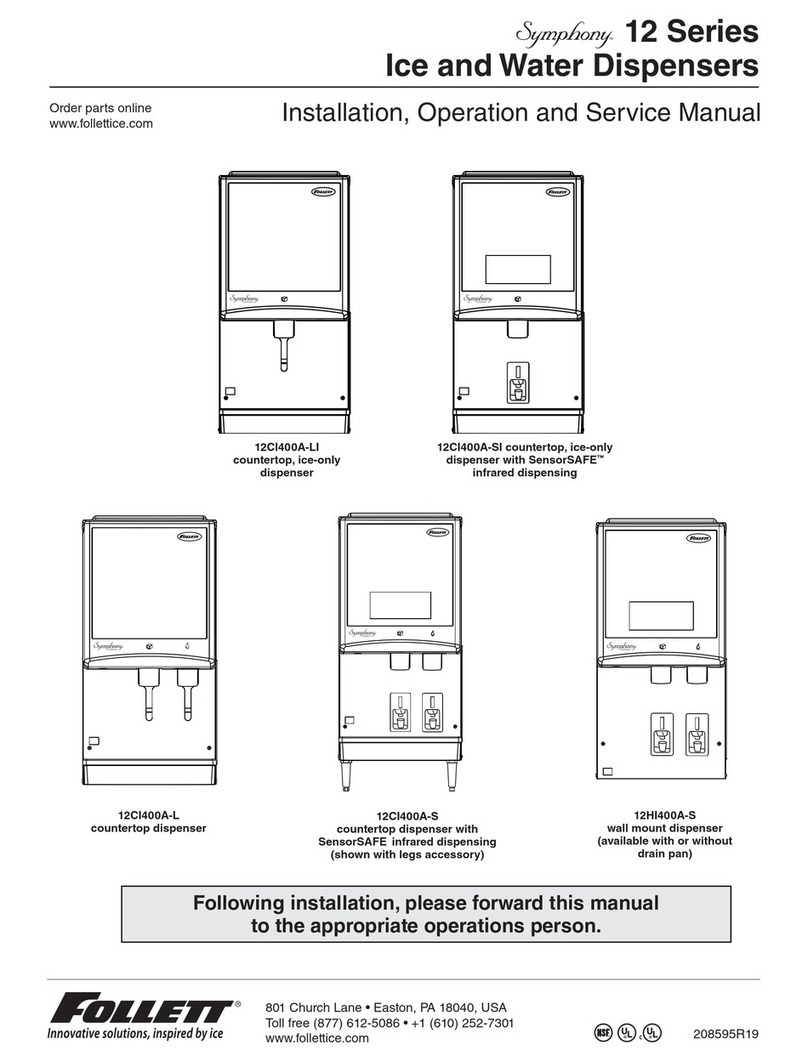
Follett C/E12CI400A Manual

Follett

Follett C/E12CI400A Manual

Follett Symphony E12CI425A Operation manual

Follett

Follett Symphony E12CI425A Operation manual

Follett 50HI425A Setup guide

Follett

Follett 50HI425A Setup guide

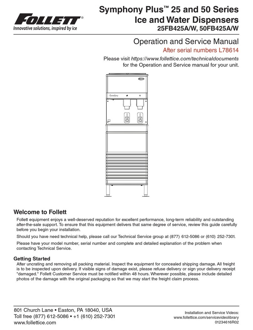
Follett L78614 Setup guide

Follett

Follett L78614 Setup guide

Follett Symphony Plus C/E12CI425A-LI Operation manual

Follett

Follett Symphony Plus C/E12CI425A-LI Operation manual

Follett 7UC100A Setup guide

Follett

Follett 7UC100A Setup guide

Follett C25T5A/W User manual

Follett

Follett C25T5A/W User manual

Follett Symphony 01089580 User manual

Follett

Follett Symphony 01089580 User manual

Follett 12 Setup guide

Follett

Follett 12 Setup guide

Follett E7CI100A Setup guide

Follett

Follett E7CI100A Setup guide

Follett 25CI400A Setup guide

Follett

Follett 25CI400A Setup guide

Follett 25FB425A Operation manual

Follett

Follett 25FB425A Operation manual

Follett 25 Manual

Follett

Follett 25 Manual

Follett 7CI100A Setup guide

Follett

Follett 7CI100A Setup guide

Follett Symphony Plus 50 Series Setup guide

Follett

Follett Symphony Plus 50 Series Setup guide

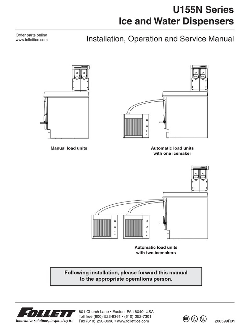
Follett U155N Series Setup guide

Follett

Follett U155N Series Setup guide

Follett EVU155NW Setup guide

Follett

Follett EVU155NW Setup guide

Follett 25CI400A Setup guide

Follett

Follett 25CI400A Setup guide

Follett Symphony Plus 25 series Operation manual

Follett

Follett Symphony Plus 25 series Operation manual

Follett C/E25CI425A Setup guide

Follett

Follett C/E25CI425A Setup guide

Follett 25CI425A/W Setup guide

Follett

Follett 25CI425A/W Setup guide

Follett 7CI100A Setup guide

Follett

Follett 7CI100A Setup guide

Follett 12CI425A-LI Operation manual

Follett

Follett 12CI425A-LI Operation manual

Popular Water Dispenser manuals by other brands

IBC Water AST0715MP-960 Installation & operating instructions

IBC Water

IBC Water AST0715MP-960 Installation & operating instructions

Lancaster Water Treatment X FACTOR LX15 Series Installation, operating and service manual

Lancaster Water Treatment

Lancaster Water Treatment X FACTOR LX15 Series Installation, operating and service manual

Elkay EMABF8 Series Installation & use manual

Elkay

Elkay EMABF8 Series Installation & use manual

Oasis Osmosis Home installation manual

Oasis

Oasis Osmosis Home installation manual

Monarch Water ULTIMATE MINI AQUA HE install guide

Monarch Water

Monarch Water ULTIMATE MINI AQUA HE install guide

Haier HLM-109B instruction manual

Haier

Haier HLM-109B instruction manual

GE GXOF18G Owner's manual and installation instructions

GE

GE GXOF18G Owner's manual and installation instructions

Kenmore 625.385560 UltraFilter 650 owner's manual

Kenmore

Kenmore 625.385560 UltraFilter 650 owner's manual

Aries Hydra DI Operation & maintenance manual

Aries

Aries Hydra DI Operation & maintenance manual

Avanti WD31EC instruction manual

Avanti

Avanti WD31EC instruction manual

GE GNCF02H owner's manual

GE

GE GNCF02H owner's manual

Avanti WD360 instruction manual

Avanti

Avanti WD360 instruction manual

ProFlo PFB Series Installation & operation manual

ProFlo

ProFlo PFB Series Installation & operation manual

Frakco Travelsoft RV 2400HD Operation instructions

Frakco

Frakco Travelsoft RV 2400HD Operation instructions

Aqua Essentials Borg & Overström B4 user guide

Aqua Essentials

Aqua Essentials Borg & Overström B4 user guide

KENT 11063 Instruction handbook

KENT

KENT 11063 Instruction handbook

Calmat Plus user manual

Calmat

Calmat Plus user manual

Igloo MWC529 instruction manual

Igloo

Igloo MWC529 instruction manual

manuals.online logo
manuals.online logoBrands
  • About & Mission
  • Contact us
  • Privacy Policy
  • Terms and Conditions

Copyright 2025 Manuals.Online. All Rights Reserved.

Installation and Service Videos:
www.follettice.com/servicevideolibrary
01234673R01
801 Church Lane • Easton, PA 18040, USA
Toll free (877) 612-5086 • +1 (610) 252-7301
www.follettice.com
Installation Guide
115 V, 230 V, 220 V
Please visit https://www.follettice.com/technicaldocuments
for the Operation and Service manual for your unit.
7 and 15 Series
Ice and Water Dispenser
with Chewblet®Ice Machine
CI100A, FS100A, UC100A, UD100A
Welcome to Follett
Follett equipment enjoys a well-deserved reputation for excellent performance, long-term reliability and outstanding
after-the-sale support. To ensure that this equipment delivers that same degree of service, review this guide
carefully before you begin your installation.
Should you need technical help, please call our Technical Service group at (877) 612-5086 or (610) 252-7301.
Please have your model number, serial number and complete and detailed explanation of the problem when
contacting Technical Service.
Getting Started
After uncrating and removing all packing material, inspect the equipment for concealed shipping damage. All freight
is to be inspected upon delivery. If visible signs of damage exist, please refuse delivery or sign your delivery receipt
"damaged." Follett Customer Service must be notied within 48 hours. Wherever possible, please include detailed
photos of the damage with the original packaging so that we may start the freight claim process.
2 Dispenser and Ice Machine - 115 V, 230 V, 220 V
CAUTION!
§Do not tilt unit further than 30° off vertical during uncrating or installation.
§Dispenser bin area contains mechanical, moving parts. Keep hands and arms clear of this area at all times. If
access to this area is required, power to unit must be disconnected rst.
§This appliance is not suitable for installation in an area where a water jet could be used.
§This appliance must not be cleaned by a water jet.
§User maintence should not be done by children.
§Follett recommends a Follett water lter system be installed in the ice machine inlet water line (standard
capacity #00130229, high capacity #00978957, carbonless high capacity #01050442).
§Prior to operation clean the dispenser in accordance with instructions found in this manual.
§Do not block air intake or exhaust.
§This appliance should be permanently connected by a qualied person in accordance with application codes.
§A qualied person shall provide a readily accessible disconnect device incorporated into the xed wiring.
§If the supply cord is damaged, it must be replaced by the manufacturer, its service agent or similarly qualied
persons in order to avoid a hazard.
§This appliance can be used by children aged 8 years and above and persons with reduced physical, sensory,
or mental capabilities, or lack of experience and knowledge if they have been given supervision or instruction
concerning use of the appliance in a safe way and understand the hazards involved. Children should be
supervised to ensure that they do not play with the appliance.
§This appliance is designed for commercial use.
§WARNING! To avoid a hazard due to instability of the appliance, it must be xed in accordance with the
instructions.
§Warranty does not cover exterior or outside installations.
§To reduce risk of shock, disconnect power before servicing.
§Connect to potable water supply only.
§Ice is slippery. Maintain counters and oors around dispenser in a clean and ice-free condition.
§Ice is food. Follow recommended cleaning instructions to maintain cleanliness of delivered ice.
Dispenser and Ice Machine - 115 V, 230 V, 220 V 3
Before You Begin
If needed, the serial number of your dispenser can be found by removing the drip tray ❶and locating the serial
number label ❷. A QR Code is located on the right hand side of the drip tray ❸. This code allows you to access
manuals, technical bulletins, and on-line training related to the 7 Series and 15 Series dispensers.
2
1
3
www.follettice.com/7SeriesTechDocs
01105196R00
Scan to access technical documentation
4 Dispenser and Ice Machine - 115 V, 230 V, 220 V
Specications
Dimensions
Width Depth Height Unit Shipping Weight
7CI100A 14.50" (40 cm) 22.12" (56.2 cm) 17.50" (44.5 cm) 90 lb (41 kg)
7FS100A 14.50" (40 cm) 22.12" (56.2 cm) 41.88" (106.4 cm) 120 lb (54 kg)
15CI100A 14.50" (40 cm) 23.50" (59.7 cm) 22.50" (57.2 cm) 100 lb (45 kg)
15FS100A 14.50" (40 cm) 23.50" (59.7 cm) 46.75" (118.7 cm) 130 lb (60 kg)
7UC100A 14.55" (37 cm) 22.05" (56 cm) 33.50" (85.1 cm) 100 lb (45 kg)
7UD100A 14.55" (37 cm) 22.05" (56 cm) 31.50" (80 cm) 100 lb (45 kg)
Ambient Information
CAUTION!
The 7 and 15 Series are for indoor use only. Designed for commercial use.
Follett is not able to provide in-house services for residential installations.
Maximum* Minimum*
Air Temperature†100 F (38 C) 50 F (10 C)
Water Temperature 90 F (32.2 C) 40 F (4.5 C)
Water Pressure 70 psi (483 kpa) 10 psi (69 kpa)
Relative Humidity 55% at 78 F (25.5 C)
* Use outside of these limitations is misuse and will void warranty.
† Best performance is achieved between 80 F (27 C) and 50 F (10 C).
Plumbing
§Water Inlet: 1/4" MPT or John Guest push-in tting
§Optional Drain Accessory Kit (item# 00956375 or 00981977): 1/2" ID tubing
§Water shut-off recommended within 5 ft (1.5 m) of dispenser
Dispenser and Ice Machine - 115 V, 230 V, 220 V 5
Water
WARNING!
Connect to potable water supply only.
§Water Mineral Content:
– TDS: greater than 5 ppm (mg/l) but less than 400 ppm (mg/l)
– Hardness: Less than 200 mg/l (12 gpg)
§Not recommended for use with softened water
§Ingress Protection (IP) rating: IPX0 (no protection)
Clearances
§CI/FS Models: 3" (7.6 cm) behind and on each side of dispenser for electrical and connection and
ventilation
§UD/UC Models: 3" (7.6 cm) behind dispenser for electrical and optional drain connection. 6" (153 mm) in
front of dispenser for ventilation.
Electrical
115 V
§115 V, 60 Hz, 1 phase, 5A, maximum fuse 15A
§Connect to dedicated 15A circuit, fuse or breaker
§Must be grounded - requires 3-prong outlet. Do not remove ground.
230 V and 220 V
§230 V, 50 Hz, 1 phase, 5.5A or 220 V, 60 Hz, 1 phase, 5.5A
§Connect to a dedicated circuit
§Equipment ground required
§Cord provided on ice machine
§Replacement cord instructions, type IEC 60320-C13 attachment. If the supply cord is damaged, it must be
replaced by a special cord or assembly available from the manufacturer or its service agent.
Refrigeration
WARNING!
Do not damage the refrigerant circuit. Refrigerant can cause personal injury and/or damage dispenser.
§Refrigerant
– 115 V: R134a – 5.0 ounces (142 grams)
– 230 V/220V: R134a – 7.2 ounces (204 grams)
Heat Rejection
§1700 BTU/hr (498 W)
6 Dispenser and Ice Machine - 115 V, 230 V, 220 V
7 Series Detailed Drawing - CI and FS Models
G
L2
L1
G
L2
L1
water inlet:
1/4" MPT
or John Guest
push-in fitting
Freestanding models
Countertop models
14.5" (36.8 cm)
17.50"
(44.5 cm)
NEMA 5-15
right angle
(115 V only)
power cord
17.50"
(44.5 cm)
14.5" (36.8 cm)
14.50" (36.8 cm)
14.50" (36.8 cm)
22.12" (56.2 cm)
22.12" (56.2 cm)
24.38"
(61.9 cm)
17.50"
(44.5 cm)
17.50"
(44.5 cm)
2.50"
(6.4 cm)
water inlet:
1/4" MPT
or John Guest
push-in fitting
6.88"
(17.5 cm)
6.75"
(17.2 cm)
3.00"
(7.6 cm)
NEMA 5-15
right angle
(115 V only)
power cord
2.50"
(6.4 cm)
6.88"
(17.5 cm)
6.75"
(17.2 cm)
3.00"
(7.6 cm)
Dispenser and Ice Machine - 115 V, 230 V, 220 V 7
15 Series Detailed Drawing - CI and FS Models
G
L2
L1
Freestanding models
Countertop models
14.50" (36.8 cm)
22.50"
(57.2 cm)
14.50" (36.8 cm)
14.50" (36.8 cm)
22.12" (56.2 cm)
22.12" (56.2 cm)
22.38"
(56.8 cm)
24.38"
(61.9 cm)
water inlet:
1/4" MPT
or John Guest
push-in fitting
2.50"
(6.4 cm)
6.75"
(17.2 cm)
22.50"
(57.2 cm)
6.88"
(17.5 cm)
3.00"
(7.6 cm)
NEMA 5-15
right angle
(115 V only)
power cord
23.50" (59.7 cm)
46.75"
(118.7 cm)
23.50" (59.7 cm)
G
L2
L1
14.50" (36.8 cm)
water inlet:
1/4" MPT
or John Guest
push-in fitting
2.50"
(6.4 cm)
6.75"
(17.2 cm)
22.50"
(57.2 cm)
6.88"
(17.5 cm)
3.00"
(7.6 cm)
NEMA 5-15
right angle
(115 V only)
power cord
8 Dispenser and Ice Machine - 115 V, 230 V, 220 V
7 Series Detailed Drawing - UC and UD Models
A
A
C
B
7UC100A 7UD100A (ADA)
A
B
C
G
L2
L1
water inlet: 1/4" MPT
or John Guest
push-in fitting
SIDE VIEW
BACK VIEW
FRONT VIEW
Dimension
33.50" (85.1 cm)
22.76" (57.8 cm)
22.69" (57.6 cm)
31.50" (80 cm)
20.76" (52.7 cm)
20.69" (52.6 cm)
14.55" (37 cm) 22.05" (56 cm)
14.55" (37 cm)
2.40"
(6.1 cm) 2.98"
(7.6 cm)
3.81"
(9.7 cm)
4.00"
(10.2 cm)
NEMA 5-15
right angle
power cord
Dispenser and Ice Machine - 115 V, 230 V, 220 V 9
Installation
CAUTION!
No service or maintenance should be performed until the technician
has thoroughly read this service manual. Except for routine cleaning
and sanitizing, only qualied technicians should attempt to service
or maintain this equipment.
Countertop Installation
The 7 Series countertop model is designed to t on counters underneath
standard mounted cabinets, this does not apply to 15 Series models.
1. A clearance of at least 3" (7.6 cm) is required behind and on each
side of the dispenser for electrical connection and ventilation
(Fig.1).
2. Rough-in the electrical service and water line.
§Water: supply line (with shut-off valve) connects to the dispenser's
1/4" MPT inlet or John Guest push-in tting.
NOTICE!
If installing optional Drip Tray Drain Kit or Leg Accessory,
complete those steps before proceeding.
Fig. 1
CAUTION!
Use caution when tipping the dispenser during leg installation. Do
not lay unit on back or side. DO NOT EXCEED 30° angle. Tipping
more than 30° can result in compressor malfunction.
3. If installing optional 4" Leg Accessory (item# 00956300), place a
5" (12.7 cm) spacer underneath the dispenser to ease installation.
4. Remove four plastic, thread-protecting plugs from bottom of
dispenser.
5. Screw each leg into chassis (Fig. 3).
6. Complete Potable Water Connection before proceeding.
Fig. 2
countertop models
minimum 3" (7.6 cm)
clearance required
spacer
12.7 cm (5")
min.
10 Dispenser and Ice Machine - 115 V, 230 V, 220 V
Freestanding Installation
1. A clearance of at least 3" (7.6 cm) is required behind and on each
side of the dispenser for electrical connection and ventilation
(Fig.4).
2. Rough-in the electrical service and water line.
§Electrical: 115 V, single phase, 15A receptacle required. The dispenser
has an integral 8 ft (2.4 m) cord and plug.
§Water: supply line (with shut-off valve) connects to the dispenser's
1/4" MPT inlet or John Guest push-in tting.
Fig. 3
3. If installing optional 6" Leg Accessory (item# 00956318), tilt or lay
base stand on side and screw each leg into stand (Fig.8).
Fig. 4
4. Remove four plastic, thread-protecting plugs from bottom of
dispenser.
5. Attach dispenser to base stand with supplied hardware (Fig. 5).
NOTICE!
If installing optional Drip Tray Drain Kit, refer to instructions
included with the Drip Tray Drain Kit.
Fig. 5
freestanding models
minimum 3" (7.6 cm)
clearance required
X4