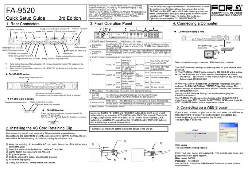
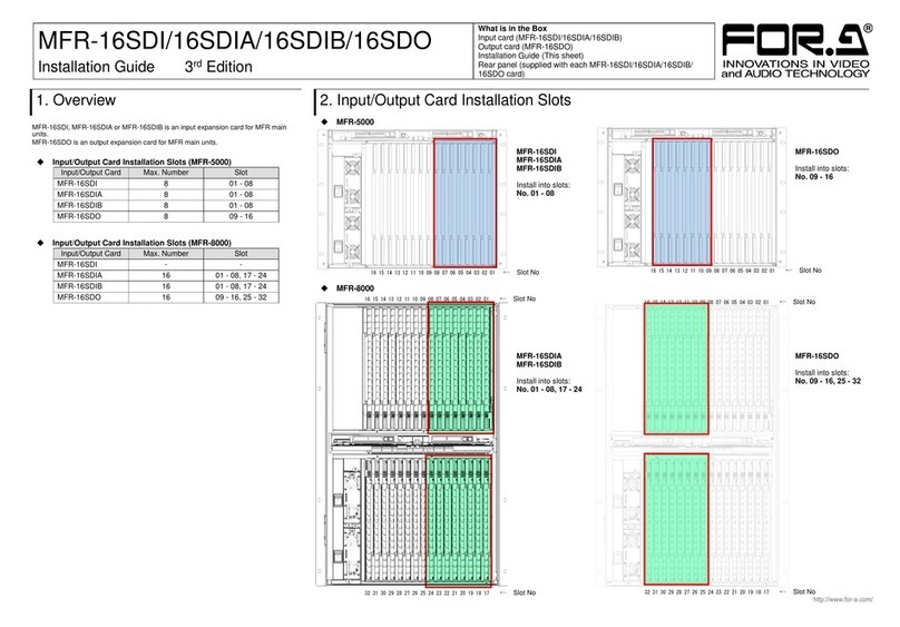
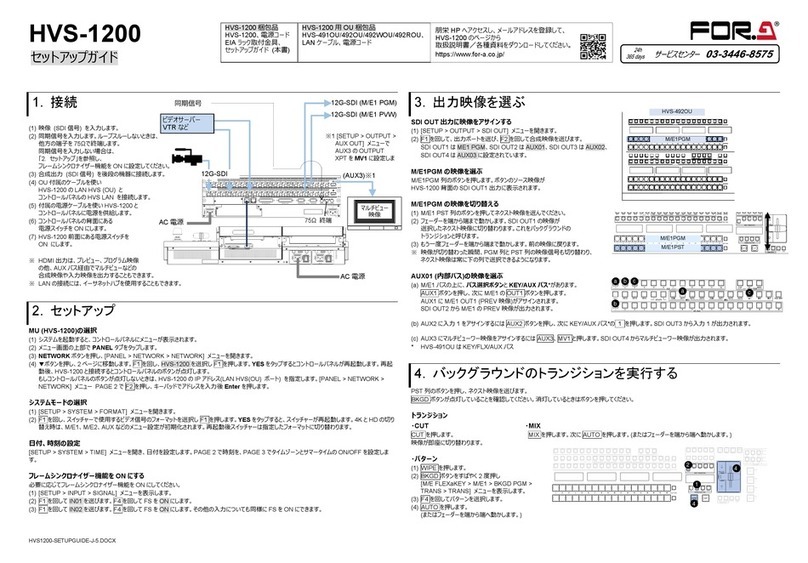
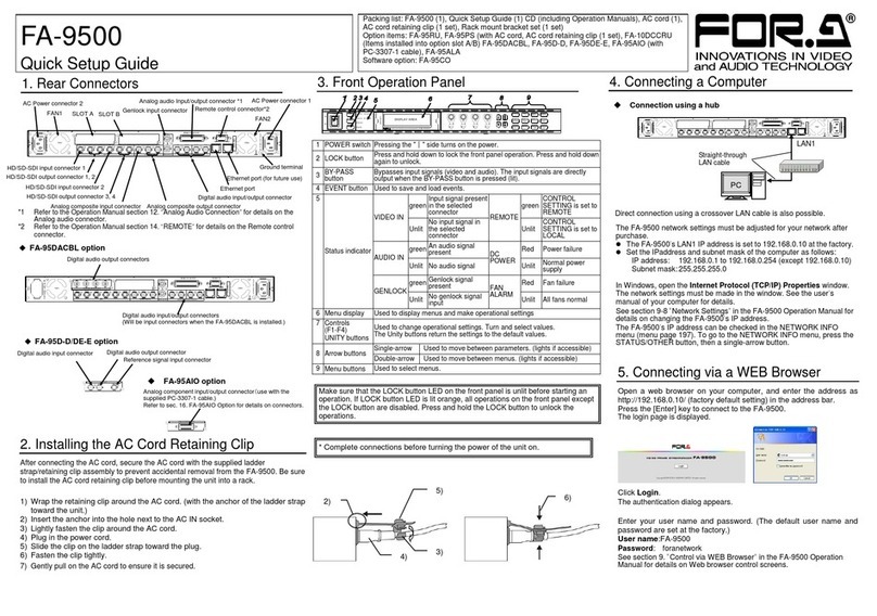
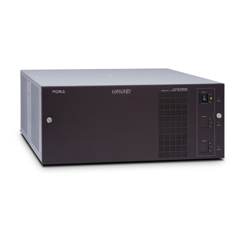
FOR-A FA-1010 User manual

FA-1010
Frame Synchronizer
FA-10PS
1st Edition - Rev.2
Version 1.10 or Higher
OPERATION
MANUAL

2
Edition Revision History
Edit.
Rev.
Date
Description
Section/Page
-
-
2013/07/31
Provisional
1
-
2013/08/30
First edition
1
1
2013/09/02
Corrected one dimension.
7-1
1
2
2013/09/18
Added Audio functions.
4-3, etc.

3
Precautions
Important Safety Warnings
[Power]
Operate unit only at the specified supply voltage.
Disconnect the power cord via the power plug only. Do not pull on the cable portion.
Do not place or drop heavy or sharp-edged objects on the power cord. A damaged
cord can cause fire or electrical shock hazards. Regularly check the power cord for
excessive wear or damage to avoid possible fire / electrical hazards.
[Grounding]
Ensure the unit is properly grounded at all times to prevent electrical shock.
Do not ground the unit to gas lines, units, or fixtures of an explosive or dangerous
nature.
Ensure the power cord is firmly plugged into the AC outlet.
[Operation]
Do not operate the unit under hazardous or potentially explosive atmospheric
conditions. Doing so could result in fire, explosion, or other hazardous results.
Do not allow liquids,metal pieces, or otherforeign materials to enter the unit. Doing
so could result in fire, other hazards, or a unit malfunction.
If a foreign material does enter the unit, turn the power off and immediately
disconnect the power cord. Remove the material and contact an authorized service
representative if damage has occurred.
[Transportation]
Handle with care to avoid impact shock during transit, which may cause
malfunction. When you need to transport the unit, use the original or suitable
alternative packing material.
Stop
Caution
Hazard
MHazard
Caution
Hazard
Caution
Caution

4
[Circuitry Access]
Do not remove covers, panels, casing, or access the circuitry with power applied to
the unit. Turn the power off and disconnect the power cord prior to removal. Internal
servicing / adjustment of unit should only be performed by qualified personnel.
Do not touch any parts / circuitry with a high heat factor.
Capacitors can retain enough electric charge to cause mild to serious shock, even
after the power has been disconnected. Capacitors associated with the power
supply are especially hazardous.
Unit should not be operated or stored with cover, panels, and / or casing removed.
Operating the unit with circuitry exposed could result in electric shock / fire hazards
or a unit malfunction.
[Potential Hazards]
If abnormal odors or noises are noticed coming from the unit, immediately turn the
power off and disconnect the power cord to avoid potentially hazardous conditions.
If problems similar to the above occur, contact an authorized service representative
before attempting to operate the unit again.
[Rack Mount Brackets, Ground Terminal, and Rubber Feet]
To rack-mount or ground the unit, or to install rubber feet, do not use screws or
materials other than those supplied. Doing so may cause damage to the internal
circuits or components of the unit. If you remove the rubber feet that are attached to
the unit, do not reinsert the screws that secure the rubber feet.
[Consumables]
Consumable items that are used in the unit must be periodically replaced. For
further details on which parts are consumables and when they should be replaced,
refer to the specifications at the end of the Operation Manual. Since the service life
of the consumables varies greatly depending on the environment in which they are
used, such items should be replaced at an early date. For details on replacing
consumable items, contact your dealer.
Caution
Hazard
Stop
Caution
Caution

5
Upon Receipt
Unpacking
FA-1010 units and their accessories are fully inspected and adjusted prior to shipment.
Operation can be performed immediately upon completing all required connections and
operational settings.
Check your received items against the packing lists below. Check to ensure no damage has
occurred during shipment. If damage has occurred, or items are missing, inform your supplier
immediately.
ITEM
QTY
REMARKS
FA-1010
1
AC Cord
1 set
(Including AC cord retaining clip)
Rack Mount Brackets
1 set
EIA standard type (Including 4 screws)
CD-ROM
1
Windows GUI installation disc
(Including operation manual (PDF))
Quick Setup Guide
1
Option
ITEM
QTY
REMARKS
FA-10PS
1 set
Redundant power supply unit (Including AC
cord and AC cord retaining clip).
FA-10ANA-AUD
1
Analog audio I/O card
FA-10AES-BL
1-4
Digital audio (balanced) I/O card
FA-10AES-UBL
1-4
Digital audio (unbalanced) I/O card
FA-10AES-UBLC
1-4
Digital audio (unbalanced) Output expansion
cable
* The FA-10AES-UBL functions as an input
card when used with the FA-10AES-UBLC.
FA-10GPI
1
GPI control card
Trademarks
Microsoft, and Windows are either registered trademarks or trademarks of Microsoft
Corporation in the United States and/or other countries.
Intel, Intel Core, Pentium are trademarks of Intel Corporation in the U.S. and/or other
countries.
* All other trademarks are trademarks or registered trademarks of their respective owners.
Rack Mounting
FA-1010 can be mounted to EIA standard rack units. When rack mounting a unit, remove the
rubber feet and use the accessory rack mount brackets (rack ears).

6
Table of Contents
1. Prior to Starting ...........................................................................................................................9
1-1. Welcome ..............................................................................................................................9
1-2. Features...............................................................................................................................9
1-3. About This Manual...............................................................................................................9
2. Panel Descriptions ....................................................................................................................10
2-1. Front Panel.........................................................................................................................10
2-2. Rear Panel .........................................................................................................................11
2-3. Internal Settings.................................................................................................................12
2-3-1. Dipswitch Settings.......................................................................................................12
3. System Setup............................................................................................................................13
3-1. System Configuration.........................................................................................................13
3-1-1. Option Slots.................................................................................................................13
3-2. Power-On...........................................................................................................................14
3-2-1. Note on Powering Off..................................................................................................14
3-3. Windows GUI Setup...........................................................................................................14
3-3-1. System Requirements.................................................................................................14
3-3-2. Network Settings.........................................................................................................14
3-3-3. Installing Software.......................................................................................................15
4. Windows GUI ............................................................................................................................18
4-1. Main Unit............................................................................................................................19
4-2. Video Block (Video Signal Control)....................................................................................20
4-2-1. FS Input.......................................................................................................................21
4-2-2. Video Loss Mode........................................................................................................22
4-2-3. Video System..............................................................................................................23
4-2-3-1. Sync Mode...........................................................................................................23
4-2-3-2. System Phase......................................................................................................24
4-2-3-3. Video Position......................................................................................................24
4-2-3-4. Freeze Mode........................................................................................................24
4-2-4. Frame Delay................................................................................................................25
4-2-5. Video Process Amplifier..............................................................................................26
4-2-5-1. Link Mode Setting Example.................................................................................27
4-2-6. Color Corrector ...........................................................................................................28
4-2-7. Video Clip....................................................................................................................30
4-2-8. Video Test Signal........................................................................................................32
4-2-9. SDI Multiplexer............................................................................................................33
4-2-9-1. Embedded Audio Multiplexer...............................................................................34
4-2-9-2. Timecode.............................................................................................................35
4-2-10. Clean Switch.............................................................................................................36
4-2-10-1. Take Mode Operation........................................................................................37
4-2-10-2. Salvo Mode........................................................................................................37
4-2-11. FS Output..................................................................................................................39
4-2-12. By-pass.....................................................................................................................40
4-2-13. Video Status..............................................................................................................41
4-3. Audio Block (Audio Signal Control)....................................................................................42
4-3-1. Audio Input Status.......................................................................................................43

7
4-3-1-1. Audio Input Status - Detail.................................................................................. 43
4-3-2. Embedded Audio Demultiplex.................................................................................... 44
4-3-3. Sampling Rate Converter (SRC)................................................................................ 45
4-3-4. Polarity Mode ............................................................................................................. 46
4-3-5. Down Mix.................................................................................................................... 47
4-3-5-1. Downmix Assign.................................................................................................. 48
4-3-6. Audio Mapping ........................................................................................................... 50
4-3-7. Audio Test Signal....................................................................................................... 52
4-3-8. Master Mute ............................................................................................................... 53
4-3-9. Mono Sum Mode........................................................................................................ 54
4-3-10. Audio Gain................................................................................................................ 55
4-3-11. Audio Delay.............................................................................................................. 56
4-3-12. Embedded Audio Multiplex...................................................................................... 57
4-3-13. Audio System........................................................................................................... 58
4-3-14. Audio Output Status................................................................................................. 59
4-4. Status ................................................................................................................................ 60
4-5. Utility.................................................................................................................................. 61
4-5-1. Event Control.............................................................................................................. 61
4-5-1-1. Event Name Edit................................................................................................. 62
4-5-2. Backup Parameter ..................................................................................................... 62
4-5-3. Event Data Backup .................................................................................................... 63
4-6. Network ............................................................................................................................. 65
4-6-1. Network Settings........................................................................................................ 65
4-6-2. SNMP Settings........................................................................................................... 65
5. Menu List.................................................................................................................................. 67
5-1. Video Block........................................................................................................................ 67
5-2. Audio Block........................................................................................................................ 68
6. Troubleshooting........................................................................................................................ 69
7. Specifications and Dimensions ................................................................................................ 70
7-1. Specifications .................................................................................................................... 70
7-2. External Dimensions ......................................................................................................... 72


9
1. Prior to Starting
1-1. Welcome
Congratulations! By purchasing a FA-1010 Frame Synchronizer you have entered the world of
FOR-A and its many innovative products. Thank you for your patronage and we hope you will
turn to FOR-A products again and again to satisfy your video and audio needs.
FOR-A provides a wide range of products, from basic support units to complex system
controllers, which have been increasingly joined by products for computer video-based systems.
Whatever your needs, talk to your FOR-A representative.We will do our best to be of continuing
service to you.
1-2. Features
Developed as an all-round unit, the FA-1010 frame synchronizer comes equipped with 10 signal
processing channels in a compact 1RU body. Color correction and logo generation video signal
processing functions and remapping/embedding of 160-channel embedded audio in 10 SDI
signal inputs have been added as standard to the various frame synchronizer functions of the
FA-1010. Moreover, by installing additional optional functions into the 4 built-in slots, the unit is
able to function optimally under all types of video production scenes, including those for
transmission, outside broadcasting, news reporting, production, editing and distribution.
Standard Features
Color correction
Powerful frame synchronizer
Audio embedding
3G-SDI support (Level A)
Routing
Pass-through of ancillary data such as closed captioning or time code data
Other standard features
Video delay
Monitoring and control via dedicated GUI
SNMP monitoring
Optional Features
Redundant power supply
Analog audio input/output (Planned option)
Digital audio input/output (balanced/unbalanced) (Planned option)
GPI control (Planned option)
1-3. About This Manual
This manual is intended to help the user easily operate this product and make full use of its
functions during operation. Before connecting or operating your unit, read this operation manual
thoroughly to ensure you understand the product. Afterwards, it is important to keep this manual
in a safe place and available for reference.

10
2. Panel Descriptions
2-1. Front Panel
No
Name
Description
1
Power switch
Used to turn the unit ON / OFF.
2
Unit status
indicator
DC
POWER
1/2
Lit green
Power supply is normal.
Lit red
A power failure has occurred.
FAN
ALARM
Lit green
All fans are operating normally.
Lit red
One or more fans have failed.
GENLOCK
Lit green
Genlock signal input is present.
Unlit
No genlock signal input is present.
LTC IN
Lit green
LTC input is present.
Unlit
No LTC input is present.
3
SDI IN status
indicator
BY-PASS
Lit green
Input signal is being bypassed.
Unlit
No signal is being bypassed.
VIDEO
Lit green
Video signal input is present.
Unlit
No video signal input is present.
AUDIO
Lit green
Embedded audio signal is present.
Unlit
No embedded audio signal is present.
4
OPTION SLOT
status indicator
INSTALL
Lit green
One or more option cards are found and
recognized in option slots A to D.
Unlit
No option card is installed or recognized.
VIDEO IN
Lit green
Video signal input(s) is/are present in option
slot(s).
Unlit
No video signal input in option slots.
AUDIO IN
Lit green
Audio signal input(s) is/are present in option
slot(s).
Unlit
No audio signal input in option slots.
5
INITIALIZATION
Used to reinitialize the unit. Read the WARNING below before
proceding. To reinitialize the unit, turn the unit on while holding down
the INITIALIZATION button.
WARNING
All setting data will initialize. Back up before executing a reinitialization.
FA-1010
FRAME SYNCHRONIZER
INITIALIZATION
OPTIONSLOT
A B C D
INSTALL
VIDEOIN
AUDIOIN
BY-PASS
VIDEO
AUDIO
1 2 3 4 5 6 7 8 9 10
DC POWER1 GENLOCK
DC POWER2
FANALARM LTCIN
SDI IN
(1)
(2)
(3)
(4)
(5)

11
2-2. Rear Panel
No
Name
Description
1
LAN
1000/100BASE-TX Ethernet LAN port. Used to connect to an external
remote control unit or transfer data to an external device. RJ-45
2
SDI IN 1-10
3G/HD/SD-SDI video signal input connectors. Each IN and OUT 1 to 10 are
allocated as a pair. The left connectors of each pair are input connectors.
3
SDI OUT 1-10
3G/HD/SD-SDI video signal output connectors. Each IN and OUT 1 to 10
are allocated as a pair. The right connectors of each pair are output
connectors.
4
GENLOCK IN
Genlock signal input connector. Used for reference signal input (black burst
or tri-level sync). The bottom connector is for a loop through. Terminate at
75 ohm when not in use.
5
Ground
Terminal
Used to ground the unit to protect operators from static electricity and
electrical shock.
6
AC IN 2
AC power source connector. (100-240V AC 50/60Hz)(optional)
7
LTC IN/OUT
Time code input/output connector
8
Option Slot A
Option card installation slot.
9
Option Slot B
Option card installation slot.
10
Option Slot C
Option card installation slot.
11
Option Slot D
Option card installation slot.
12
AC IN 1
AC power source connector. (100-240V AC 50/60Hz)
IMPORTANT
Internal cooling fans prevent overheating. Do not block the front, rear or side vents
with other equipment or objects.
AC1 00-240V 50 /60Hz IN 1
GENLOCK IN
SER.NO.
OUT10IN 10OUT 9
D
IN 9OUT 8IN 8OUT 7IN 7OUT 6IN 6
C
3G / HD / SD - SDI
OUT 5
B
IN 5OUT 4IN 4OUT 3IN3
A
OUT 2IN 2OUT 1IN 1
LTCIN / OUT
LAN
AC 100-240 V 50/60 Hz IN 2
(9)
(1)
(2) Left connector.
(3) Right connector.
(4)
(5)
(7)
(6)
(8)
(10)
(11)
(12)

12
2-3. Internal Settings
IMPORTANT
Note that internal switch settings should remain unchanged from factory default
settings under most operational circumstances. If you have accidentally changed the
setting, refer to the MAIN card settings below to return to the factory default settings.
Further note that adjustment and maintenance should only be performed by qualified
technical personnel familiar with FOR-A equipment.
WARNING
Do not access internal cards or connect peripheral units with the unit power ON.
Always power OFF all connected units / disconnect power cords prior to accessing the
interior. To protect boards from electrostatic damage, do not touch board components.
2-3-1. Dipswitch Settings
The following dipswitch settings can be made on the MAIN CARD inside the FA-1010.
Dipswitch DS1 Settings
Pin No.
Default
Settings
DS1
1-8
OFF
Do not change
DS2
1
ON
Do not change
2-8
OFF

13
3. System Setup
3-1. System Configuration
FA-1010 base system device connections are shown below with the 10 SDI inputs and outputs
standard.
3-1-1. Option Slots
Up to 4 option cards can be installed into SLOTS A to D to enhance your system.
Currently available options are as follows:
FA-10ANA-AUD
Analog audio input/output option
FA-10AES-BL
Digital audio (balanced) input/output option
FA-10AES-UBL
Digital audio (unbalanced) input/output option
FA-10AES-UBLC
Digital audio (unbalanced) input/output expansion option
FA-10GPI
GPI control option
AC1 00-240V 50/ 60Hz I N 1
GENLOCKIN
SER.NO.
OUT10IN 10OUT9
D
IN 9OUT 8IN8OUT 7IN 7OUT6IN6
C
3G / HD / SD - SDI
OUT5
B
IN 5OUT4IN4OUT3IN3
A
OUT2IN2OUT 1IN1
LTCIN / OUT
LAN
AC1 00-240V 5 0/60Hz IN 2
・・・・
Option slots
SLOT A
SLOT B
SLOT C
SLOT D
LTC IN/OUT
Time code input
and output
GENLOCK IN
External reference
signal input
AC IN 1
AC IN 2(option)
LAN
SDI IN
SDI OUT
3G/HD/SD-SDI input and output connectors.
Alternate Input and output allocation. Bypass outputs
signal input (left) to the right of each input/output
connector pair.
Hub
Windows GUI
Cameras, switchers, etc.
Monitors, recorders, etc.
GENLOCK IN
Loop-through
(Terminate at
75Ωwhen not
in use.)
・・・・ モニターモニター
モニター モニター

14
3-2. Power-On
When the FA-1010 is powered on, all LEDs on the front panel including Alarm indicators light.
Once startup is complete, current status is indicated.
3-2-1. Note on Powering Off
Do not turn the power of the unit for at least 10 seconds whenever a setting is changed.
Otherwise the setting data may not be properly saved.
3-3. Windows GUI Setup
3-3-1. System Requirements
To install Product (software), your computer must meet the following requirements.
OS
Windows® 7, 8 operating system
Professional (32/64 bit)
CPU
Intel® Core™2 Duo processor
2 GHz or faster
Memory
2 GB or more
Display
Resolution of 1280 x 1024pixels or higher recommended
Must be capable of full color (24-bit) display
Network port
Ethernet, at least one port
100BASE-TX/1000BASE-T
Network cable
100BASE-TX: Category 5 or better
1000BASE-T: Category 6, or enhanced category 5
Software
Microsoft® .NET Framework 4.0
Windows® Installer 3.1
* Mac OS is not supported.
3-3-2. Network Settings
Change the PC network settings for the connection with the FA-1010.
From the Startup menu, go to Local Area Connection > General > Internet Protocol
(TCP/IP) > General > Properties, then set the IP address and Subnet mask asshown below.
PC IP address
192.168.0.xxx (xxx is any number from 1 to 254 except for the
number set for the FA-1010 unit and the gateway number.)
Subnet mask
255.255.255.0
* The default FA-1010 IP address is 192.168.0.10.

15
3-3-3. Installing Software
(1)Open the CD-ROM, and the FA-1010GUI folder. Double-click the Setup icon to start the
setup wizard.
(2)If “Microsoft .NET Framework 4”is not installed on your PC, the screen as sown below
appears. Click Accept.
* If “Microsoft .NET Framework 4”is already installed on your PC, the screen will not
appear.
(3)If “Microsoft Visual Basic Power Packs 10.0”is not installed on your PC, the screen as
shown below appears. Click Accept.
* If “Microsoft Visual Basic Power Packs 10.0”is already installed on your PC, the
screen will not appear.

16
(4)Once the FA-1010GUI setup wizard starts, the screen as shown below appears. Click
Next to continue the setup.
(5)Select the installation directory, then click Next.
(6)A confirmation screen will appear. Click Next to start the installation.
(7)The user Account Control screen will appear. Click Yes to continue the installation.

17
(8)When installation is completed, the screen as shown below appears. Click Close to quit
the setup wizard.

18
4. Windows GUI
This section describes Windows GUI, the dedicated FA-1010 control software that runs in a PC.
Refer to section 3-3-2. “Network Settings”when establishing a PC connection.
When FA-1010 GUI starts up, a page as shown below opens.
Enter the FA-1010 IP address to register the unit. Up to 10 units can be registered.
Select a unit to connect under Select, then click Connect. A menu page opens.
* Simultaneous connections with multiple units are not possible.
Item
Description
Select
Allows you to select an FA-1010 to connect or enter Unit and FS
names.
IP Address
Allows you to enter the IP address of each FA-1010 unit.
Description
Allows you to enter a note.
Button
Description
Connect
Allows you to establish a connection with the selected FA-1010.
Disconnect
Allows you to release the connection.
Abort
Allows you to cancel the connection.

19
4-1. Main Unit
The Main Unit tab at the top of the screen allows you to open the Main Unit page as shown
below.
Windows GUI allows you to register up to 10 FA-1010 units with unit names and FS names.
Item
Description
Select
Allows you to select an FA-1010 to connect or enter Unit and FS
names. The FA-1010 unit selection cannot be changed while one unit
is connected.
IP Address
Allows you to enter the IP address. The IP address cannot be changed
while the unit is connected.
Description
Allows you to enter a note. Unchangeable during connection.
Unit / FS Name
Allows you to enter the unit name and FS names for the selected
FA-1010.
Button
Description
Connect
Allows you to establish a connection with the selected FA-1010.
Disconnect
Allows you to release the connection. Release the current connection
to connect to another FA-1010 unit.
Apply
Allows you to apply settings.
* Unit/FS Name is visible and changeable only if an FA-1010 is connected.

20
4-2. Video Block (Video Signal Control)
Click the Video tab at the top of the page. The video block diagram will be displayed.
Each block in the diagram lets you go to the corresponding windows or dialog boxes that allow
you to change various settings.
Other manuals for FA-1010
1
This manual suits for next models
1
Table of contents
Other FOR-A Computer Hardware manuals

FOR-A
FOR-A FA-9520 User manual

FOR-A
FOR-A MFR-16SDOA User manual

FOR-A
FOR-A HVS-1200 User manual

FOR-A
FOR-A MFR-16AESI User manual

FOR-A
FOR-A MFR-41CPU User manual

FOR-A
FOR-A FA-10PS Installation manual

FOR-A
FOR-A HVS-2000EX User manual

FOR-A
FOR-A HVS-2000MV User manual

FOR-A
FOR-A MFR-16MADIPO User manual

FOR-A
FOR-A HVS-490 User manual