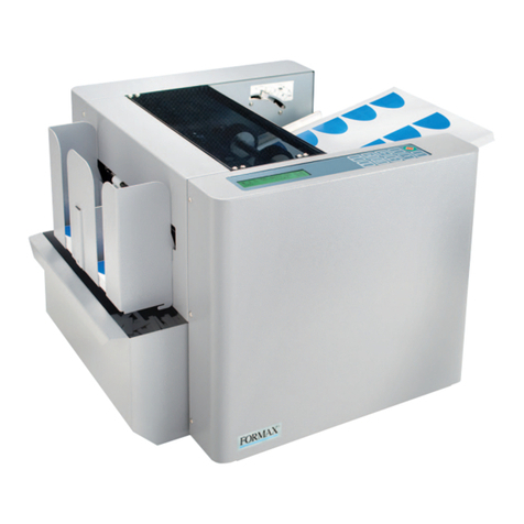
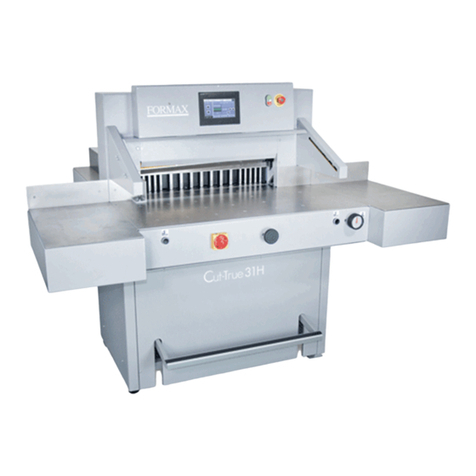
Formax Cut-True 31H User manual

Cut-True 31H
Guillotine Cutter
OPERATOR MANUAL
Second Edition
8/2019


Delivery status
(assembly of the tables according to Figure below)
The cutter is supplied by the manufacturer with the disassembled side tables

Fig 6. Tightening of side tables
1. Left side table + screw M10x20 (4 pcs) + washer 8 (4 pcs.)
2. Right side table + screw M10x20 (4 pcs) + washer 8 (4 pcs)
Danger!
Protect the power cable from sharp tools, high temperature and oil.
Setting the cutter
Adjusting the cutter setting.

The cutter does not need to be attached to the ground. The correct and safe setting
of the machine is achieved by turning the adjusting foot 1, and locking its position
with the nut 2, as shown on the previous page.
about 0.5 m around the device. (see below)
3.5 Work area
.

4. TECHNICAL CHARACTERISTICS OF THE CUTTER
The cutter is intended for trimming paper, and is primarily used in printing
houses, bookbinding shops, and offices.
Main parameters
Technical data
Maximum stack width
730mm
28.7”
Maximum stack height
100mm
3.9”
Cutting depth
730mm
28.7”
Front table length
640mm
25”
Narrow cut
30mm
1.18”
60mm
2.36”
Noise level
74.6 dB
Backgauge speed
58mm/s
1.9 fps
Side table load
20kg
44 lbs
Machine weight
610kg
1,345 lbs
Technical data –electronics (see following page)

Table 5.
Parameter
Maximum power (kW)
3
Voltage / frequency
(V/Hz)
400/50 - 60
Fuse (A)
3x20
3x30
4.2.3 Technical data- hydraulic system
4.2.3.1 Technical data- hydraulic appratus
Table 6.
Parameter
Motor power (kW)
2.2
47.2 mm²
Voltage / frequency
(V/Hz)
3x400/50
2x220/60
Control of executive elements (VDC)
24
Tank capacity (l)
12
4.2.3.2 Technical data- oil for hydraulics
Table 7.
Parameter
Oil type
HV 46
Quality
ISO 11158 - HV
Viscosity
ISO VG 46
Norm DIN
51524, 46 mm2
(cST).
Kinematic viscosity in temperature (40°C)
The hydraulic system does not require de-aeration, it takes place automatically after
several cuts.

4.2.4 External dimensions
The dimensions of the cutter are shown in Figure 9 and Table 6.
Figure 9. Dimensions of the cutter
DIMENSION
VALUE
(mm/inch)
A
1445 / 57”
B
924 / 36”
C
1754 / 69”
D
1857 / 73”
E
114 / 4.48”
F
658 / 26”
G
376 / 14.8”
H
1,105 / 43.5”
X
640 / 25”
Y program
710 / 27.9”
Y1 manual
730 / 28.7”
Table 6.

5. OPERATION
5.1 Operating safety
5.1.1 Safety instructions
• Before each start-up or start-up on the cutter, the next change should be made to
ensure that the safety components are complete and work properly.
• The cutter can only be operated if all safety components and safeguards such as
detachable covers, emergency stop switches are installed and fully functional.
• In case of a malfunction, stop the cutter immediately and block it.
• All defects must be eliminated immediately.
5.1.2 Warning about special hazards
You should refrain from performing any actions that violate safety in the machine.
In particular, it is prohibited to:
• Putting your hands into the field of knife and clamp.
• Put your hands into the field between the clamping and infeed bars.
• Exercise extreme caution when handling the knife! Use the transport brackets
when installing / removing / carrying the knife.
• Use only undamaged and sharp knives!
• The knife can only be changed by trained personnel.
• When cutting on the work table, there must be no objects (such as keys,
screwdrivers)
5.2 Control system
Danger!
The cutter cannot be operated with defective photocells forming the safety
curtain!

Figure 10. Control and signaling elements of the Cut-True 31H
1. Main switch
2. Palm button, (emergency stop)
3. Locking button of the control system
4. Button that activates the control system.
5. Buttons enabling the cutting cycle (two-handed cutting start-up system)
6. Hydraulic pressure adjustment crank
- turn right - pressure increase
- turn left - pressure decrease
7. Two-color signal lamp.
- red, signals the power supply to the control system
- green, signals the activation of the control system
8. program unit
9. Light curtain (non-contact protection device)
9a. Transmitter
9b. Receiver
10. Foot pedal (mechanical determination of the cutting line)

Figure 11. Receiver indicators
The receiver is equipped with six LEDs informing about the operating status:
Table 7.
Position
LED colour
Indication
Text
1
Red/green
Status OSSD
OSSD
2
Red
Error indication
ERR
3
Blue
Quality of signal
1 2 3 4
Blue LEDs informing about the quality of the settings, in conjunction with a flashing red
color LED ERR, also indicate errors.
Table 8. Blue LEDs informing about the quality of the settings
LEDs informing
about quality
settings
Diode LED OSSD
Meaning
It does not light up
no LED
red
The setting is insufficient or
the protective field is
interrupted at least

partially. The receiver can
not
synchronize with the
transmitter.
It lights up 1
led
red
The setting is insufficient or
the protective field is
interrupted at least
partially.
It lights up 2
led
red
The setting is insufficient or
the protective field is
interrupted at least
partially.
It lights up 2
led
green
The setting is not yet
sufficient to ensure
stable availability.
It lights up 3
Led
green
The setting is good, stable
availability.
It lights up 4
led
green
The setting is very good.
Figure 12. Transmitter indicators
The transmitter is equipped with two LEDs informing about the operating status:

Table 9.
Position
LED diode color
Indication
Text
1
yellow
Work status
indicator
PWR
2
red
Error indication
ERR
5.3 Electrical apparatus
The cutter is supplied with a five-core copper wire with 2.5 mm2 wire cross-
section. The user's duty is to install the cutter to the electrical network with 20 A
safeguards. For connecting, use a copper wire with a cross-sectional area of 2.5
mm2 or more. Voltage fluctuations should be in the range of 90-110% of the
rated voltage, and frequency fluctuations in the range of 50 Hz ± 2%.
The cutter can be connected to a five-core, L1, L2, L3, N, PE electric network.
Danger!
Dangerous electrical voltage!
Before opening the housing, switch off the main switch!
1. Hinged housing of electrical apparatus (Fig. 13)
2. Nuts fixing the housing (Fig. 13)
Figure 13. Location of electrical apparatus

6. POWER SUPPLY
Figure 14. Location of the nameplate
Data on the plate:
- 400V power supply
- 50-60 Hz frequency
- 3 kW power
- 20 A protection
WARNING
The data on the plate must correspond to the current parameters in the mains!
Parameters of frequency converters (inverters) are set by the cutter
manufacturer and can not be changed!
Cutter should be grounded!

7. USING OF THE CUTTER
The user is obliged to create working conditions at the machine
workplace that preclude the operator from slipping, slipping or falling due to
poor ground conditions, cable routing or lack of convenient access!
7.1 Work area for operational staff
The working area is the front side of the (operational) cutter!
7.2 Danger zones in the cutter
• knife and clamp zone
• back side of the cutter frame (access to clamp zone and knife)
•back side of the cutter (access to the backgauge)
• bottom side of the rear table access to the backguage zone (spindle and slider)
7.3 Starting up the cutter
7.3.1 Starting the cutter
Figure 15. Arrangement of the elements used when starting the cutter.

1. Set the main switch 1 to "ON" 1
2. Press the green 2 "I" button
- LED 3 lights up green
- the green OSSD 1 LED lights up (Fig.11) in the receiver 4 (Fig.15)
If after turning on the power supply with the main switch 1 (Fig. 15) and
pressing the green button 2, the LED 3 is green, the connection is correct
(correct direction of rotation), if the LED is red, the connection is not correct
and should be replaced in the plug two of three phase conductors.
Figure 16. Light curtain
1. Transmitter
2. Receiver
A - field of the light curtain

7.3.2 Indications (diagnostics) of the safety curtain after switching on the
power supply.
When the cutter is switched on, the transmitter 1 and receiver 2 are initialized
(fig. 16). All transmitter and receiver LEDs will light for a moment. After initialization the
receiver indicates the quality of the setting using four blue LEDs 3 (Fig.11). Table 8.
The setting indicator extinguishes after a suitable time when the safety light curtain is
set (the LED of the device switching the output signal: green item 1 figure 11) and only
the PWR LED of transmitter 1 (fig.12) and LED 1 (fig. 11) device for switching the
receiver's output signal. In the event of an error on the device, the red LED will light. On
the side receiver red error LED - in combination with blue LEDs - indicates the cause of
the error.
Danger!
In case of malfunction of photocells, immediately contact the service!
7.3.3 Emergency stop of the cutter
1. Press the button 5 (Fig. 15)
The switch is used for emergency stopping of the machine.
After pressing it, the message "Disable safety button" will appear on the programmer.
The pressure bar and knife will stop.
7.3.4 Starting the cutter after emergency stop
1. Unlock button 5 (turn it around) (Fig.15)
2. Press the green 2 "I" button
When the stop has been made during the cutting cycle, pressing the cutting buttons
again will result in returning to the upper position of the clamping beam and the knife
7.4 Determining the position of the approaching beam
Danger!
Do not put your hands into the cutting area when backgauge moves!

Determining the position of the approaching beam is carried out using the
programmer 1 and the hand wheel 2, figure 17.
The method of determining the position of the beam as well as the operation of
the programmer are described in the "Instructions for operating the
programmer".
7.4.1 Changing the position of the beam with the hand wheel
1. Press knob 2
2. Turn the knob to bring the beam closer or closer by reading the position value on
the programmer screen.
Figure 17. Arrangement of the positioning elements for the position of the backgauge.

7.5 Clamping the paper
The clamping of the paper stack takes place automatically after pressing the
buttons that start the cutting cycle 1 (fig. 18).
Danger!
Do not put your hands into the cutting area when pressing!
7.5.1 Manual clamping of cut material (mechanical cutting line
determination)
Lower the pressure beam into the stack by pressing the pedal 3 (Fig.18). The front
edge of the clamping bar is the same as the cutting line. Therefore, it can be used as
an indicator of the cutting line. The clamp can be stopped in any position.
Figure 18. Operating elements when used during clamping.

7.5.2 Changing the clamping force
The change of clamping force can be done by manual crank rotation 3 and
reading the value of pressure on manometer 4 (fig. 18)
turning right - clamp pressure increase
turning left- clamp pressure decrease
Approximate values of the clamping force depending on the pressure value
read on the pressure gauge (manometer) 4
25 bar ~ 300 daN
40 bar ~ 650 daN
55 bar ~ 1000 daN
70 bar ~ 1350 daN
90 bar ~ 1700 daN
110 bar ~ 2000 daN
7.5.3 Rules for selecting the clamping force.
The value of the pressing force is selected experimentally, in relation to the
type, width and height of the cut material.
The following rules must be observed:
• the higher the pile, the greater the downforce
• the greater the cutting width, the greater the downforce
• the harder the material, the greater the downforce
7.6 Cutting line indicator (optical)
The cutter is equipped with an optical cutting line indicator. A thin light line
indicates the cutting line on the material to be cut.
7.7 Cutting (clamping and cutting)
Danger!
Do not put hands into cutting zone!
Other manuals for Cut-True 31H
2
Table of contents
Other Formax Cutter manuals

Formax
Formax Cut-True 29H User manual

Formax
Formax FD 120 User manual

Formax
Formax FD 125 User manual

Formax
Formax FD 574 User manual

Formax
Formax Cut-True 29A Owner's manual

Formax
Formax Cut-True 29A User manual

Formax
Formax Cut-True 31H User manual

Formax
Formax FD 574 User manual
Formax
Formax FD 125 User manual