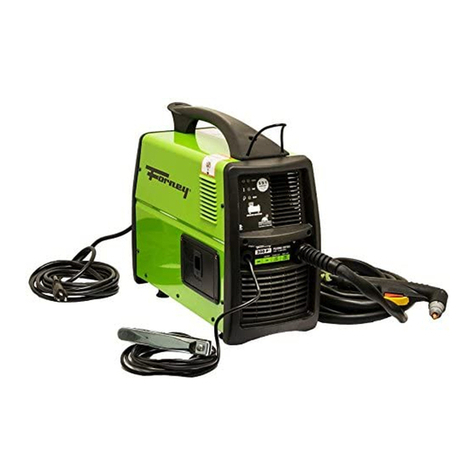
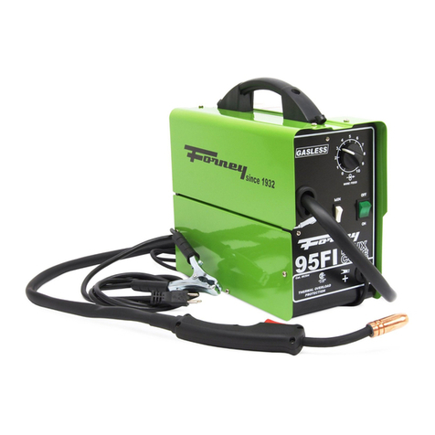
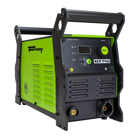
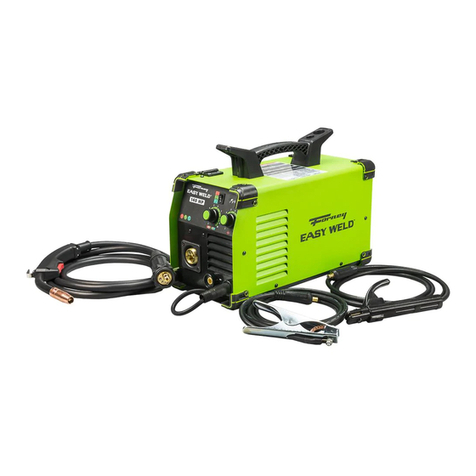
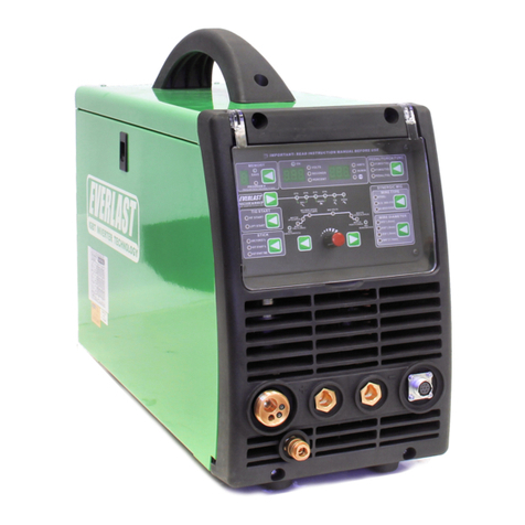
Forney 95FI User manual

Cat. 00304 8/1/09
95FI
TwecofJ Style Torch
Infin ite W ire S peed C ontr ol
Multiple Power settings
· Th erm al o erlo ad P rotec iion
W elds all types
of:
• Mild (Carbon) Steel
• Stainless Steel
• Cast Iron
Complefe & Ready to W eld
Com es with: Operating Manual.
Set-Up Cf!art Spool of Flux Cored
Wire. Extro Contact Tips. Chipping
Hammer & Brush Combo &
W elding Face Shield

and maintenance of welding equipment.
7) HIJKJLMMHNOP
A) Implied warranties.including those of merchantability a
duration to this express warranty. After this period, all risk
the purchaser.
B) Any incidental,Indirect, or consequential loss, damage.
failure or malfunction of the Forney product.
C) Any failure that results from accident. purchaser's abu
accordance with instructions pro ided inthe owner's m
D) Pre-deli ery ser ice, i.e. assembly and adjustment.
8) QPIn the e ent of a warranty claim under this warranty, the
sole option:
A) Repair: or
B) Replacement; or
C) Wher e authorized In writing by Forney Industries, the co
·Forney Industries ser ice staHon; or
D) Payment of or credit for the purchase price less reason
the return of the goods at the customer's risk and expen
9) RKHINP
A) Contact Forney's customer ser ice at 1-800-521-6038 w
. B) Pro ide dated proof of purchase (typically a purchase
C) Pro ide the serial number. Registering your welder at fo
this process.
D) Deli er or ship welder to a Forney authorized ser ice ce
be borne by the purchaser.


A procedure step preceded by a WARNING
is an indication that the next step contains a
procedure that might be injurious to a person
if proper safety precautions are not heeded.
A procedure preceded by a CAUTION is an
indication that the next step contains a pro§
cedure that might damage the equipment
being used.
A NOTE may be used before or after a pro
cedur step to highlight or explain something
in that step.
READ ALL SAFETY INSTRUCTIONS
CAREFULLY before attempting to install,
operate, or ser ice this welder. Failure to
comply with these instructions could result in
personal injury and/or property damage.
RETAIN THESE INSTRUCTIONS FOR
FUTURE REFERENCE_
Note:
• The following safety alert symbols identify
important safety messages in this manual.
•
T
S
in
m
in

d. any metal parts on the electrode
holder, or wire feed gun.
• Do not weld in a damp area or come in
contact with a moist or wet s_urface.
• Do not attempt to weld if a·ny part of
clothing or body is wet.
• Do not allow the welding equipment to
come in contact with water or moisture.
• Do not drag welding cables, wire feed
gun, or welder power cord through or
allow them to come into contact with
water or moisture.
• Do not touch welder, attempt to tum
welder on or off if any part of the body or
clothing ·is moist or if you are in physical
contact with water or moisture.
• Do not attempt to plug the welder into the
power source if any part of body or cloth§
ing is moist, or if you are in physical con§
tact with water or moisture.
• Do not connect welder work piece clamp
to or weld on electrical condu'it.
• Do not alter power cord or power cord
plug in any way.
• Do not attempt to plug the welder
AR
BU
fro
the
ma
we
we
sa
filte
da
•
•
•

helmet and replace any cracked or bro§
ken filter lenses IMMEDIATELY.
• Do not allow the uninsulated portion
of the wire feed gun to touch the ground
clamp or grounded work to pre ent an
arc flash from being created on contact.
• Pro ide bystanders with shields or hel§
mets fitted with a #10 shade filter lens.
Wear protecti e clothing. The intense
light of the welding arc can burn the skin
in much the same way as the sun, e en
through light-weight clothing. Wear dark
clothing of hea y material. The shirt worn
should be long slee ed and the collar
kept buttoned to
.protect chest and neck.
Protect against REFLECTED ARC RAYS.
Arc rays can be reflected off shiny sur§
faces such as a glossy painted surface,
aluminum, st{:linless steel, and glass. It is
possible for your eyes to be injured by
reflected arc rays e en when wearing a
protecti e helmet or shield. If welding with
a reflecti e surface behind you, arc rays
can bounce off the surface, then off the fil§
ter lens on the inside of your helmet or
shield, then into your eyes. If a reflecti e
background exists in your welding area,
either remo e it or co er it with something
non-flammable and non-reflecti e.
Reflecti e arc rays can also cause skin
bum in addition to eye injury.
XYZY[
li ] W A R N I N G
R[\ Y\Y[
Y]X^\_`^Y\RR]`Ya
YbTo reduce the risk of death, injury, or
property damage from fire or explosion, read,
understand, and follow the following safety
instructions. In addition, make certain that
anyone else that uses this welding equfp§
ment, or is a bystander in the welding area,
understands and follows these safety instruc§
tions .as well. REMEMBER! Arc welding by
nature produces sparks, hot spatter, molten
metal drops, hot slag, and hot metal parts that
can start fires, burn skin, and damage eyes.
Do not wear glo es or other clothing that
contains oil, grease, or other flammable
substances.
Do not wear flammable hair preparations.
Do not weld in an area until it is checked
and cleared of combustible and/or flam§
mable materials. BE AWARE that sparks
and slag can fly 35 feet and can pass
through small cracks and openings. If
work and combustibles cannot be sepa§
rated by a minimum of 35 feet, protect
against ignition with suitable, snug-fitting,
fire resistant, co ers or shields.
Do not weld on walls until checking for
and remo ing combustibles touching the
other side of the walls.
• Do not weld, cut, or perform other such
work on used barrels, drums, tanks, or
other containers that had contained a
flammable or toxic substance. The tech§
niques for remo ing flammable sub§
stance and apors, to make a used con§
tainer safe for welding or cutting, are
quite complex and require special educa§
tion and training.
Do not strike an arc on a compressed
gas or air cylinder or other pressure es§
sel. Doing so will create a brittle area tha1
can result in a iolent rupture immediate§
ly or at a later time as a result of rough
handling.
Do not weld or cut in an area where the
air may contain flammable dust (such as
grain dust), gas, or liquid apors (such as
gasoline) .
• Do not handle hot metal, such as the
work piece or electrode stubs, with bare
hands.
Wear leather glo es, hea y long slee e
shirt,cuffless trousers, high-topped
shoes,helmet, and cap. As necessary,
use additional protecti e clothing such as
leather jacket or slee es, fire resistant
leggings, or apron. Hot sparks or metal
can lodge in rolled up slee es, trouser
cuffs, or pockets. Slee es and collars
should be kept buttoned and pockets
eliminated from the shirt front.
• Ha e fire extinguisher equipment handy
for immediate use! A portable chemical
fire extinguisher, type ABC, is recom§
mended.
Wear ear plugs when welding o erhead to
pre ent spatter or slag from falling into ear.
• Make sure welding area has a good,
solid, safe floor, preferably concrete or
masonry, not tiled, carpeted, or made of
6
not adequate to exchange aff fumes and
gasses generated during the welding
process with fresh air, do not weld unless
you (the welder) and all bystanders are
wearing air-supplied respirators.
• Do not heat metals coated with, or that
contain, materials that produce toxic
fumes (such as gal anized steel), unless
the coating is remo ed. Make certain the
area is well entilated, and the operator
and all bystanders are wearing air-sup§
plied respirators.
• Do not weld, cut, or heat lead, zinc, cad§
mium, mercury, beryllium, or similar met..
als without seeking professional ad ice
and inspection of the entilation of the
welding area. These metals produce
EXTREMELY TOXIC fumes which can
cause discomfort, illness, and death.
• Do not weld or cut in areas that are near
chlorinated sol ents. Vapors from chlori§
nated hydrocarbo-ns, such as trichloroeth§
ylene and perchtoroethylene, can be
decomposed by the heat of an electric
arc or its ultra iolet radiation. These
actions can cause PHOSGENE, a HIGH-

BRAZING -obtainable from your state
OSHA office or U.S. Dept. of Labor
OSHA, Office of Public Affairs, Room
N3647, 200 Constitution A e.,
W ashington, DC 20210 - www.osha.go
• CSA Standard W 117 .2 - Code for SAFE §
TY IN W ELDING AND CUTTING. -
obtainablefromCanadianStandards
Association, 178 Rexdale Bl d.,
Etobicoke, Ontario M 9W 1R3
-
ww w.csa.ca
• American Welding Society Standard
A6.0. WELDING AND CUTTING CON §
TAINERS WHICH HAVE HELD COM §
BUSTIBLES. - obtainable from the
American W elding Society, 550 NW Le
Jeune Road, M·iami, FL 33126 Telephone
(800) 443"9353, Fax (305) 443-7559-
www.amweld.org or www.aws.org

]``
The duty cycle rating of a welder defines
how long the operator can weld and how
long the welder must be rested and cooled.
Duty cyc\e is expressed as a percentage of
10 minutes and represents the maximum
welding time allowed. The balance of the 10-
minute cycle is required for cooling.
Your new welder has a duty cycle rating of
20o/o at the rated output. This means that you
can weld for two (2) minutes out of 10 with
the remaining eight (8) minutes required for
cooling. (See Table 2).
]f2. Duty Cycle Ratings
Duty
Cycle
Rating
Maximum
Welding
Time
Required
Resting
Time
40%
60o/o
80%
4 minutes
6 minutes
8 minutes
6 minutes
4 minutes
2 minutes
100o/o 10 minutes 0 minutes

the speed at which the welder feeds wire to
the gun. 1 is the slowest wire feed speed, 10
is the highest. You will need to adjust or
·"tune-in" your wire speed for different welding
conditions (thickness of metals, metal type,
wire size, etc.). When the wire speed is prop
erly "tuned-in" the welding wire will melt into
the material you rewelding as quickly as it is
fed through the welding gun.
Voltage Selector - This two position switch
adjusts the oltage or "heat" of your welder.
Select MIN setting for lower oltage and
MAX setting for higher oltage. Different
materials and material thickness will require
different oltage settings. You will need to
adjust your oltage accordingly for different
welding conditions. By properly adjusting
your oltage settings and wire feed speed,
you will enable clean, precision welds. (Refer
to the Suggested Settings Chart on p.29 of
this manual.)
i
g
Y
w
a
w
W
w
o
u
w
o
s
w
a
t
s
t
a
t
w
w
p

operated on inadequate or excessi e power.
EXTENSION CORDS
For optimum welder performance, an extension
cord should not be used unless absolutely nec§
essary. If necessary, care must be taken in
selecting an extension cord appropriate for use
with your specific welder.
Select a properly grounded extension cord
that will mate directly with the ac power
source receptacle and the welder power cord
without the use of adapters. Make certain
that the extension cord is properly wired and
in good electrical condition.Extension cords
must fit the following wire size guidelines:
• 0..25 ft. requires #12 gauge
• Do not use an extension cord o er
25ft. in length.
ASSEMBLING THE WELDER
The following procedures describe the process
required to assemble, install, maintain, and pre§
pare to weld with your new wire feed welder.
I
1
2
3

Handle
Co er
Handle
I
Extra
Material
Dark
Glass
. . . f 8 l - - - - R e ta in in g
Clip
in
1
2
3
4
Retaining
Clip
Retaining
Tabs
Figure 2. Face Shield Assembly

WARNING
ARC RAYS CAN INJURE EYESI
To reduce the risk of arc flash, make certain
that the welding wire, when it finally comes
out of the end of the gun, does not touch the
ground clamp or any grounded piece of
metal. IMPORTANT! The welding wire is car§
rying welding current whene er the welder is
turned on.
11. Pull the trigger on the welding gun to feed
the wire through the gun assembly.
12. When at least an inch of wire sticks out
past the end of the gun, release the trigger.
13. Install the supplied 0.040 inch (1.0mm)
size contact tip.
Note: Due to inherent ariances in flux§
cored welding wire, it may be necessary
to use a welding tip one size larger than
your flux-core wire if jams occur.
14. Slide the contact tip o er the wire (pro§
truding from the end of the gun). Screw
a
u
W
s
th
a
th

The VOLTAGE .SELECTOR allows you to
select minimum and aximum eat settings.
Refer to the Suggested Settings Chart on
p.29 of this manual for suggestions on which
heat setting to use for your welding job.
PREPARATIONS FOR WELDING
An important factor in making a satisfactory
weld is preparation. This includes studying
the process and equipment and then practice
welding before attempting to weld finished
product. An organized, safe, con enient,
comfortable, well-lighted work area should be
a ailable to the operator. The work area
shoufd specifically be free of arf flammables
with both a fire extinguisher and bucket of
sand a ailable.
To properly prepare for welding, it is
necessary to:
• Prepare an organized, wen lit work area
(see Figure 5).
t
S
W
W
in
H
e
e
b
is
w
p
s
P
F
jo
p
c
I
o
e

p;@1
•
37.5"
SINGLE BEVEL JOINT
DOUBLE BEVEL JOINT
31'32" TO Hs-
CLOSED
y
JOINT
oo· _-
_
u
,1[
§
--.-. OPEN JOINT
.
-
.
- - - - -
·}(,_
DOUBLE VEE JOINT
FILLET WE
SINGLE FILLET
lAP JOtNT
SINGLE.
STRAP JOINT DOUBLE STRAP JOINT
Figure 7. Types o

process of trial and error. The best way to
teach yourself how to weld is with short peri§
ods of practice at regular inter als. All prac§
tice welds should be done on scrap metal
that can be discarded. Do not attempt to
make any repairs on aluable equipment
until you ha e satisfied yourself that your
practice welds are of good appearance and
free of slag or gas inclusions. What you fail
to learn through practice will be learned
through mistakes and re-welds later on.
HOLDING THE GUN
The best way to hold the welding gun is the
way that feels most comfortable to you.
While practicing to use your new welder,
experiment holding the gun in different posi§
tions until you find the one that seems to
work best for you.
Position the Gun to the Work Piece
There are two angles of the gun nozzle in
relation to the work piece that must be con§
sidered when welding.

are adequately protected. Wear flameproof
welding glo es, a hea y long slee ed shirt,
cuffless trousers, high topped shoes and a
welding helmet.
WARNING
ELECTRIC SHOCK CAN KILL! To pre ent
ELECTRIC SHOCK, do not perform any
welding while standing, kneeling, or lying
directly on the grQunded work.
WELDING TECHNIQUES
MOVING THE GUN
Gun tra el refers to the mo ement of the gun
·along the weld joint and is broken into two el&
ments: Direction and Spepd. A solid weld bead
requires that the welding gun be mo ed
steadify and at the right speed afong the weld
joint. Mo ing the gun too fast, too stow, or
erratically will pre ent proper fusion or create a
lumpy, une en bead.

Figure 12. Weave Bead
WELDING POSITIONS
There are three basic welding positions: flat,
horizontal, and ertical.
1. The FLAT POSITION (Figure 13) is the
easiest of the welding positions and is proba§
bly the one you ha e been using thus far. It
is best if you can weld in the flat position if at
all possible as good results are easier to
achie e.
Figure 13. Flat Position

Figure 16. Butt Joints
Fillet Weld Joints. Most fillet weld joints, on
metals of moderate to hea y thickness,
·will
require multiple pass welds to produce a
strong joint. The illustrations in Figure 17
show the sequence of laying ·multiple pass
beads into a T fillet joint and a1ap fillet joint.
1

each side of the lap joint seam.
Select the wire diameter, heat setting, and
tune-in the wire speed as if you were
welding the same thickness material with
a continuous bead.
SPOT WELDING INSTRUCTIONS
1. Select the wire diameter and ·heat setting
recommended abo e for the method of
. spot welding you intend to use.
2. Tune in the wire speed as if you were
going to make a continuous weld.
3. Hold the nozzle piece completely perpen§
dicular to and about 1/4 inch off the work
pr
•
ece.
4. Pull the trigger on the gun and release it
when it appears that the desired penetra§
tion has been achie ed.
5. Make practice spot welds on scrap metal,
arying the length of time you hold the
trigger, until a desired spot weld is made.
6. Make spot welds on the actual work piece
at desired locations.
L
r
u
b
C
I
C
F
T
M
T
tr
w
s
A
s
N
w
c
w
Other manuals for 95FI
1
Table of contents
Other Forney Welding System manuals

Forney
Forney 125 FC User manual

Forney
Forney 220 ST User manual

Forney
Forney 190 MP User manual

Forney
Forney 140 MP User manual

Forney
Forney 95FI-A User manual

Forney
Forney 430 User manual

Forney
Forney 317 User manual

Forney
Forney 95FI User manual

Forney
Forney 220 TIG AC/DC User manual

Forney
Forney 270 User manual

Forney
Forney 410 User manual

Forney
Forney 190 User manual

Forney
Forney 220 MP User manual

Forney
Forney 242 User manual

Forney
Forney 140 MIG WELDER User manual

Forney
Forney Easy Weld 20P User manual

Forney
Forney 270 MIG User manual

Forney
Forney 220 AC/DC User manual

Forney
Forney 180 ST+ User manual

Forney
Forney Easy Weld series User manual