manuals.online logo
Brands
  1. Home
  2. •
  3. Brands
  4. •
  5. Fortin
  6. •
  7. Automobile Accessories
  8. •
  9. Fortin EVO ONE THAR-GM7 User manual

Fortin EVO ONE THAR-GM7 User manual

1-Page_entete
WARNING
ATTENTION
A11 OFF
NON
*
HOOD
PIN
HOOD STATUS : THE HOOD PIN SWITCH (INCLUDED)
MUST BE INSTALLED IF THE VEHICLE CAN BE
REMOTE STARTED WITH THE HOOD OPEN, SET FUNCTION A11 TO OFF.
CONTACT
DE CAPOT
SECURITY STICKER
AUTOCOLLANT DE
SÉCURITÉ
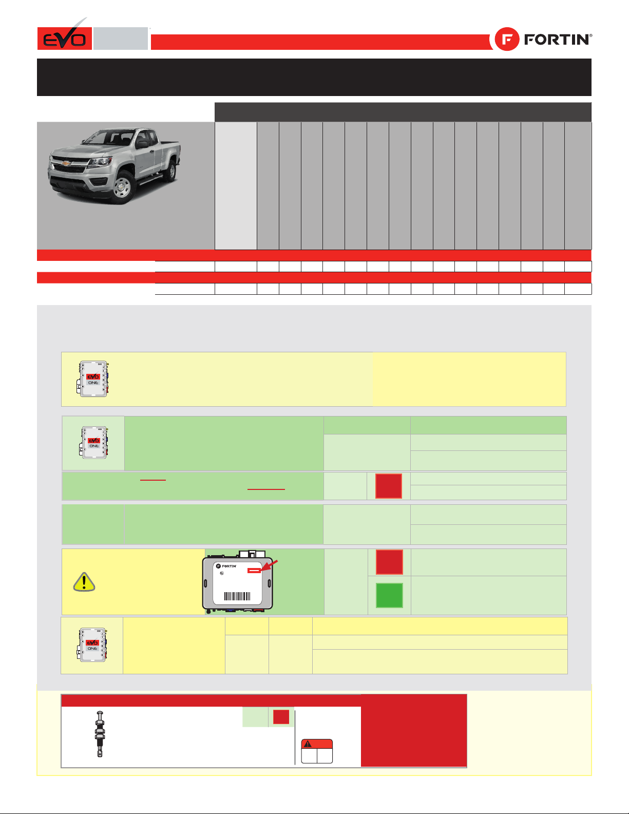
MANDATORY INSTALL | INSTALLATION OBLIGATOIRE Notice: the installation of safety
elements are mandatory. The hood pin
and the sticker are essential security
elements and must be installed.
Notice: l'installation des éléments de
sécurité est obligatoire. Le contact de
capot et l'autocollant de sécurité sont
des éléments de sécurité essentiels et
doivent absolument être installés.
THIS MODULE MUST BE INSTALLED BY A
QUALIFIED TECHNICIAN. A WRONG
CONNECTION CAN CAUSE PERMANENT
DAMAGE TO THE VEHICLE.
CE MODULE DOIT ÊTRE INSTALLÉ PAR
UN TECHNICIEN QUALIFIÉ, TOUTE
ERREUR DANS LES BRANCHEMENTS
PEUT OCCASIONNER DES DOMMAGES
PERMANENTS AU VÉHICULE.
STATUT DE CAPOT : LE CONTACT DE CAPOT (INCLUS), DOIT ÊTRE
INSTALLÉ SI LE VÉHICULE PEUT DÉMARRER À DISTANCE, LORSQUE LE
CAPOT EST OUVERT, PROGRAMMEZ LA FONCTION A11 À NON.
Included
Inclus
ONE REV.: 20220217
ADDENDUM - SUGGESTED WIRING CONFIGURATION
ADDENDA - SCHÉMA DE BRANCHEMENT SUGGÉRÉ
Contents
Supported functions & Function programming | Fonctions supportées et programmation des fonctions—1
Photo & Location | Photos & Emplacements—2
WIRE TO WIRE Connection Diagram - Automatic Transmission | Diagramme de Branchements FIL À FIL - Transmission Automatique—3
THAR-GM7 - THarness Diagram- Automatic Transmission | Diagramme harnais en T- Transmission Automatique—4
Key Bypass Programming Procedure | Procédure de Programmation Contournement de Clé—5
Remote starter programming procedure | Remote starter functionality | Procédure de programmation du démarreur à dis-
tance | Fonctionalité du démarreur à distance—7
Disclaimer | Avertissement—8
Program remote
starter option for R.S. OEM
REMOTE STAND ALONE:
Programmez l’option
démarreur à distance pour
TÉLÉCOMMANDE D’ORIGI-
NE STAND ALONE:
FUNCTION
FONCTION MODE DESCRIPTION
38 2Enable : Press 3x Lock to remote start with the OEM remote.
Activé : Appuyez x3 sur Verrouille de la télécommance d’origine
pour démarrer à distance le véhicule.
Program bypass option:
Programmez l’option du contournement:
UNIT OPTION
OPTION UNITE DESCRIPTION
C1
OEM Remote status (Lock/Unlock)
monitoring
Suivi des status (Verrouillage/Déverrouil-
lage) de la télécommande d’origine
ATTENTION!
Date: xx-xx
REMOTE STARTER & ALARM
& BYPASS MODULE
Made in Canada
Démarreur à Distance, Alarme & Bypass
Waranty void if opened
Service No : X
www.fortinbypass.com
Starter : X
EVO-ONE : X
EVO-ONE
DATE: XX-XX
E5
OFF
NON By default DEACTIVATED
Par defaut DÉSACTIVÉ
ON
OUI
MANUFACTURED MODULES
BETWEEN: 04/2018 TO 04/2019
MODULES MANUFACTURÉS
ENTRE: 04/2018 AU 04/2019
IF THE VEHICLE IS NOT EQUIPPED WITH FUNCTIONAL HOOD PIN:
SI LE VÉHICULE N’EST PAS ÉQUIPÉ
D’UN CONTACT DE CAPOT FONCTIONNEL: A11 OFF
NON
Hood trigger (Output Status).
Contact de capot (état de sortie).
Program bypass option
(If equiped with OEM alarm):
Programmez l’option du contournement
(Si équipé d’une alarme d’origine):
D2
Unlock before / Lock after (Disarm OEM
alarm)
Déverrouille avant / Verrouille après
(Désarme l’alarme d’origine)
BYPASS FIRMWARE VERSION
VERSION LOGICIELLE CONTOURNEMENT
To add the rmware version and the options, use the
FLASH LINK UPDATER or FLASH LINK MOBILE tool,
sold separately.
Pour ajouter la version logicielle et les options,
utilisez l’outil FLASH LINK UPDATER
ou FLASH LINK MOBILE, vendu séparément.
70.[45]
MINIMUM
Vehicle functions supported in this diagram (functional if equipped) | Fonctions du véhicule supportées dans ce diagramme (fonction-
nelles si équipé)
VEHICLE
VEHICULES
YEARS
ANNÉES
Immobilizer bypass
Contournement
d’immobilisateur
Lock
Unlock
Arm
Disarm
Trunk (open)
RAP Disable
Tachometer
Door Status
Trunk Status
Hood Status*
Hand-Brake Status
Foot-Brake Status
PK3, Passlock
OEM remote Monitoring**
R.S. OEM remote
Stand Alone compatible
CHEVROLET
Colorado
2021-2022
•
•
•
•
•
•
•
•
•
•
•
•
•
•
•
•
GMC
Canyon
2021-2022
•
•
•
•
•
•
•
•
•
•
•
•
•
•
•
•
Guide #100051
Supported functions & Function programming | Fonctions supportées et programmation des
fonctions
REGULAR AND THAR-GM7 THARNESS INSTALLATION
INSTALLATION RÉGULIÈRE ET HARNAIS THAR-GM7
Page 1 / 9
This guide may change without notice. See www.fortin.ca for latest version.
Ce guide peut faire l’objet de changement sans préavis. Voir www.fortin.ca pour la récente version.
DESCRIPTION |DESCRIPTION
1 2 34
8
9 10 11 12 13 14
15 18 19 20
21 24 25 26
56 7
16 17
23
22
8
9 10 11 12 13 14 15
24 25 26 27
567
22 23
18 19 20 21
16 17
1234
8 9 10 11 12 13 14
15 16 17 18 19 20
21 22 23 24 25
13457
26
BCM - On the left of the steering column
BCM – À gauche de la colonne de direction
(~) IMMO
DATA (MUX)
PASSLOCK
(+) IGNITION
(~) SWC
(+) 12V
(+)ACCESSORY
(-) PARKING
LIGHTS
(-) UNLOCK
(-) LOCK
AT BCM
AU BCM
Photo & Location | Photos & Emplacements
Page 2 / 9
Yellow In A1
Purple Out A2
Purple/White Out A3
Green Out A4
White Out A5
Orange Out A6
Orange/Black Out A7
Dk.Blue Out A8
Red/Blue In A9
Lt.Blue/Black In/Out A10
Black In A11
Pink Out A12
Yellow/Black Out A13
Brown/White In A14
Pink/Black In A15
Purple/Yellow In/Out A16
Green/White In/Out A17
Green/Red In/Out A18
White/Black Out A19
Lt.Blue In/Out A20
C5 Brown
C4 Gray/Black
C3 Gray
C2 Orange/Brown
C1 Orange/Green
D6 White/Red
D5 White/Blue
D4 White/Green
D3 Yellow/Red
D2 Yellow/Blue
D1 Yellow/Green
White Out E1
Orange Out E2
Red In E3
Black In E4
Pink In/Out E5
Yellow Out E6
This guide may change without notice. See www.fortin.ca for latest version.
Ce guide peut faire l’objet de changement sans préavis. Voir www.fortin.ca pour la récente version.
WIRING CONNECTION | GUIDE DE BRANCHEMENTS
HOOD PIN
MANDATORY
CONTACT CAPOT
OBLIGATOIRE
(-) Hood pin
CUT LOOP FOR AUTOMATIC
TRANSMISSION MODE.
COUPEZ LA BOUCLE POUR LE
MODE TRANSMISSION
AUTOMATIQUE.
(-)Ground
(+)12V
(-)Parking Lights
(-)Unlock
(-)Lock
(+)Ignion
A2
A3
A4
A5
A6
A7
A8
A9
A10
A11
A12
A13
A14
A15
A16
A17
A18
A19
A20
E1
E2
E3
E4
E5
E6
C5
C4
C3
C2
C1
D6
D5
D4
D3
D2
D1
A1
D1
D5
C1
C2
C3
C4
E6
E5
E2
E1
A19
A17
A14
A13
A11
A8
A7
A6
A5
A4
w/o OnStar
Lt. Green/
Purple
Vert Pâle/
Mauve
Lt. Green/
Purple
Vert Pâle/
Mauve
Gray/Black
Gris/Noir
Gray/Black
Gris/Noir
Purple/Black
Mauve/Noir
Purple/Black
Mauve/Noir
White/Purple
Blanc/Mauve
White/Purple
Blanc/Mauve
Red/Yellow
Rouge/Jaune
Red/Yellow or
Red/Purple
Rouge/Jaune ou
Rouge/Mauve
Lt.Green
VertPâle Green/Gray
Vert/Gris
Lt.Green
VertPâle Green/Gray
Vert/Gris
COLORADO
CANYON
w OnStar
COLORADO
CANYON
BCM - On the left
of the steering
column
BCM – À gauche
de la colonne de
direction
Purple/Yellow
Mauve/Jaune Brown/White
Brun/Blanc
Brown/Yellow
Brun/Jaune
Not Connected
Non Connecté Not Connected
Non Connecté
Not Connected
Non Connecté
Back view
27-Pin Blue
Connector
At BCM
Vue de dos
Connecteur Bleu
de 27-Pins
Au BCM
Back view
25-Pin Green
Connector
At BCM
Vue de dos
Connecteur Vert
de 25-Pins
Au BCM
Back view
26-Pin White
Connector
At BCM
Vue de dos
Connecteur Blanc
de 26-Pins
Au BCM
1 2 34
8
9 10 11 1213 14
15 18 19 20
21 24 25 26
56 7
16 17
23
22
8
9 10 11 12 13 14 15
24 25 26 27
567
22 23
18 19 20 21
16 17
1234
8 9 10 11 12 13 14
15 16 17 18 19 20
21 22 23 24 25
13457
26
10
4
5
6
7
8
9
19
20
21
17
16
14
15
13
12 18
11
25
24
23
22
1
2
3
10
4
5
6
7
8
9
19
20
21
17
16
14
15
13
12 18
11
27
25
24
23
22
26
1
2
3
10
4
5
6
7
8
9
19
20
21
17
16
14
15
13
12
1811
25
24
23
22
26
1
2
3
(~) IMMO
DATA (~) IMMO
POWER (MUX)
PASSLOCK (+)
12V (~)
SWC (-) PARKING
LIGHTS
A10/A20 A18 C5
(+)
IGNITION
6
19
15
5
(+)
ACCESSORY* (-)
LOCK* (-)
UNLOCK*
*IF THE VEHICLE
IS NOT
EQUIPPED WITH
THE ON-STAR
®
SYSTEM.
*SI LE VÉHICULE
N’EST PAS
ÉQUIPÉ DU
SYSTÈME
ON-STAR
®
CUT
D4
A9/D6
(~)CAN SW
(~)Immo Data
(~)Immo Data
(+)Igni�on
(+)12V
(MUX)Passlock
(~)Immo Power
(~)Immo Power
(~)Immo Power
D3/A1
D3/A1
E3/D2
E3/D2
A12
A20
Ground
2 Amp
Fuse
Fusible
A2 A3A16
(+)Accessory
WIRE TO WIRE Connection Diagram - Automatic Transmission | Diagramme de Branchements FIL À FIL - Transmission Automatique
Page 3 / 9
Yellow In A1
Purple Out A2
Purple/White Out A3
Green Out A4
White Out A5
Orange Out A6
Orange/Black Out A7
Dk.Blue Out A8
Red/Blue In A9
Lt.Blue/Black In/Out A10
Black In A11
Pink Out A12
Yellow/Black Out A13
Brown/White In A14
Pink/Black In A15
Purple/Yellow In/Out A16
Green/White In/Out A17
Green/Red In/Out A18
White/Black Out A19
Lt.Blue In/Out A20
C5 Brown
C4 Gray/Black
C3 Gray
C2 Orange/Brown
C1 Orange/Green
D6 White/Red
D5 White/Blue
D4 White/Green
D3 Yellow/Red
D2 Yellow/Blue
D1 Yellow/Green
White Out E1
Orange Out E2
Red In E3
Black In E4
Pink In/Out E5
Yellow Out E6
This guide may change without notice. See www.fortin.ca for latest version.
Ce guide peut faire l’objet de changement sans préavis. Voir www.fortin.ca pour la récente version.
CUT LOOP FOR AUTOMATIC
TRANSMISSION MODE.
COUPEZ LA BOUCLE POUR LE
MODE TRANSMISSION
AUTOMATIQUE.
THAR-GM7 | AUTOMATIC TRANSMISSION CONNECTION | BRANCHEMENT TRANSMISSION AUTOMATIQUE
A2
A3
A4
A5
A6
A7
A8
A9
A10
A11
A12
A13
A14
A15
A16
A17
A18
A19
A20
E1
E2
E3
E4
E5
E6
C5
C4
C3
C2
C1
D6
D5
D4
D3
D2
D1
A1
D1
D5
C1
C2
C3
C4
E6
E5
E2
E1
Protect the main connector
with electrical tape to prevent
shortcircuit to ground.
Protégez le connecteur
principal avec du ruban
électrique pour éviter les
cours-circuit avec la masse.
A19
A17
A13
A11
A8
A7
A6
A4
27 PINS MALE
T-HARNESS PLUG
CONNECTEUR MÂLE
DU T-HARNAIS
FEMALE T-HARNESS PLUG
CONNECTEUR FEMELLE
DU T-HARNAIS
26 PINS MALE
T-HARNESS PLUG
CONNECTEUR MÂLE
DU T-HARNAIS
FEMALE T-HARNESS PLUG
CONNECTEUR FEMELLE
DU T-HARNAIS
MALE VEHICLE WHITE PLUG
CONNECTEUR BLANC MÂLE
DU VÉHICULE
25 PINS MALE
T-HARNESS PLUG
CONNECTEUR MÂLE
DU T-HARNAIS FEMALE T-HARNESS PLUG
CONNECTEUR FEMELLE
DU T-HARNAIS
MALE VEHICLE GREEN PLUG
CONNECTEUR VERT MÂLE
DU VÉHICULE
26 PINS WHITE CONN.
T-HARNESS - HARNAIS EN T
THAR-GM7
27 PINS BLUE CONN. 25 PINS GREEN/PINK CONN.
MALE VEHICLE BLUE PLUG
CONNECTEUR BLEU MÂLE
DU VÉHICULE
ISOLATE
NOT CONNECTED
---------------------
ISOLER
NON BRANCHÉ
PURPLE | MAUVE
PURPLE/WHITE | MAUVE/BLANC
1
A
A
B
B
C
C
ISOLATE
NOT CONNECTED
---------------------
ISOLER
NON BRANCHÉ
A
B
w/o OnStar
COLORADO
CANYON
w OnStar
COLORADO
CANYON
BCM - On the left
of the steering
column
BCM – À gauche
de la colonne de
direction
1
NOT CONNECTED
NE PAS BRANCHER
5 PIN CONN.
NOT CONNECTED
NE PAS BRANCHER
EVO-ONE
EVO-ALL
6 PIN RED CONN.
THAR-GM7 - THarness Diagram - Automatic Transmission | Diagramme harnais en T - Transmission Automatique
Page 4 / 9
RELEASE
x5
A
E
F
GJ
I
H
B
C
D
Release
Relâchez
the programming
button when the LED is
YELLOW.
le bouton de
programmation quand la DEL
est JAUNE.
If the LED is not solid YELLOW
the 6-Pin connector
(Main-Harness) and go back to
step 1.
Si le DELn'est pas JAUNE
le connecteur 6 pins
(Connecteur principal) et au
début de l'étape 1.
disconnect
débranchez
allez
ON
Insert
Insérez
the required remaining connectors.
les connecteurs requis restants.
2
3
4
A
E
F
GJ
I
H
B
C
D
OFF
ON
ON
Turn
Tournez
ignition (ON).
the Ignition to the
ON/RUN position.
la clé en position
The RED LED will turns ON.
The YELLOW LED turns
OFF.
La DEL ROUGE s'allume.
La DEL JAUNE s'éteind.
Press release
Appuyez relâchez
and the programming
button five times (5x).
et 5 fois le bouton
de programmation.
The YELLOW LED will alternate
between 5x flashes and a pause.
until the YELLOW LED turns ON.
La DEL JAUNE alterne entre x5
clignotements et x1 pause.
que la DEL JAUNE s'allume.
Wait
Attendre
IGNITION OFF IGNITION ON
LOCK
ACCO N
PUSH
START
IGN
5
If the LED is not solid RED
the 6-Pin
connector (Main-Harness) and
go back to step 1.
Si le DELn'est pas ROUGE
solide le
connecteur 6 pins (Connecteur
principal) et au début de
l'étape 1.
disconnect
débranchez
allez
1
A
E
F
GJ
I
H
B
C
D
A
E
F
GJ
I
H
B
C
D
A
E
F
GJ
I
H
B
C
D
A
E
F
GJ
I
H
B
C
D
A
E
F
GJ
I
H
B
C
D
A
E
F
GJ
I
H
B
C
D
A
E
F
GJ
I
H
B
C
D
FLASH
ON
PRESS X5
...
ON
x1
HOLD
A
E
F
GJ
I
H
B
C
D
LED may differ depending on the module casing.
L’apparence des DELS peut différer selon le boîtier du module.






WITH T-HARNESS
AVEC HARNAIS EN T
Press and hold the
programming button:
Connect the 4-PIN Data-link
harness (Black connector).
Appuyez et maintenir le
bouton de programmation
enfoncé: Branchez le harnais
Data-Link à 4-Broches
(connecteur Noir)
Press and hold the
programming button: Insert
the 6-Pin Main connector.
Appuyez et maintenir le
bouton de programmation
enfoncé: Insérez le connec-
teur Principal à 6-broches.
x1
HOLD
A
E
F
GJ
I
H
B
C
D
The LEDs will alternate
between BLUE, RED, YELLOW
&BLUE/RED flashes.
Les DELs alterneront entre
un clignotement BLEU, ROUGE,
JAUNE & BLEU/ROUGE.
WITH
T-HARNESS
AVEC
HARNAIS EN T
If the LED is not solid YELLOW
disconnect the 4 Pin
connector (Data-Link)
and go back to step 1.
Si le DEL n'est pas JAUNE
solide débranchez le
connecteur 4 pins
(Data-Link) et allez
à l'étape 1.
A
E
F
GJ
I
H
B
C
D
CONTINUED NEXT PAGE | CONTINUEZ À LA PAGE SUIVANTE
5-Prog.1-1 LED JAUNE
This guide may change without notice. See www.fortin.ca for latest version.
Ce guide peut faire l’objet de changement sans préavis. Voir www.fortin.ca pour la récente version.
DCRYPTOR PROGRAMMING PROCEDURE |PROCÉDURE DE PROGRAMMATION AVEC DCRYPTOR
Parts required (not included) Pièces requises (non incluses)
1x FLASH LINK UPDATER,
1x FLASH LINK MANAGER
1x FLASH LINK MOBILE
1x FLASH LINK MOBILE APP
SOFTWARE | PROGRAMME
Smartphone Android or iOS with Internet connection
(Internet provider charges may apply)
Téléphone Intelligent Android ou iOS avec connection
Internet (des frais du fournisseur Internet peuvent s’appliquer)
OR
OU
Microsoft Windows Computer with Internet connection
Ordinateur Microsoft Windows avec connection Internet
1x1x
BEFORE PROGRAMMING SET THE UNIT OPTIONS AND SAVE. | AVANT LA PROGRAMMATION CONFIGURER LES OPTIONS DE L'UNITÉ ET SAUVEGARDER.
Key Bypass Programming Procedure | Procédure de Programmation Contournement de Clé
Page 5 / 9
A
E
F
GJ
I
H
B
C
D
A
E
F
GJ
I
H
B
C
D
A
E
F
GJ
I
H
B
C
D
A
E
F
GJ
I
H
B
C
D
A
E
F
G
J
I
H
B
C
D
A
E
F
G
J
I
H
B
C
D
A
E
F
GJ
I
H
B
C
D
A
E
F
GJ
I
H
B
C
D
A
E
F
GJ
I
H
B
C
D
A
E
F
GJ
I
H
B
C
D
Disconnect all connectors and after the 6-Pin (Main-Harness)
or the 4-Pin Data-link connector.
Débranchez tous les connecteurs et ensuite le connecteur
6-pins (Connecteur principal) ou le connecteur
4-pins (Data-Link).
REMOTE STARTER / ALARM VERIFICATION
PROCEDURE | PROCÉDURE DE VÉRIFICATION
DU DÉMARREUR À DISTANCE / ALARME
The module is now programmed.
Le module est programmé. Test the remote starter. Remote start the vehicle.
Testez le démarreur à distance. Démarrez le véhicule
à distance.
AFTER DCRYPTOR PROGRAMMING COMPLETED
Go back to the vehicle and reconnect the 6-Pin (Main-
Harness) or the 4-pins (Data-Link) connector
and after all the remaining connector.
APRÈS LA PROCÉDURE DE PROGRAMMATION
DCRYPTOR COMPLETÉE : retournez au véhicule et
rebranchez le connecteur 6-pins (Connecteur principal)
ou le 4-pins (Data-Link) et après tous les connecteurs.
FLASH LINK UPDATER*
FLASH LINK MOBILE*
FLASH LINK MANAGER*
SOFTWARE | PROGRAMME
A
E
F
GJ
I
H
B
C
D
A
E
F
GJ
I
H
B
C
D
Microsoft Windows
Computer with
Internet connection*
Ordinateur Microsoft
Windows avec
connection Internet*
*Pièces requises (non incluses)
Use the tool:
FLASH LINK UPDATER or
FLASH LINK MOBILE
to visit the DCryptor menu.
Utilisez l'outil:
FLASH LINK UPDATER ou
FLASH LINK MOBILE
pour visiter le menu DCryptor.
*Parts required (not included)
VEHICLE'S OBDII
CONNECTOR
CONNECTEUR OBDII
DU VÉHICULE
OR
OU Smartphone*
(Internet provider
charges
may apply)
Téléphone
Intelligent*
(des frais du
fournisseur
Internet peuvent
s’appliquer)
Turn the Ignition to the ON position.
The BLUE LED will turns ON.
Wait, the BLUE & RED LED will turns OFF.
Wait, the YELLOW LED will Flash.
Wait,the YELLOW LED will turns OFF.
Wait,the BLUE LED will Flash rapidly.
Tournez la clé à ON.
La DEL BLEU s'allume.
Attendre que la DEL BLEU et la DEL ROUGE
'éteignent.
Attendre que la DEL JAUNE clignote.
Attendre que la DEL JAUNE s'éteigne.
Attendre que la DEL BLEU clignote rapidement.
Wait 5 seconds.
Attendez 5 secondes.
the BLUE LED flash slowly. La DEL BLEU clignote
lentement.
Turn the key to the
OFF position.
Tournez la clé à la
position Arrêt (OFF).
LOCK
ACCON
PUSH
START
IGN
LOCK
ACCON
PUSH
START
OFF
IF THE VEHICLE IS
NOT EQUIPPED WITH
THE ON-STAR®
SYSTEM.
SI LE VÉHICULE NʼEST
PAS ÉQUIPÉ DU
SYSTÈME ON-STAR®
A
E
F
GJ
I
H
B
C
D
TION 2/2
CONTINUED NEXT PAGE | CONTINUEZ À LA PAGE SUIVANTE
FLASH RAPIDLY
ON
IGNITION ON
ON
IGNITION OFF
OFF
ON
OFF
FLASH OFF
WAIT If the LEDs do not react as
shown, the 6-Pin
connector (Main-Harness) and
go back to step 1.
Si les DELs ne réagissent pas
comme démontré,
le connecteur 6 pins
(Connecteur principal) et
au début de l'étape 1.
disconnect
débranchez
allez
A
E
F
GJ
I
H
B
C
D
A
E
F
GJ
I
H
B
C
D
IGNITION ON IGNITION OFF
Press and release the
programming button once
(1x).
Appuyez et relâchez 1 fois
le bouton de programmation.
WITHOUT ON-STAR® SANS ON-STAR®
A
E
F
GJ
I
H
B
C
D
x1
PRESS
10
12
5-Prog.1-2-pressx1
A
E
F
GJ
I
H
B
C
D
Turn
Tournez
the Ignition to the OFF position.
la clé à OFF.
the BLUE LED flash slowly.
La DEL BLEU clignote lentement.
Turn the Ignition to the ON position.
Wait,
Wait,
Wait
Wait
t
t
t
,
,
The BLUE LED will turns ON.
the BLUE & RED LED will turn OFF.
he YELLOW LED will Flash.
he YELLOW LED will turn OFF.
he BLUE LED will Flash rapidly.
LOCK
ACCO N
PUSH
START
IGN
LOCK
ACCON
PUSH
START
OFF
FLASH RAPIDLY
ON
IGNITION ON
ON
IGNITION OFF
OFF
ON
OFF
FLASH OFF
WAIT
Tournez la clé à ON.
s'allume
et la DEL ROUGE
Attendre
Attendre
Attendre
Attendre
que l
que l
que l
que l
La DEL BLEU .
a DEL BLEU s'éteignent.
a DEL JAUNE clignote.
a DEL JAUNE s'éteigne.
a DEL BLEU clignote rapidement.
If the LEDs do not react as
shown, the 6-Pin
connector (Main-Harness) and
go back to step 1.
Si les DELs ne réagissent pas
comme démontré,
le connecteur 6 pins
(Connecteur principal) et
au début de l'étape 1.
disconnect
débranchez
allez
9
10
8
A
E
F
GJ
I
H
B
C
D
A
E
F
GJ
I
H
B
C
D
IGNITION ON IGNITION OFF
Wait
Attendez
5 seconds.
5 secondes.










7
LOCK
ACCON
START
PUSH
Remove
Retirez
the key from the ignition barrel.
la clé du barillet d'ignition.
6
LOCK
ACC ON
PUSH
START
OFF
Turn
Tournez
the Ignition to the OFF position.
la clé à OFF.
CONTINUED NEXT PAGE | CONTINUEZ À LA PAGE SUIVANTE
A
E
F
GJ
I
H
B
C
D
Turn
Tournez
the Ignition to the OFF position.
la clé à OFF.
the BLUE LED flash slowly.
La DEL BLEU clignote lentement.
Turn the Ignition to the ON position.
Wait,
Wait,
Wait
Wait
t
t
t
,
,
The BLUE LED will turns ON.
the BLUE & RED LED will turn OFF.
he YELLOW LED will Flash.
he YELLOW LED will turn OFF.
he BLUE LED will Flash rapidly.
LOCK
ACCO N
PUSH
START
IGN
LOCK
ACCON
PUSH
START
OFF
FLASH RAPIDLY
ON
IGNITION ON
ON
IGNITION OFF
OFF
ON
OFF
FLASH OFF
WAIT
Tournez la clé à ON.
s'allume
et la DEL ROUGE
Attendre
Attendre
Attendre
Attendre
que l
que l
que l
que l
La DEL BLEU .
a DEL BLEU s'éteignent.
a DEL JAUNE clignote.
a DEL JAUNE s'éteigne.
a DEL BLEU clignote rapidement.
If the LEDs do not react as
shown, the 6-Pin
connector (Main-Harness) and
go back to step 1.
Si les DELs ne réagissent pas
comme démontré,
le connecteur 6 pins
(Connecteur principal) et
au début de l'étape 1.
disconnect
débranchez
allez
9
10
8
A
E
F
GJ
I
H
B
C
D
A
E
F
GJ
I
H
B
C
D
IGNITION ON IGNITION OFF
Wait
Attendez
5 seconds.
5 secondes.










7
LOCK
ACCON
START
PUSH
Remove
Retirez
the key from the ignition barrel.
la clé du barillet d'ignition.
6
LOCK
ACC ON
PUSH
START
OFF
Turn
Tournez
the Ignition to the OFF position.
la clé à OFF.
CONTINUED NEXT PAGE | CONTINUEZ À LA PAGE SUIVANTE
11
This guide may change without notice. See www.fortin.ca for latest version.
Ce guide peut faire l’objet de changement sans préavis. Voir www.fortin.ca pour la récente version.
KEY BYPASS PROGRAMMING PROCEDURE |PROCÉDURE DE PROGRAMMATION CONTOURNEMENT DE CLÉ
Page 6 / 9
A
E
F
GJ
I
H
B
C
D
A
E
F
GJ
I
H
B
C
D
A
E
F
GJ
I
H
B
C
D
A
E
F
GJ
I
H
B
C
D
A
E
F
G
J
I
H
B
C
D
A
E
F
G
J
I
H
B
C
D
A
E
F
GJ
I
H
B
C
D
A
E
F
GJ
I
H
B
C
D
A
E
F
GJ
I
H
B
C
D
A
E
F
GJ
I
H
B
C
D
Disconnect all connectors and after the 6-Pin (Main-Harness)
or the 4-Pin Data-link connector.
Débranchez tous les connecteurs et ensuite le connecteur
6-pins (Connecteur principal) ou le connecteur
4-pins (Data-Link).
REMOTE STARTER / ALARM VERIFICATION
PROCEDURE | PROCÉDURE DE VÉRIFICATION
DU DÉMARREUR À DISTANCE / ALARME
The module is now programmed.
Le module est programmé. Test the remote starter. Remote start the vehicle.
Testez le démarreur à distance. Démarrez le véhicule
à distance.
AFTER DCRYPTOR PROGRAMMING COMPLETED
Go back to the vehicle and reconnect the 6-Pin (Main-
Harness) or the 4-pins (Data-Link) connector
and after all the remaining connector.
APRÈS LA PROCÉDURE DE PROGRAMMATION
DCRYPTOR COMPLETÉE : retournez au véhicule et
rebranchez le connecteur 6-pins (Connecteur principal)
ou le 4-pins (Data-Link) et après tous les connecteurs.
FLASH LINK UPDATER*
FLASH LINK MOBILE*
FLASH LINK MANAGER*
SOFTWARE | PROGRAMME
A
E
F
GJ
I
H
B
C
D
A
E
F
GJ
I
H
B
C
D
Microsoft Windows
Computer with
Internet connection*
Ordinateur Microsoft
Windows avec
connection Internet*
*Pièces requises (non incluses)
Use the tool:
FLASH LINK UPDATER or
FLASH LINK MOBILE
to visit the DCryptor menu.
Utilisez l'outil:
FLASH LINK UPDATER ou
FLASH LINK MOBILE
pour visiter le menu DCryptor.
*Parts required (not included)
VEHICLE'S OBDII
CONNECTOR
CONNECTEUR OBDII
DU VÉHICULE
OR
OU Smartphone*
(Internet provider
charges
may apply)
Téléphone
Intelligent*
(des frais du
fournisseur
Internet peuvent
s’appliquer)
13
14
5-Prog.1-2-pressx1
This guide may change without notice. See www.fortin.ca for latest version.
Ce guide peut faire l’objet de changement sans préavis. Voir www.fortin.ca pour la récente version.
KEY BYPASS PROGRAMMING PROCEDURE |PROCÉDURE DE PROGRAMMATION CONTOURNEMENT DE CLÉ
Remote starter programming procedure | Remote starter functionality | Procédure de
programmation du démarreur à distance | Fonctionalité du démarreur à distance
Page 7 / 9
This guide may change without notice. See www.fortin.ca for latest version.
Ce guide peut faire l’objet de changement sans préavis. Voir www.fortin.ca pour la récente version.
REMOTE STARTER PROGRAMMING PROCEDURE |PROCÉDURE DE PROGRAMMATION DU DÉMARREUR À DISTANCE
REFER TO THE QUICK INSTALL GUIDE INCLUDED WITH THE
MODULE FOR THE REMOTE STARTER PROGRAMMING.
RÉFÉREZ-VOUS AU GUIDE D’INSTALLATION RAPIDE INCLUS
AVEC LE MODULE POUR LA PROGRAMMATION DU DÉMARREUR
À DISTANCE.
REMOTE STARTER FUNCTIONALITY |FONCTIONNALITÉS DU DÉMARREUR À DISTANCE
Remote start the
vehicle.
Démarrez à
distance.
All doors must
be closed.
Toutes les
portes doivent
être fermées.
Start
UNLOCK
Unlock the doors with
the remote-starter
remote or the OEM
remote.
Déverrouillez les portes
avec la télécomande du
démarreur à distance ou
la télécommande
d'origine.
Insert and Turn
the key to the
Ignition ON/RUN
position.
Insérez et
tournez la clé à
la position
"ON/RUN".
The vehicle can
now be put in to
gear and driven.
Vous êtes
maintenant prêt à
embrayer et
prendre la route.
Press
the brake pedal.
Appuyez
sur la pédale de
frein.
ON
TURN
ON/RUN
Disclaimer | Avertissement
Page 8 / 9
Service No : 000 102 04 2536
Date: xx-xx
INTERFACE MODULE
Made in Canada
PATENTS PENDING US: 2007-228827-A1
www.fortinbypass.com
HARDWARE VERSION
FIRMWARE VERSION
Module label | Étiquette sur le module
Notice: Updated Firmware and Installation Guides
Updated fi rmware and installation guides are posted on our web site on a regular
basis. We recommend that you update this module to the latest firmware and
download the latest installation guide(s) prior to the installation of this product.
Notice: Mise à jour microprogramme et Guides d’installations
Des mises à jour du Firmware (microprogramme) et des guides d’installation
sont mis en ligne régulièrement. Vérifiez que vous avez bien la dernière version
logiciel et le dernier guide d’installation avant l’installation de ce produit.
WARNING
The information on this sheet is provided on an (as is) basis with no representation or warranty of accuracy whatsoever.
It is the sole responsibility of the installer to check and verify any circuit before connecting to it. Only a computer safe
logic probe or digital multimeter should be used. FORTIN ELECTRONIC SYSTEMS assumes absolutely no liability or
responsibility whatsoever pertaining to the accuracy or currency of the information supplied. The installation in every case
is the sole responsibility of the installer performing the work and FORTIN ELECTRONIC SYSTEMS assumes no liability
or responsibility whatsoever resulting from any type of installation, whether performed properly, improperly or any other
way. Neither the manufacturer or distributor of this module is responsible of damages of any kind indirectly or directly
caused by this module, except for the replacement of this module in case of manufacturing defects. This module must be
installed by qualified technician. The information supplied is a guide only. This instruction guide may change without
notice. Visit www.fortinbypass.com to get the latest version.
MISE EN GARDE
L’information de ce guide est fournie sur la base de représentation (telle quelle) sans aucune garantie de précision et
d’exactitude. Il est de la seule responsabilité de l’installateur de vérifier tous les fils et circuits avant d’effectuer les connexions.
Seuls une sonde logique ou un multimètre digital doivent être utilisés. FORTIN SYSTÈMES ÉLECTRONIQUES n’assume
aucune responsabilité de l’exactitude de l’information fournie. L’installation (dans chaque cas) est la responsabilité de
l’installateur effectuant le travail. FORTIN SYSTÈMES ÉLECTRONIQUES n’assume aucune responsabilité suite à
l’installation, que celle-ci soit bonne, mauvaise ou de n’importe autre type. Ni le manufacturier, ni le distributeur ne se
considèrent responsables des dommages causés ou ayant pu être causés, indirectement ou directement, par ce module,
excepté le remplacement de ce module en cas de défectuosité de fabrication. Ce module doit être installé par un technicien
qualifié. L’information fournie dans ce guide est une suggestion. Ce guide d’instruction peut faire l’objet de changement
sans préavis. Consultez le www.fortinbypass.com pour voir la plus récente version.
Copyright © 2006-2018, FORTIN AUTO RADIO INC ALL RIGHTS RESERVED PATENT PENDING
TECH SUPPORT
Tél: 514-255-HELP (4357)
1-877-336-7797
ADDENDUM GUIDE WEB UPDATE | MISE À JOUR INTERNET
www.fortinbypass.com
ONE
Page 9 / 9

Other manuals for EVO ONE THAR-GM7

2

Other Fortin Automobile Accessories manuals

Fortin EVO ONE User manual

Fortin

Fortin EVO ONE User manual

Fortin EVO ONE User manual

Fortin

Fortin EVO ONE User manual

Fortin EVO ONE User manual

Fortin

Fortin EVO ONE User manual

Fortin EVO ONE User manual

Fortin

Fortin EVO ONE User manual

Fortin EVO-ALL THAR-FOR1 User manual

Fortin

Fortin EVO-ALL THAR-FOR1 User manual

Fortin EVO-ONE User manual

Fortin

Fortin EVO-ONE User manual

Fortin EVO-ALL User manual

Fortin

Fortin EVO-ALL User manual

Fortin EVO-ONE User manual

Fortin

Fortin EVO-ONE User manual

Fortin EVO ONE User manual

Fortin

Fortin EVO ONE User manual

Fortin EVO-CAN User manual

Fortin

Fortin EVO-CAN User manual

Fortin EVO ONE User manual

Fortin

Fortin EVO ONE User manual

Fortin Evo All STANDALONE User manual

Fortin

Fortin Evo All STANDALONE User manual

Fortin Evo One THAR-VW6 User manual

Fortin

Fortin Evo One THAR-VW6 User manual

Fortin EVO-ALL User manual

Fortin

Fortin EVO-ALL User manual

Fortin EVO-CAN User manual

Fortin

Fortin EVO-CAN User manual

Fortin EVO ONE User manual

Fortin

Fortin EVO ONE User manual

Fortin EVO-ALL User manual

Fortin

Fortin EVO-ALL User manual

Fortin TB-SUBARU2 User manual

Fortin

Fortin TB-SUBARU2 User manual

Fortin EVO KEY User manual

Fortin

Fortin EVO KEY User manual

Fortin EVO ALL User manual

Fortin

Fortin EVO ALL User manual

Fortin KEY-OVERRIDE-ALL User manual

Fortin

Fortin KEY-OVERRIDE-ALL User manual

Fortin EVO ONE User manual

Fortin

Fortin EVO ONE User manual

Fortin INT-SL User manual

Fortin

Fortin INT-SL User manual

Fortin EVO-CAN User manual

Fortin

Fortin EVO-CAN User manual

Popular Automobile Accessories manuals by other brands

Metra Electronics 95-7298B installation instructions

Metra Electronics

Metra Electronics 95-7298B installation instructions

Alpine KTX-SNA-S installation manual

Alpine

Alpine KTX-SNA-S installation manual

JL Audio Steathbox SB-GM-SLVD/10TW1 installation guide

JL Audio

JL Audio Steathbox SB-GM-SLVD/10TW1 installation guide

Honeywell Thor CV31 instructions

Honeywell

Honeywell Thor CV31 instructions

MICTUNING Q1 Faq

MICTUNING

MICTUNING Q1 Faq

Kia 66701ADE00 manual

Kia

Kia 66701ADE00 manual

Airlocker RD125 manual

Airlocker

Airlocker RD125 manual

Oro Technology W401 Installation & user manual

Oro Technology

Oro Technology W401 Installation & user manual

Quadratec QuadraTop Premium 11000.2335 installation manual

Quadratec

Quadratec QuadraTop Premium 11000.2335 installation manual

Lippert Components SolidStep Installation and owner's manual

Lippert Components

Lippert Components SolidStep Installation and owner's manual

AIV 100672 Mounting Guidelines

AIV

AIV 100672 Mounting Guidelines

Steeler OT-R1260-R FITTING INSTRUCTION

Steeler

Steeler OT-R1260-R FITTING INSTRUCTION

Guardsman G1341 FITTING INSTRUCTION

Guardsman

Guardsman G1341 FITTING INSTRUCTION

Whispbar K529W Fitting instructions

Whispbar

Whispbar K529W Fitting instructions

mods4cars smartTOP STLBMZ1 OPERATION AND PROGRAMMING

mods4cars

mods4cars smartTOP STLBMZ1 OPERATION AND PROGRAMMING

Tomei 663006 instruction manual

Tomei

Tomei 663006 instruction manual

Intrepid Control Systems neoOBD2-SIM user guide

Intrepid Control Systems

Intrepid Control Systems neoOBD2-SIM user guide

Subaru 602 Technicians reference booklet

Subaru

Subaru 602 Technicians reference booklet

manuals.online logo
manuals.online logoBrands
  • About & Mission
  • Contact us
  • Privacy Policy
  • Terms and Conditions

Copyright 2025 Manuals.Online. All Rights Reserved.