Fortin DUO CAN 1 User manual

Connect wire to vehicle Connect wire to Remote-Starter/Alarm
INPUTOUTPUT
4
3
ALARM AND REMOTE STARTER CAN BUS INTERFACE KIT
(CAN SW) Data
(CAN Low) Data
Brown
Gray/Black
Gray
Brown/White
1
2
12V Battery (+)
Ground (-)
Data-Link
Data-Link
Red
Black
Blue
White
LED
Programming
Button
conn.
conn.
conn.
4
1
1
P. 1
TECHNICAL SUPPORT / INFORMATIONTECHNICAL SUPPORT / INFORMATION
P. 1
Neither the manufacturer or distributor of this module is
responsible of damages of any kind indirectly or directly
caused by this module, except for the replacement of this
module in case of manufacturing defects. This module must be
installed by qualified technician. This instruction guide may
change without notice. isit www.ifar.ca to get latest version.V
Front of the module
WIRING / CONNECTION GUIDEWIRING / CONNECTION GUIDE
See wiring schematic configuration
Back of the module
(CAN High) Data
Trunk Release
Yellow
Unlock
Purple
Aux. 2
Orange
Door Trigger
Blue
Output 2
Pink
White
Lt. Blue
Yellow/Black
Input +12V
Purple/Black or Purple/White
Lock
(-) While running
Output 3
14
81
7
Orange/Black
Green
Pink/Black
White/Black
Lt. Blue/Black
Tach Output
Aux. 1
~
Technical support:
Web: www.ifar.ca
TEL: 514-255-HELP (4357)
FAX: 514-255-1367
INSTALLATION GUIDE
Made in Canada - Rev. b - 15 / 11 / 2007
Web site: http://www.ifar.ca
WARNING: Connector 2 can be easily plugged
in backwards.
DUO CAN 1
Copyright © 2006 , FORTIN AUTO RADIO INC ALL RIGHTS RESERVED-2007
1
2
12V Battery (+)
Ground (-)
Data-Link
Data-Link
Red
Black
Blue
White
Programming
button
DEL
(-) While running
Lamp OUT
Yellow/Black
Yellow
Purple/White
Purple
Lamp IN
Synchro
Green
Blue
Orange/Black
Orange
N.C.
N.C.
Ignition
Data
WIRING / CONNECTION GUIDEWIRING / CONNECTION GUIDE
See wiring schematic configuration
N.C. N.C.
N.C.
N.C.
WEB
UPDATE
COMPATIBLE
WEB UPDATE
COMPATIBLE

Branchement du filage au véhicule
Branchement du filage
au démarreur à distance/Alarme
ENTRÉE
SORTIE
3
(CAN SW) Data
(CAN Low) Data
Relay Out NO
Brun
Gris/Noir
Gris
Brun/Blanc
1
2
12V Batterie (+)
Ground (-)
Data-Link
Data-Link
Rouge
Noir
Bleu
Blanc
DEL
Bouton de
programmation
conn.
conn.
conn.
4
1
4
1
INFORMATIONS / SUPPORT TECHNIQUEINFORMATIONS / SUPPORT TECHNIQUE
Vue de face du module
Voir SCHÉMA DE BRANCHEMENT
Vue de dos du module
(CAN High) Data
Ouverture Valise
Jaune
Dévérouillage
Mauve
Aux. 2
Orange
Déclencheur porte
Bleu
Sortie 2
Rose
Blanc
Bleu pâle
Jaune/Noir
Entrée +12V
Mauve/Noir ou Mauve/Blanc
Verrouillage
Masse d'activation
Sortie 3
14
81
7
Orange/Noir
Vert
Rose/Noir
Blanc/Noir
Bleu pâle/Noir
Tach (Sortie)
Aux. 1
~
Support Technique:
Web: www.ifar.ca
TEL: 514-255-HELP (4357)
FAX: 514-255-1367
Ni le manufacturier, ni le distributeur ne se considèrent
responsables des dommages causés ou ayant pu être causés,
indirectement ou directement, par ce module, excepté le
remplacement de ce module en cas de défectuosité de
fabrication. Ce module doit être installé par un technicien qualifié.
Ce guide d'instruction peut faire l’objet de changement sans
préavis. Consultez le www.ifar.ca pour voir la plus récente version.
MODULE D'INTERFACE CAN BUS POUR ALARME ET DÉMARREUR À DISTANCE
CÂBLAGE / GUIDE DE CONNECTIONCÂBLAGE / GUIDE DE CONNECTION
ATTENTION: Ne pas brancher le connecteur
à l'envers.
Copyright © 2006 , FORTIN AUTO RADIO INC ALL RIGHTS RESERVED-2007
1
2
12V Batterie (+)
Masse (-)
Data-Link
Data-Link
Rouge
Noir
Bleu
Blanc
Voir SCHEMA DE CONFIGURATION
CÂBLAGE / GUIDE DE CONNECTION
Bouton de
programmation
DEL
Masse d'activation
Lumière OUT
Jaune/Noir
Jaune
Mauve/Blanc
Mauve
Lumière IN
Synchro
Vert
Bleu
Orange/Noir
Orange
N.C.
N.C.
Ignition
Data
P. 2
N.C. N.C.
N.C.
MISE À JOUR
PAR INTERNET! GUIDE
Fabriqué au - 15 / 11 / 2007
http://www.ifar.ca
D’INSTALLATION
Canada - Rev. b
Site Internet:
DUO CAN 1
MISE À JOUR
PAR INTERNET!

This Vehicle Fit Guide may change without notice. isit www.ifar.ca to get latest version.
Ce Guide des véhicules peut faire l’objet de changement sans préavis. Consultez le www.ifar.ca pour voir la plus récente version.
V
Acura
02 04 05 06 07
05 06 07 08
Honda
02 0403
03
MDX
RL
TL
Odyssey
Ridgeline
Accord
Accord Hybrid
TSX 1
1
1
1
2
1
2
VEHICLE FIT GUIDE / GUIDE DES VOITURESVEHICLE FIT GUIDE | GUIDE DES VEHICULES
Vehicles
Véhicules
Years
Années
Lock
Verrouillage
Unlock
Déverrouillage
Arm
Armement
Disarm
Désarmement
Trunk
Valise
Future option
Hatch
Hayon arrière
Trunk trigger
Status de la valise
Radio Off
Sliding doors
Portes coullissantes
Defrost
Dégivrage
Heat Seats
Sièges chaufants
PK3,
Passlock
Hood trigger
Status du capot
Door trigger
Status des portes
Transponder
Bypass
Tach
Wiring Schematic Configuration | Schémas de branchement
Gas door
Capuchon Essence
**Windows
Roll Down
08
2
3
Fonctionnal if equipped | Fonctionnelle si le véhicule en est équipé.
Copyright © 2006 , FORTIN AUTO RADIO INC ALL RIGHTS RESERVED-2007
:Ouverture des fenêtres (Window roll down).
**
MODULE
MODULE
CAN
MODULE
MODULE
HONDA
4
4
4
4
4
4
5
4
6
LED
Programming
Button
Front of the module
Face du module
Programming
button
DEL
DATA-LINK
DATA-LINK
DATA-LINK
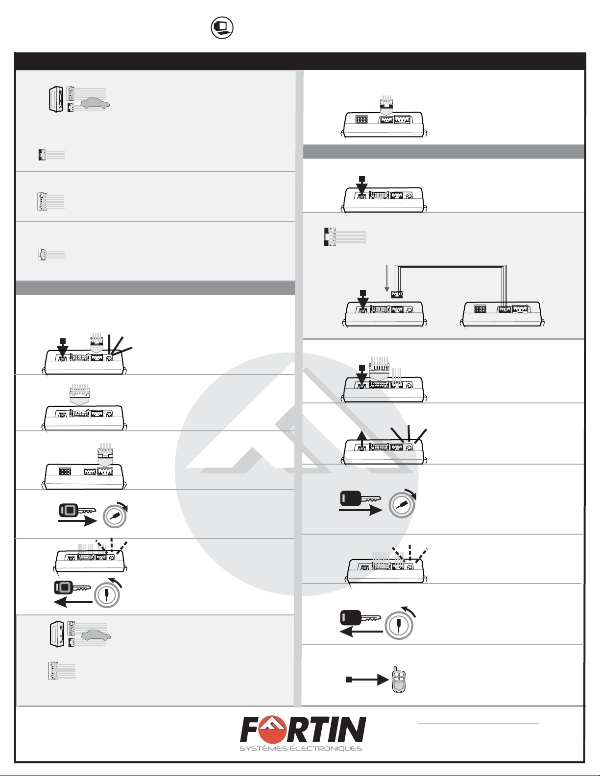
Starter or alarm
Data Link Port
Red | Rouge +12V
Black | Noir
Cut off one plug of
the Data-Link
connector, connect
the red wire to
+12V and the
black wire to
ground.
Back of the module
Dos du module
INSTALLATION WITH DATA-LINKINSTALLATION WITH DATA-LINK
INSTALLATION WITHOUT DATA-LINKINSTALLATION WITHOUT DATA-LINK
OR|OU
DATA-LINK
WIRING SCHEMATIC CONFIGURATION | SCHÉMA DE BRANCHEMENT
ÉTAPE 1
BRANCHEZ
PROGRAMMEZ
(Voir instruction
détaillé p.5)
ÉTAPE 2
BRANCHEZ AU VÉHICULE
BRANCHEZ DANS LE CAN
PROGRAMMEZ
(Voir instruction détaillé p.5)
P. 3
ÉTAPE 1
CONNECT
PROGRAM
(See detailled
instruction p.4)
ÉTAPE 2
CONNECT TO VEHICLE
CONNECT TO CAN
PROGRAM
(See detailled
instruction p.4)
Démarreur ou alarme
Starter or alarm
Démarreur ou alarme Coupez les 4 fils à l’extrémité
de l’un des deux connecteurs
Data-Link.
Connectez le fil rouge au
12V et le fil noir à la masse
du véhicule.
INSTALLATION SUR SYSTÈME AVEC DATA-LINKINSTALLATION SUR SYSTÈME AVEC DATA-LINK
INSTALLATION SUR SYSTÈME SANS DATA-LINKINSTALLATION SUR SYSTÈME SANS DATA-LINK
INSTALLATION GUIDE
Made in Canada - Rev. b - 15 / 11 / 2007
Web site: http://www.ifar.ca
DUO CAN 1

HONDA PROGRAMMING
CAN PROGRAMMING
2
3
7
8
11
12
13
14
2
IGN
START
OFF
IGN
START
OFF
16
15
1
1.C
1.B
5
3
2
IGN
START
OFF
IGN
START
OFF
1.A
4
1
6
Connector 1 (Black):
Connect the Data-Link connector directly in the CAN
module.
DATA-LINK
9
10 Back of the
module
Back of the
module
1
Connect the second Data-Link
connector in the CAN
(CONN. 4 Located at the back)
P. 4
Copyright © 2006 , FORTIN AUTO RADIO INC ALL RIGHTS RESERVED-2007
INSTALLATION AND PROGRAMMING INSTRUCTIONSINSTALLATION AND PROGRAMMING INSTRUCTIONS
Make the connections of the CAN to the
vehicle:
Connector 3 (White, located at the back of the module):
Make the connections associated with the vehicle in the
VEHICLE FIT GUIDE (P.3)
Connector 2 (White):
Make the connections associated with the vehicle in the
VEHICLE FIT GUIDE (P.3)
Connector 1 (Black):
Determine the type of installation:
DATA-LINK (See P.3)INSTALLATION WITH
INSTALLATION WITHOUT DATA-LINK (See P.3)
Press
CONN 1
the programming switch while
inserting the main wires harness
()
into the CAN module.
The LED will illuminate to indicate
you are in
programming mode, release the
programming button.
Connect
CONN. 2
the other connectors
()
WARNING: Connector 2 can be
easily plugged in backwards.
Connect
CONN. 3
the other connectors
()
Turn the key to the ."ON" position
Once the LED starts to flash rapidly
turn the key to the .
The LED will turn off to indicate the
module has been programmed.
OFF position
The module is now ready for use.
Make the connections of the HONDA to the
vehicle:
Connector 2 (White):
(I) Locate the wiring type for the vehicle on the
VEHICLE FIT GUIDE (P.3)
(II) Make the connections associated with the vehicle in the
WIRING SCHEMATIC CONFIGURATION (P.3)
Insert into the
interface.
connector 2
HONDA
Turn the
position.
Ignition to the ON
Remove the key and start the
vehicle using the remote
starter to ensure
functionality.
Turn the Ignition key to
OFF position.
The LED flashes 10 times,
the module is programmed.
Release the programming
button when the LED turns
ON.
Press and hold the programming
button.
LED Module Diagnostics :
On:
OFF:
Flash:
Bypass Activated
Not activated
Not programmed.
Neither the manufacturer or distributor of this module is
responsible of damages of any kind indirectly or directly
caused by this module, except for the replacement of this
module in case of manufacturing defects. This module must be
installed by qualified technician. This instruction guide may
change without notice. isit www.ifar.ca to get latest version.V
INSTALLATION GUIDE
Made in Canada - Rev. b - 15 / 11 / 2007
Web site: http://www.ifar.ca
CAN
CAN
CAN
CAN
CAN
CAN
HONDA
HONDA
HONDA
HONDA
HONDA
DUO CAN 1
PROGRAMMATION HONDA
2
3
Branchez le connecteur 2
(CONN. 2)
ATTENTION: Ne pas brancher le
connecteur à l'envers.
7
Effectuez les connexions du HONDA au
véhicule:
Connecteur 2 (Blanc):
Déterminez le type de branchement selon votre véhicule
(Voir P.3).
Effectuez les branchements selon le type d’installation
(Voir
GUIDE DES VOITURES,
SCHÉMA DE BRANCHEMENT, P.3).
Copyright © 2006 , FORTIN AUTO RADIO INC ALL RIGHTS RESERVED-2007
8
11
12
13
14
2
IGN
START
OFF
Maintenir le bouton de
programmation du HONDA
enfoncé.
Insérez le dans le
module
connecteur 2
HONDA.
Lorsque la DEL s’allume, relâchez
le bouton de programmation.
IGN
START
OFF
Retirez la clé du barillet et
démarrez le véhicule avec le
démarreur à distance.
16
Tournez la clef à OFF.
Le DEL clignote 10 fois.
Le module est programmé.
Tourner la clef en position ignition
(ON).
15
1
1.C
1.B
5
Branchez le connecteur 3
(CONN. 3)
3
2
IGN
START
OFF
IGN
START
OFF
Tournez la clef en position .ignition
1.A
4
1
INSTRUCTIONS D’INSTALLATION ET DE PROGRAMMATIONINSTRUCTIONS D’INSTALLATION ET DE PROGRAMMATION
Effectuez les connexions du CAN au véhicule:
Connecteur 3 (Blanc, situé au dos du module):
Déterminez le type de branchement selon votre véhicule
(Voir P.3)GUIDE DES VOITURES,
Effectuez les branchements selon le type d’installation
(Voir SCHÉMA DE BRANCHEMENT, P.3).
Connecteur 2 (Blanc):
Déterminez le type de branchement selon votre véhicule
(Voir P.3)GUIDE DES VOITURES,
Effectuez les branchements selon le type d’installation
(Voir SCHÉMA DE BRANCHEMENT, P.3).
Lorsque le DEL clignote
rapidement, tournez la clef en
position OFF.
Le DEL s'éteint pour indiquer
que le module est programmé.
6
Maintenez le bouton de
programmation enfoncé
connecteur 1
relâchez le bouton de
programmation.
en
insérant le dans le
CAN.
Le DEL s'allume pour indiquer le
début de la programmation,
Connecteur 1 (Noir):
Data-Link non Data-LinkDéterminez le type d’installation ( ou )
Pour l’installation Data-Link assurez vous de la présence du
connecteur Data-Link sur le démarreur. ( ).
Pour installation non Data-Link (P.3).
P.3
Connecteur 1 (Noir):
Branchez le connecteur Data-Link directement dans le
module CAN
DATA-LINK
Diagnostique du DEL du module
Allumé:
Éteint:
Flash:
Le module est activé.
Le module n'est pas activé.
Le module n'est pas programmé.
Neither the manufacturer or distributor of this module is
responsible of damages of any kind indirectly or directly
caused by this module, except for the replacement of this
module in case of manufacturing defects. This module must be
installed by qualified technician. This instruction guide may
change without notice. isit www.ifar.ca to get latest version.V
9
10 Dos du
module
Dos du module
1
Branchez le 2ieme connecteur
Data-Link dans le CAN
(CONN. 4 Situé au verso)
P. 5
GUIDE
Fabriqué au - 15 / 11 / 2007
http://www.ifar.ca
D’INSTALLATION
Canada - Rev. b
Site Internet:
CAN
CAN
CAN
CAN
CAN
HONDA
CAN
HONDA
HONDA
HONDA
HONDA
PROGRAMMATION CAN
DUO CAN 1

CAN MODULE Type 3
CAN SW: | Brun/NoirBrown/Black
Acura
Honda
TL
Ridgeline
Accord
Accord Hybrid
TSX
CAN SW: Brown/Black | Brun/Noir
CAN SW: Brown/Red
| Brun/Rouge
CAN SW: Brown/Red
| Brun/Rouge
CAN SW: Brown/Black
| Brun/Noir
VEHICLE DATA WIRE COLOR ! COULEUR DE FILS DATAVEHICLES | VEHICULES
Acura
Honda
MDX
RL
Odyssey
CAN SW: Green/Red
| Vert/Rouge
CAN SW: Green | Vert
CAN SW: Green | Vert
VEHICLES | VEHICULES VEHICLE DATA WIRE COLOR ! COULEUR DE FILS DATA
CAN MODULE Type 2CAN MODULE Type 1
Copyright © 2006 , FORTIN AUTO RADIO INC ALL RIGHTS RESERVED-2007
P. 6
WIRING SCHEMATIC CONFIGURATION | SCHÉMA DE BRANCHEMENT
(CAN SW) Data
Trunk Release
Unlock
Door Trigger
Hood Trigger
Ground Out
Trunk Trigger
Ignition
Lock
Tach Output
Defrost
Trunk release
Yellow
Unlock
Purple
Orange
Door Trigger
Blue
Hood Trigger
Pink
White
Lt. Blue
Yellow/Black
Ground Out
Trunk Trigger
14
81
7
Orange/Black
Green
Pink/Black
White/Black
Lt. Blue/Black
~
~
Ignition
Lock
Tach Output
Sliding Door Right
Sliding Door Left
Ignition Yellow
Purple
Orange
Blue
Pink
White
Lt. Blue
Yellow/Black
14
81
7
Orange/Black
Green
Pink/Black
White/Black
Lt. Blue/Black
Brown
Grey/Black
Grey
Brown/White
4
1
~
Brown
Grey/Black
Grey
Brown/White
4
1
Yellow
Purple
Orange
Blue
Pink
White
Lt. Blue
Yellow/Black
Purple/Black
14
81
7
Orange/Black
Green
Pink/Black
White/Black
Lt. Blue/Black
Data-Link (2 way)
Connect: Branchez:
Brown
Grey/Black
Grey
Brown/White
4
1
Yellow
Purple
Orange
Blue
Pink
White
Lt. Blue
Yellow/Black
Purple/Black
14
81
7
Orange/Black
Green
Pink/Black
White/Black
Lt. Blue/Black
Data-Link (1 way)
Connect: Branchez:
Brown
Grey/Black
Grey
Brown/White
4
1
Yellow
Purple
Orange
Blue
Pink
White
Lt. Blue
Yellow/Black
Purple/Black
14
81
7
Orange/Black
Green
Pink/Black
White/Black
Lt. Blue/Black
Data-Link (2 way)
Connect: Branchez:
Brown
Grey/Black
Grey
Brown/White
4
1
Yellow
Purple
Orange
Blue
Pink
White
Lt. Blue
Yellow/Black
Purple/Black
14
81
7
Orange/Black
Green
Pink/Black
White/Black
Lt. Blue/Black
Data-Link (1 way)
Connect: Branchez:
Wires located in driver kick panel, PIN-4, bottom row of 21-pin GREEN plug.
Fils situés dans le panneau latéral du côté chauffeur, PIN-4, dernier rang de la connecteur vert de 21 PINS.
N.C.
N.C.
N.C.
N.C.
N.C.
Wires located in driver kick panel, PIN-4, bottom row of 21-pin GREEN plug.
Fils situés dans le panneau latéral du côté chauffeur, PIN-4, dernier rang du connecteur vert de 21 PINS.
~
Purple/Black or Purple/White Purple/Black or Purple/White
N.C.
N.C.
N.C. N.C.
N.C.
Ni le manufacturier, ni le distributeur ne se considèrent responsables des
dommages causés ou ayant pu être causés, indirectement ou directement,
par ce module, excepté le remplacement de ce module en cas de défectuosité
de fabrication. Ce module doit être installé par un technicien qualifié. Ce guide
d'instruction peut faire l’objet de changement sans préavis. Consultez le
www.ifar.ca pour voir la plus récente version.
INFORMATIONS
Ni le manufacturier, ni le distributeur ne se considèrent responsables des
dommages causés ou ayant pu être causés, indirectement ou directement,
par ce module, excepté le remplacement de ce module en cas de
défectuosité de fabrication. Ce module doit être installé par un technicien
qualifié. Ce guide d'instruction peut faire l’objet de changement sans préavis.
Consultez le www.ifar.ca pour voir la plus récente version.
INSTALLATION GUIDE
Made in Canada - Rev. b - 15 / 11 / 2007
Web site: http://www.ifar.ca
(CAN Low) Data
Brown
Grey/Black
Grey
Brown/White
4
1
(CAN High) Data
Brown
Grey/Black
Grey
Brown/White
4
1
Yellow
Purple
Orange
Blue
Pink
White
Lt. Blue
Yellow/Black
Purple/Black
14
81
7
Orange/Black
Green
Pink/Black
White/Black
Lt. Blue/Black
Data-Link (2 way)
Connect: Branchez:
Brown
Grey/Black
Grey
Brown/White
4
1
Yellow
Purple
Orange
Blue
Pink
White
Lt. Blue
Yellow/Black
Purple/Black
14
81
7
Orange/Black
Green
Pink/Black
White/Black
Lt. Blue/Black
Data-Link (1 way)
Connect: Branchez:
N.C.
Yellow
Unlock
Purple
Orange
Door Trigger
Blue
Pink
White
Lt. Blue
Yellow/Black
Ground Out
Trunk Trigger
14
81
7
Orange/Black
Green
Pink/Black
White/Black
Lt. Blue/Black
~
~
Ignition
Lock
Tach Output Hood Trigger
N.C.
N.C.
N.C.
N.C.
N.C.
N.C.
12 56 7
Wires located at steering
column immobilizer control unit
Fils situés à la colonne de
direction au module de contrôle
de la clé à puce
34
Pink
Blue
Purple/Black or Purple/White
Trunk Release
Fuse Panel
Panneau à fusibles
(CAN SW) Data Brown
Grey/Black
Grey
Brown/White
4
1
N.C.
N.C.
N.C.
Fuse Panel
Panneau à fusibles
21 20 19 18 17 16 15 14 13 12 11 10
98 76 5 32 14
21 20 19 18 17 16 15 14 13 12 11 10
98 76 5 32 14
DUO CAN 1

HONDA MODULE Type 6
HONDA MODULE Type 5
HONDA MODULE Type 4
Light Green Pin #6
Vert Pâle Pin #6
Yellow
Jaune
Data Synchro Security Lamp Ground
WIRE COLORS | COULEURS DE FILS
Ignition 12V
VEHICLES | VEHICULES
Honda
Accord
MDX Small Light Green Pin #3
Petit vert pâle Pin #3 Brown
Brun
Data Synchro Security Lamp Ground
WIRE COLORS | COULEURS DE FILS
Ignition 12V
VEHICLES | VEHICULES
Acura
Acura
Honda
Data Synchro Security Lamp Ground
Red/Blue Pin #6
Rouge/Bleu Pin #6
Red/Blue Pin #6
Rouge/Bleu Pin #6
Red/Blue Pin #6
Rouge/Bleu Pin #6
Red/Blue Pin #6
Rouge/Bleu Pin #6
Red/Blue Pin #6
Rouge/Bleu Pin #6
Blue/Orange Pin #3
Bleu/Orange Pin #3
Blue/Orange Pin #3
Bleu/Orange Pin #3
Blue/Orange Pin #3
Bleu/Orange Pin #3
Blue/Orange Pin #3
Bleu/Orange Pin #3
Blue/Orange Pin #3
Bleu/Orange Pin #3
Brown/Yellow Pin #7
Brun/Jaune Pin #7
Brown/Yellow Pin #7
Brun/Jaune Pin #7
Brown/Yellow Pin #7
Brun/Jaune Pin #7
Black Pin #1
Noir Pin #1
Brown/Yellow Pin #7
Brun/Jaune Pin #7
TL
TSX
Accord
Odyssey
Ridgeline
WIRE COLORS | COULEURS DE FILS
Ignition
Yellow/Black
Jaune/Noir
Yellow/Black
Jaune/Noir
Black/Yellow
Noir/Jaune
Yellow/Black
Jaune/Noir
Green/Black
Vert/Noir
12V
White Pin #1
White Pin #1
White Pin #1
White Pin #1
RL Light Green Pin #6
Vert pâle Pin #6
Pink
Rose Red Pin #3
Rouge Pin #3
VEHICLES | VEHICULES
VEHICLE FIT GUIDE | GUIDE DES VEHICULES
N.C.
N.C.
Data
7 pin conn.
N.C.
Data
Ignition
Ignition
Security Lamp out | Lumière sécurité Out
Yellow/Black | Jaune/Noir
Yellow | Jaune
Purple/White | Mauve/Blanc
Purple | Mauve
Security Lamp in | Lumière sécurité In
Green | Vert
Blue | Bleu
Orange/Black | Orange/Noir
Orange | Orange
N.C.
N.C.
Ignition
Data
7 pin conn.
N.C.
754 1632
N.C.
Security Lamp
Data
N.C.
(-) While running | Masse d'activation
(-) While running | Masse d'activation
Ignition
1 456723
N.C.
N.C.
N.C.
Data
N.C.
N.C.
Ignition
1 345 726
Data
Ignition
(-) While running | Masse d'activation
7 pin conn.
GUIDE
Fabriqué au - 15 / 11 / 2007
http://www.ifar.ca
D’INSTALLATION
Canada - Rev. b
Site Internet:
Copyright © 2006 , FORTIN AUTO RADIO INC ALL RIGHTS RESERVED-2007
Yellow/Black | Jaune/Noir
Yellow | Jaune
Purple/White | Mauve/Blanc
Purple | Mauve
Green | Vert
Blue | Bleu
Orange/Black | Orange/Noir
Orange | Orange
Yellow/Black | Jaune/Noir
Yellow | Jaune
Purple/White | Mauve/Blanc
Purple | Mauve
Green | Vert
Blue | Bleu
Orange/Black | Orange/Noir
Orange | Orange
P. 7
DUO CAN 1
Table of contents
Languages:
Other Fortin Remote Starter manuals

Fortin
Fortin EVO-ONE FTX25 User manual

Fortin
Fortin FTX84-1W User manual

Fortin
Fortin EVO ALL User manual

Fortin
Fortin RM442 User manual

Fortin
Fortin EVO-ALL User manual

Fortin
Fortin EVO ONE User manual

Fortin
Fortin 12971 User manual

Fortin
Fortin FS 105 User manual

Fortin
Fortin KEY-OVERRIDE-ALL User manual

Fortin
Fortin E400 RF442W User manual

Fortin
Fortin E400 RF642W User manual

Fortin
Fortin EVO-ONE User manual

Fortin
Fortin E400 RF751W User manual

Fortin
Fortin EVO-ONE FTX75 User manual

Fortin
Fortin EVO ONE User manual

Fortin
Fortin FTX-44-2W User manual

Fortin
Fortin E400 RF441W User manual

Fortin
Fortin EVO-ONE RFK942 User manual

Fortin
Fortin INT-SL User manual

Fortin
Fortin EVO ONE User manual


