1
1
O
Ov
ve
er
rv
vi
ie
ew
ws
s....................................................................................................................................................2
1.1 Key Features......................................................................................................................................2
1.2 Read Before Use................................................................................................................................3
1.3 Packing Contents...............................................................................................................................3
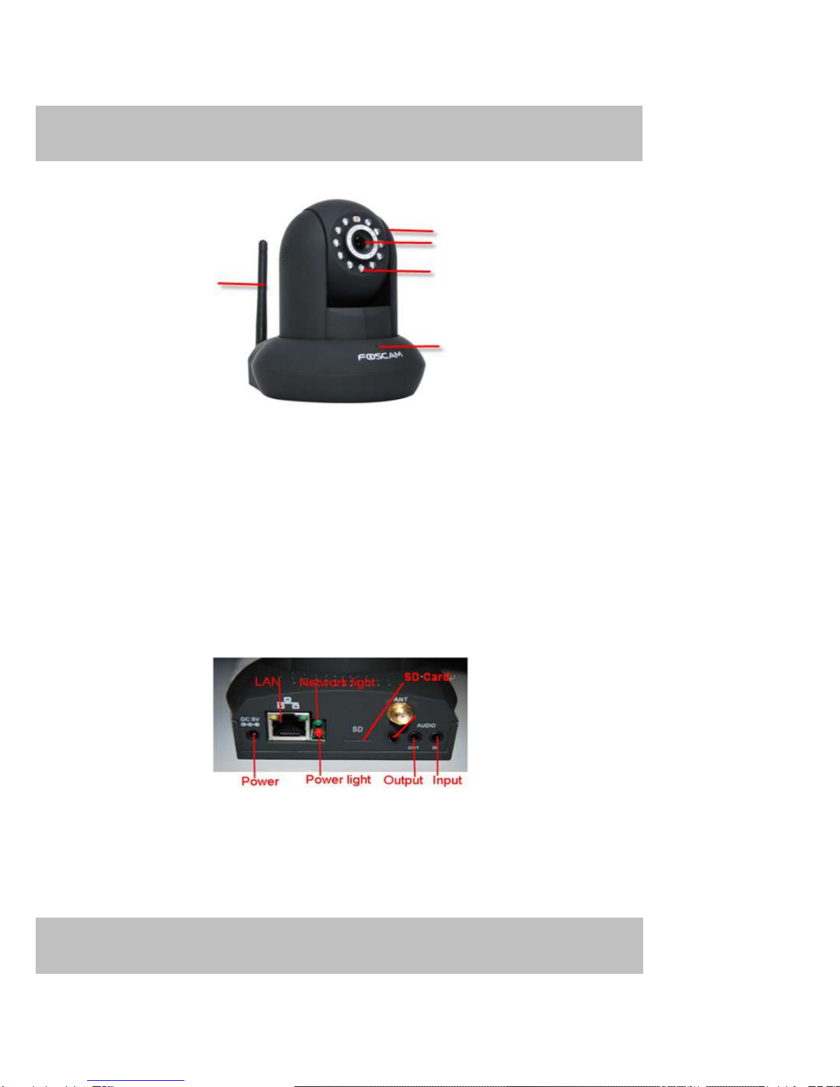
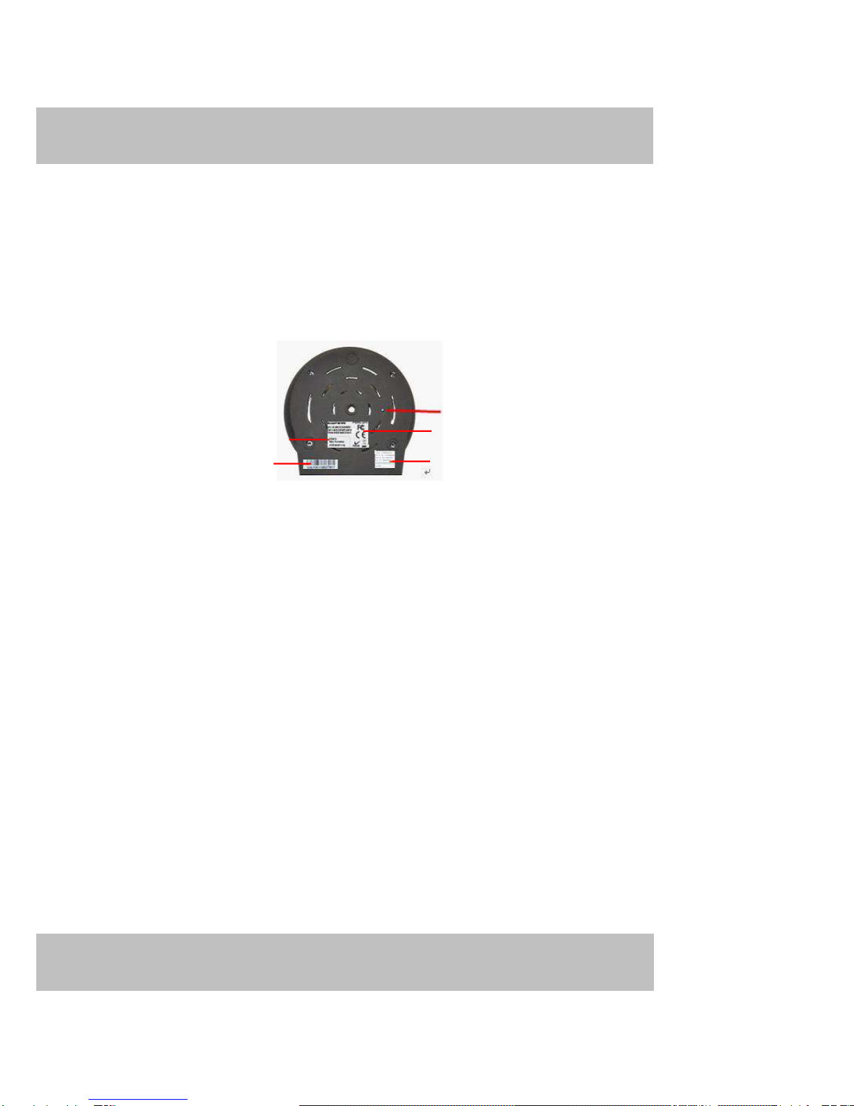
1.4 Physical Description...........................................................................................................................3
1.5 SD Card............................................................................................................................................. 5
2
2
A
Ac
cc
ce
es
ss
si
in
ng
g
t
th
he
e
N
Ne
et
tw
wo
or
rk
k
C
Ca
am
me
er
ra
a...................................................................................................................6
2.1 Access the Camera in LAN.................................................................................................................6
2.2 Access the Camera in WAN ...............................................................................................................9
2.3 Using the VLC player....................................................................................................................... 14
3 Surveillance Software GUI ......................................................................................................................... 17
3.1 Login Window................................................................................................................................... 18
3.2 Surveillance Window........................................................................................................................ 20
4 Advanced Camera Settings........................................................................................................................ 28
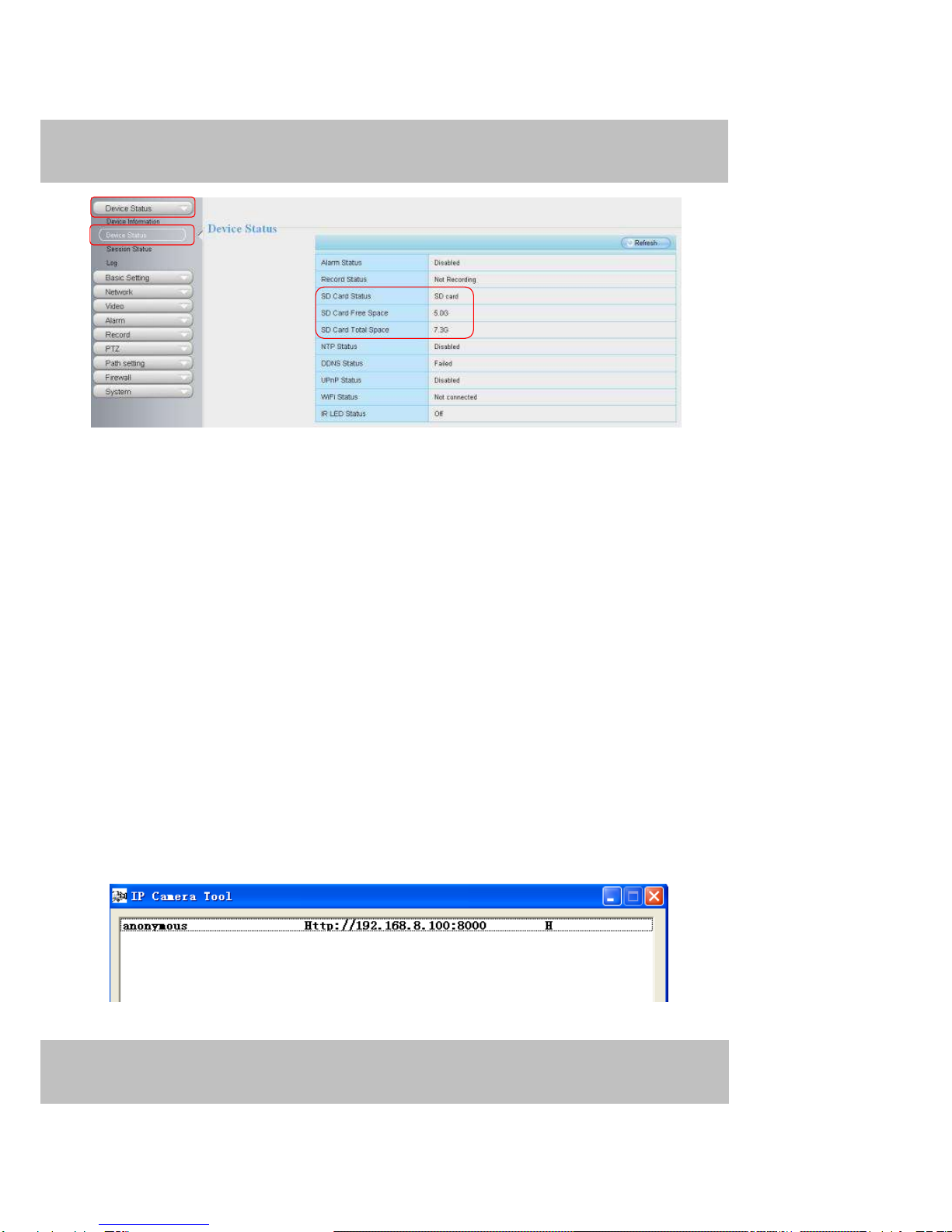
4.1 Device Status................................................................................................................................... 28
4.2 Basic Settings .................................................................................................................................. 30
4
4.
.3
3
N
Ne
et
tw
wo
or
rk
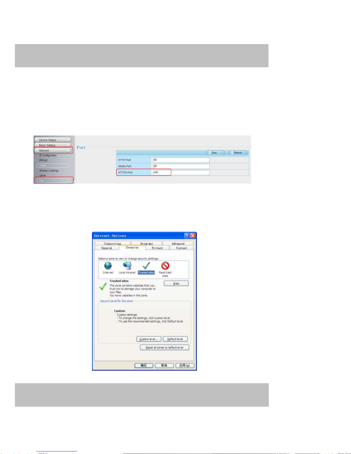
k............................................................................................................................................ 41
4.4 Video................................................................................................................................................ 58
4.5 Alarm................................................................................................................................................ 61
4.6 Record............................................................................................................................................. 65
4.7 Pan/Tilt............................................................................................................................................. 66
4.8 Path Settings.................................................................................................................................... 70
4.9 Firewall............................................................................................................................................ 71
4.10 System........................................................................................................................................... 71
5 Playback.................................................................................................................................................... 75
6 Phone APPs............................................................................................................................................... 76
6.1 APPfor Android cell phones............................................................................................................. 76
6.2 APPfor iPhones............................................................................................................................... 84
7 APPENDIX................................................................................................................................................. 92
7.1 FrequentlyAsked Questions............................................................................................................. 92
7.2 Default Parameters .......................................................................................................................... 97
7.3 Specifications................................................................................................................................... 97
7.4 CE & FCC.......................................................................................................................................... 99
7.5 WARRANTY..................................................................................................................................... 99
8 OBTAINING TECHNICAL SUPPORT ........................................................................................................102