Foster EcoPro G2 Series User manual

By Appointment to
Her Majesty Queen Elizabeth II
Suppliers of Commercial Refrigeration
Foster Refrigerator, King’s Lynn
A Division of ITW Ltd
Foster Refrigerator,
Oldmedow Road,
King’s Lynn,
Norfolk, PE30 4JU
United Kingdom
ISO 9001 ISO 14001
Original Service Manual
EcoPro G2 Range
Cabinet & Counter Models
FD1-11 & FD1-14 Controller
Version 3
English
Reduced Width Counter Models
FD2-10 Controller & LCD5S Display

1
Contents Page
Manual Information & Health & Safety Notes
Environmental Management Policy
Disposal Requirements & Electrical Safety
EcoPro G2 Cabinet Description
Display Icons & Switches
Start up, Standby, User Adjustments
Temperature Sensitivity, Key Security, Light Function, Downloading, Defrost Function &
Reduced Energy Control.
FD1-11 Controller Connection Drawing, Technical Data & Conguration of Parameters
Default Parameters Explained
Individual EcoPro G2 Cabinet Parameter Values
Technical Data
Wiring Diagrams
Troubleshooting & Notes
Service Manual Information:
The products and all information in this manual are subject to change without prior notice.
We assume by the information given that the person(s) working on these refrigeration units are
fully trained and skilled in all aspects of their workings. Also that they will use the appropriate safety
equipment and take or meet precautions where required.
The service manual does not cover information on every variation of this unit; neither does it cover the
installation or every possible operating or maintenance instruction for the units.
Health & Safety Warnings & Information
Make sure the power supply is turned off before making any electrical repairs.
To minimise shock and re hazards, please do not plug or unplug the unit with wet
hands.
During maintenance and cleaning, please unplug the unit where required.
Care must be taken when handling or working on the unit as sharp edges may
cause personal injury, we recommend the wearing of suitable PPE.
Ensure the correct moving and lifting procedures are used when relocating a unit.
Do NOT use abrasive cleaning products, only those that are recommended. Never
scour any parts of the refrigerator. Scouring pads or chemicals may cause damage
by scratching or dulling polished surface nishes.
Failure to keep the condenser clean may cause premature failure of the motor/
compressor which will NOT be covered under warranty policy.
Do NOT touch the cold surfaces in the freezer compartment. Particularly when
hands are damp or wet, skin may adhere to these extremely cold surfaces and
cause frostbite.
Please ensure the appropriate use of safety aids or Personnel Protective Equipment
(PPE) are used for you own safety.

2
Environmental Management Policy
Product Support and Installation Contractors.
Foster Refrigerator recognises that its activities, products and services can have an adverse impact upon the
environment.
The organisation is committed to implementing systems and controls to manage, reduce and eliminate its adverse
environmental impacts wherever possible, and has formulated an Environmental Policy outlining our core aims.
A copy of the Environmental Policy is available to all contractors and suppliers upon request.
The organisation is committed to working with suppliers and contractors where their activities have the potential
to impact upon the environment. To achieve the aims stated in the Environmental Policy we require that all
suppliers and contractors operate in compliance with the law and are committed to best practice in environmental
management.
Product Support and Installation contractors are required to:
1. Ensure that wherever possible waste is removed from the client’s site, where arrangements are in place all
waste should be returned to Foster Refrigerator’s premises. In certain circumstances waste may be disposed of
on the client’s site; if permission is given, if the client has arrangements in place for the type of waste.
2. If arranging for the disposal of your waste, handle, store and dispose of it in such a way as to prevent its escape
into the environment, harm to human health, and to ensure the compliance with the environmental law. Guidance
is available from the Environment Agency on how to comply with the waste management ‘duty of care’.
3. The following waste must be stored of separately from other wastes, as they are hazardous to the environment:
refrigerants, polyurethane foam, and oils.
4. When arranging for disposal of waste, ensure a waste transfer note or consignment note is completed as
appropriate. Ensure that all waste is correctly described on the waste note and include the appropriate six-digit
code from the European Waste Catalogue. Your waste contractor or Foster can provide further information if
necessary.
5. Ensure that all waste is removed by a registered waste carrier, a carrier in possession of a waste management
licence, or a carrier holding an appropriate exemption. Ensure the person receiving the waste at its ultimate
destination is in receipt of a waste management licence or valid exemption.
6. Handle and store refrigerants in such a way as to prevent their emission to atmosphere, and ensure they are
disposed of safely and in accordance with environmental law.
7. Make arrangements to ensure all staff who handle refrigerants do so at a level of competence consistent with the
City Guilds 2079 Handling Refrigerants qualication or equivalent qualication.
8. Ensure all liquid substances are securely stored to prevent leaks and spill, and are not disposed of into storm
drains, foul drain, or surface water to soil.
Disposal Requirements
If not disposed of properly all refrigerators have components that can be harmful to the environment.
All old refrigerators must be disposed of by appropriately registered and licensed waste contractors,
and in accordance with national laws and regulations.
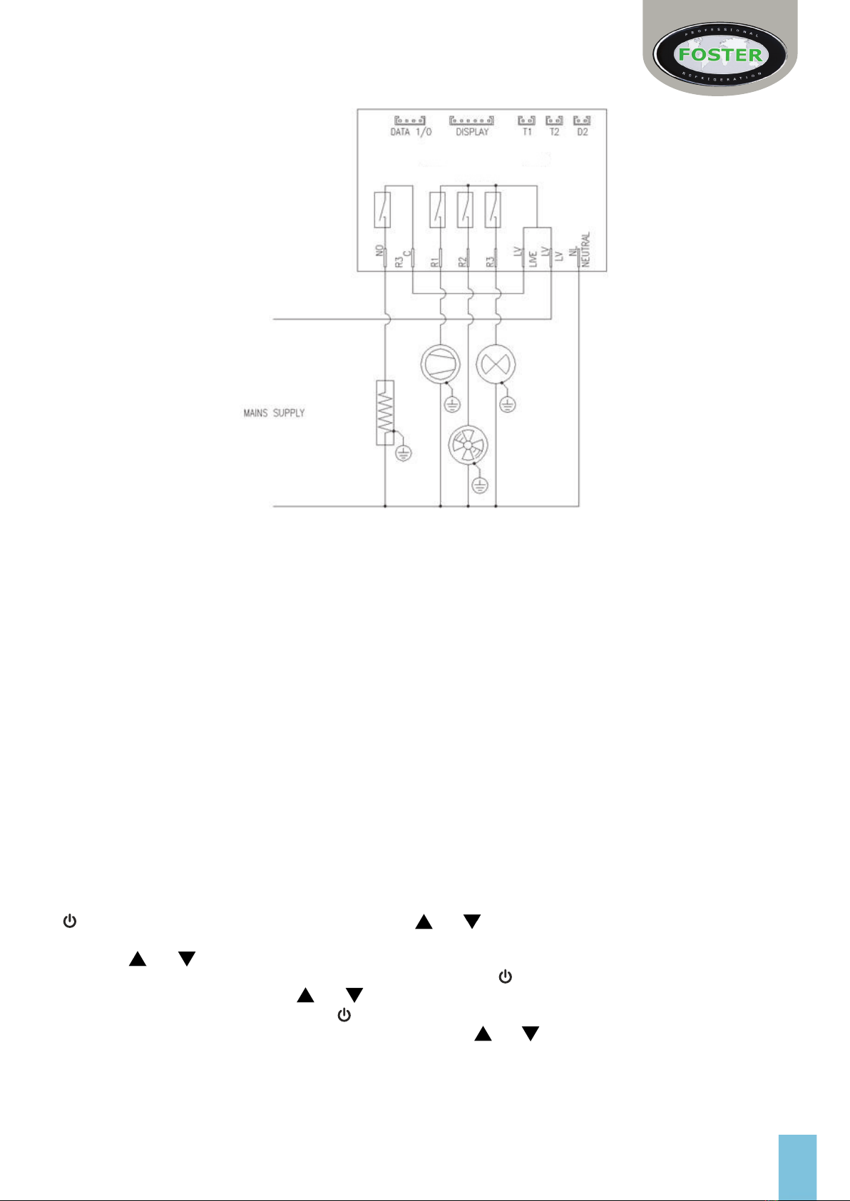
General Electrical Safety
Foster Refrigerator recommends that the equipment is electrically connected via a Residual Current Device; such as
a Residual Current Circuit Breaker (RCCB) type socket, or through a Residual Current Circuit Breaker with Overload
Protection (RCBO) supplied circuit.

3
Cabinets & Counters with FD1-11 and FD1-14 Controller
Start-Up and Operation
Initial Set Up
After unpacking clean and allow the cabinet to stand for 2 hours before turning on.
Ensure the cabinet is situated where neither hot nor cold air sources will affect its performance. Make sure that
a minimum clearance of 310mm above and 50mm around the cabinet is available for ventilation and effective
operation.
Initial Start up
Connect the unit to a suitable mains power outlet and turn the supply on. Please do not plug or unplug the unit with
wet hands.
The cabinet will energise briey showing followed by the power switch slowly pulsing with a blank display. The
unit is now in standby.
(Some icons or switches are only visible during adjustment, when activated by parameters or through operation/
manual selection).
For all Reduced Width Counters please see controller
information on page 13.
Cabinet Version
Keypad Lock Warning/ Alarm
Service Mode Temperature Setting
Compressor Function Defrost Function
Evaporator Fan Function Reduced Energy Mode
Data Download Switch Light Switch
Decrease Switch Increase Switch
Power Switch
Counter Version
Function Icons Temperature Display

4
Standby
Pressing this switch for 3 seconds will turn the unit on (the switch backlight is static and the display shows the
operating temperature) or put into standby (the switch backlight pulses slowly on & off).
As the operating temperature has been pre-set no adjustments are required. Allow the cabinet to reach its normal/
set operating temperature before loading.
User Adjustment Mode
You are required to enter this mode to make any setup changes.
These include Set Point, Keypad Security and display of T1, 2 or 3 probe temperatures.
Press and immediately release after which the and switches will ash/pulse together.
Press to scroll through the following screens:
To exit this mode scroll back to the adjustment screen and press or wait for 30 seconds and the display will revert
to the normal display showing the operating temperature.
Set Point and Other Mode Adjustments
Access the adjustment mode as described above. Using the or switches to scroll to the mode that requires
adjustments i.e ‘Set Point’ this is the minimum temperature the cabinet is allowed to cool down to (the display shows
the temperature and ash/pulsing icon ).
To adjust this press and release the icon will show constantly. Adjust the setting with the or switch. Conrm
the change by pressing and releasing again, the next mode will automatically show. Scroll through the modes with
the or switch until you return to the adjustment screen and press and release to exit and save.
If at any point the display is left for 30 seconds it will revert to the normal display and no
changes will be saved.
Increased Sensitivity of Temperature Settings
If you require the cabinet to have a more accurate or increased sensitivity to temperature and the warnings this
controls, the controller is able to measure temperature in 1/10ths of a degree (0.1°) instead of whole degrees.
With parameter ‘SC’ set to ‘1C’ the display will show the temperature as 1/10ths of a degree on the scale between
-9.9°C to +9.9°C.
Also, with parameter ‘SC’ set to ‘1F’ the controller has the facility to show the temperature in Fahrenheit (between
-58°F to 99°F). However if this is selected all other temperature related parameter values will have to be set
accordingly to this change. (See ‘Conguration of Parameters’ for information on how to access this).
Keypad Security Settings
Access the ‘Keypad Security’ screen as described above.
The screen will show the current status, initially preset to ‘ ’, with ashing. Press and release and will
show constantly. (If you modify this setting with to show ‘ ’ the keypad will be locked, will show constantly
and the cabinet will not be able to be put into standby, carry out a manual defrost, adjust temperature set point,

5
download data or switch on/off the units lights. To conrm any change you must press again so the next screen
‘ ’ shows).
Exit any of the ‘Adjustment Modes’ as described above.
Internal Light (where tted)
To switch on the lights press and release so that the switch backlight is on continuously.
To switch off press and release and the switch backlight will ash/pulse.
Downloading Data
This option is only available when enabled via parameters and the cabinet has the additional FCOM1 device
available –this availability will be shown by the data switch being constantly illuminated.
To download the data the switch should be pressed and then released. The information will then begin
downloading to the appropriate printer or PC and the backlight of the switch will ash. On completion the switch will
return to constant state of illumination.
Defrost
All Foster G2 cabinets are tted with a fully automatic defrost system to ensure that the evaporator coil remains
free from ice during normal use. Melt-water is evaporated using either the heat from the refrigeration system or a
separate electric heater (dependent upon model and conguration).
To activate a manual defrost – while the cabinet is in ‘run’ mode press and hold for 5 seconds. After 3 seconds
the display will go blank then return after a further 2 seconds. At this point a defrost will be performed (subject to
underlying operating parameters), this will terminate automatically.
Reduced Energy Control Mode
The reduced energy control mode (‘e’ mode) detects when the unit has reached the selected temperature set-point
and the operating conditions (such as usage rate) have become less demanding.
When enabled, the controller will modify the compressor, evaporator fan and defrost operation in order to reduce the
energy consumed. During the reduced energy control mode is illuminated at the bottom right corner of the display.
Upon an increase in operating demand the controller reverts back to the standard operating settings with the
symbol extinguished. The ‘e’ mode is enabled by setting parameter ‘iiM’ to ‘Au’. Further parameter settings (‘iiS’,
‘iit’, ‘iiP’, ‘iiY’, ‘iiF’, ‘iid’, and ‘iiE’) control the temperature cycle during the reduced energy control mode. Setting
parameter ‘iiM’ to ‘no’ disables the ‘e’ mode.

6
FD1-11 and FD1-14 Controller Connection Drawing
Conguration of Parameters
Parameters should not be changed unless you have an understanding of their purpose and the following
instructions are fully understood.
> To gain access to the parameters use the ‘Adjustment Mode’. This is accessed by pressing and releasing the
switch. After selecting this mode press and hold and together for 5 seconds. The rst parameter will
show on the display.
> Using the and switches you can scroll through all parameters and their values.
> If you wish to change a parameter value press and release the switch when one the desired mnemonic.
Once selected in this way use the and switches to modify. When the new required value is shown it will
be saved by pressing and releasing the switch. After which the display will show the next parameter.
> To exit this mode or revert to normal operating mode, press and together then release.
If at any point no buttons are pressed for 30 seconds without saving a new value the display will return to the
standard temperature display without changes being made.
FD1-11 and FD1-14 Technical Data
Power Supply
FD1-11
230Vac±10%,
50/60Hz, Operating 3.2W, Standby 0.9W
Relay Output
Compressor - 16(8) A 240Vac
Defrost - 16(4) A 240Vac
Evap. Fan - 16(4) A 240Vac
Auxiliary Loads 1 - 8(2) A 240Vac
Input
NTC 10KΩ@25°C
Measurement Range
-50…120°C, -55…240°F
-50 / -9.9…19.9 / 80°C (NTC 10K Only)
Measurement Accuracy
<0.5°C within the measurement range
CE (Reference norms)
EN60730-1; EN60730-2-9
EN55022 (Class B)
EN50082-1

7
EcoPro G2 FD1-11 & FD1-14 Controller Default Parameter Values
Para
Condition
Range Description Dim
FD1-11
FD1-14
SL -50 … SH Minimum limit for ‘SP’ setting °C 1 1
SH SL … 90° Maximum limit for ‘SP’ setting °C 3 3
SP SL … SH Temperature set point to be achieved °C 1.5 1.5
CH RF – HE Refrigeration or Heating control mode Flag RF RF
HY 1 … 9.9° Off/On thermostat differential °K 3 3
CR 0 … 30min Compressor rest time Min 2 2
C1 0 … 30min Thermostat run times with faulty T1 probe (‘C1’ = 0
output with faulty T1 will always be off). Min 6 6
C2 0 … 30min Thermostat off time with faulty T1 probe (‘C2’ = ‘0’ &
‘C1’ => ‘0’output with faulty T1 will always be on.) Min 4 4
CS 0 … 30min Compressor stop delay after door has been opened
(only if ‘DS’ – ‘1’) Min 1 1
DM
Defrost start mode:
Func. TM TM
NO Defrost is disabled (the following parameter will be ‘FM’)
TM Regular time defrost
FR Defrost time elapses only in condition of frost
accumulation
DB
Only if ‘DM’ = ‘TM’ or ‘FR’
0 … 90 Hrs Time interval between defrosts Hrs. 6 6
DF
Defrost timer clock:
Flag YS YSYS Following mains interruption, timer resumes count
NO Following mains interruption, timer restarts from zero
DL -50 … 90° Defrost end temperature (only if ‘T2’ = ‘1’) °C 15 15
DT 1 … -0min Maximum defrost duration Min 20 20
DY
Defrost type:
Func. OF OF
OF Timed off cycle defrost (compressor and heater off)
EL Electric heater defrost (compressor off, heater on).
GS Hot gas defrost (compressor and heater on)
DS
Defrost synchronisation:
Func. HI HI
OF No synchronisation (defrost occurs immediately when
scheduled).
LO Defrost waits until T1 = lowest part of cycle (when
compressor would normally ‘cut-off’).
HI Defrost waits until T1 = highest part of cycle (when
compressor would normally ‘cut-in’).
ST 0 … 30min Defrost synchronisation time out when ‘DS’ = ‘LO’ to
provide maximum time defrost can be deferred. Min 5 5
DP 0 … 90sec Evaporator pump down. Timed pause at start of defrost Sec 0 0

8
DR
Only if ‘DM’ = ‘TM’ or ‘FR’
0 … 20sec
Defrost Pressure Reduction. At the end of a defrost,
time compressor continues running after hot gas
solenoid valve shuts.
Sec
N/A
FD1-14
Only
3
DN 0 … 30min Drain down period Min 1 1
DD
Defrost display mode:
Func. SP SP
RT Real (actual) air temperature
LT Last temperature display before start of defrost
SP The current set point value
DF Display will show ‘dp’.
DH 0 … 60min Defrost display delay period. Time ‘DD’ is shown
following defrost termination. Min 3 3
FD
Fans in defrost:
Flag YS YSYS Fans run during defrost
NO Fans do not run during defrost
FR -50 … 90° Evaporator fan restart temperature following defrost.
(Only if ‘T2’ = ‘1’). °C 5 5
FS 0 … 90min Maximum evaporator fan stop period defrost (only when
‘T1’ = ‘1’). Min 3 3
FM
Evaporator fan mode during thermostatic control:
Func. TM TM
NO Fan(s) run continuously (subject to door & defrost).
TP Temperature based control. When compressor is on,
fans are on.
TM
When compressor is off, fans run as long as
temperature difference Te-Ta > ‘FT’. Fans on again with
‘FH’.
FT -9.9 … 0° Te-Ta difference for fans to turn off after compressor
stopped. (Only if ‘T2’ – ‘YS’ and ‘FM’ = ‘TM’) °K -1 -1
FH 1 … 9.9° Temperature differential for evaporator fan restart (Only
if ‘T2’ – ‘YS’ and ‘FM’ = ‘TM’) °K 3 3
F1 0 … 90sec Evaporator fan stop delay after compressor stop Sec 10 10
F2 0 … 90sec Timed fan stop following ‘F1’ (With F2 = ‘0’ the fans
remain on all the time). Sec 60 60
F3 0 … 90sec Timed fan start following ‘F2’ (With F3 = ‘0’ & F2 > 0 the
fans remain off all the time). Sec 30 30
FP 0 … 90sec Minimum evaporator fan stop period (following door
opening etc.). Sec 20 20
AT
Alarm threshold conguration:
Func. RL RL
NO All temperature alarms are inhibited (the following
parameter will be ‘AO’).
AB The value set in ‘AL’ & ‘AH’ represent actual alarm set
points
RL
The values set in ‘AL’ & ‘AH’ are alarm differentials
which relate to ‘SP’ and ‘SP’ + ‘HY’ (the following
parameter will be ‘LD’)
AL
Only if
‘AM’ =
‘AB’
-50 … 90° Low temperature alarm threshold °C -3 -3
AH -50 … 90° High temperature alarm threshold (the following
parameter will be ‘AI’). °C 8 8

9
LD
Only if
‘AM’ = ‘RL’
-9.9 … 0° Low temperature differential (With ‘LD’ = ‘0’ the low
temperature alarm is excluded) °K -5 -5
HD 0 … 9.9° High temperature differential (With ‘HD’ = ‘0’ the low
temperature alarm is excluded). °K 5 5
AI
Only if ‘AM’ = ‘AB’ or
‘RL’
Alarm Probe:
Func. T1 T1
T1 Air temperature probe used for alarm detection
T2 Evaporator temperature probe used for alarm detection
(if ‘T2’ = ‘YS’).
T3 Third temperature probe used for alarm detection (if
‘D2’ = ‘T3’).
AD 0 … 90min Delay before alarm temperature warning Min 90 90
AO 0 … 30min Delay before door open alarm warning (only when ‘D1’
or ‘D2’ = ‘DS’) Min 5 5
PF 0 … 30° Power failure alarm differential. (With ‘PF’ = ‘0’ power
failure alarm is disabled). °K 10 10
AM
Operation in case of high condenser alarm (if
‘D2’=‘T3’ and ‘T3’=‘CD’):
Func. NO NO
NO High condenser temperature alarm inhibited
AP Condenser warning – ‘HC’ displayed, alarm sounds,
operation continues.
ST As ‘AP’ above, but compressor stopped (R1 de-
energised) and defrosts suspended.
AS
Only if
‘D2’ =
‘T3’
-50 … 90° Condenser alarm temperature °C 65 65
AF
Operation in case of high pressure alarm (if ‘D2’ =
‘HP’):
Func. ST ST
AP Pressure warning – ‘HP’ displayed, alarm sounds,
operation continues.
ST As ‘AP’ above, but compressor stopped (R1 de-
energised) and defrosts suspended.
SA All relays de-energised while condition exists.
AC 0 … 52
wks.
Condenser cleaning period. (With ‘AC’ = ‘0’ condenser
cleaning alarm is disabled) Wks. 0 0
IIM
Switchover method to reduced energy mode:
Func. AU AU
NO Reduced energy model is excluded (the following
parameter will be ‘DC’).
AU Reduced energy mode is activated/ de-active
automatically via ‘IIS’ and ‘IIT’
D2 Second parameter set activated by ‘D2’ input (‘D2’ =
‘IIM’)

10
IIS
Only if ‘IIM’ = ‘AU’ or ‘D2’
1 … 90min Minimum ‘non activity’ time for reduced energy mode Min 20 20
IIT 1 … 10° Maximum temperature ‘addition’ for reduced energy
mode °C 6 6
IIP 1 … 50°
Reduced energy mode temperature set point –
differential above ‘SP’ (refrigerating) below ‘SP’
(heating).
°K 2 2
IIY 1 … 10° Reduced energy mode ‘off/on’ thermostat differential. °K 3 3
IIF
Evaporator fan control during ‘Reduced Energy’
operation:
Func. TM TM
NO Fan(s) run continuously
TP
Temperature based control. When compressor is on,
fans are on. When compressor is off, fans run as long
as temperature difference Te-Ta > ‘FT’. Fans on again
with ‘FH’.
TM
Time based control. When compressor is on, fans are
on. When compressor is off, fans in accordance to
parameters ‘F1’, ‘F2’ and ‘F3’.
IID 0 … 90 Hrs Time interval between defrosts in reduced energy
mode. Hrs. 12 12
IIE
Display during reduced energy mode
Func. LT LT
RT Real (actual) air temperature
LT Last temperature display before reduced energy mode.
IIP The calculated set point value (‘SP’ + ‘IIP’)
DC
Data collection and download function (FCOM
tted):
Flag NO NO
YS Data collection/download function enabled via switch
(L3 illuminated)
NO Data collection/download function disabled.
SB
Standby Button operation:
Flag YS YSYS Standby button enabled
NO Standby button disabled
DO
Congurable digital input operation:
Func. DS DS
NO Digital input not activated
DS Door switch input
AO Alarm (‘AL’ displayed) when contact opens.
AC Alarm (‘AL’ displayed) when contact closes.
D1
Congurable digital input operation:
Func. NO NO
NO Digital input not activated
DS Door switch input
AO Alarm (‘AL’ displayed) when contact opens.
AC Alarm (‘AL’ displayed) when contact closes.

11
D2
Congurable digital input operation:
Func. NO NO
NO Digital input not activated
DS Door switch input
AO Alarm (‘AL’ displayed) when contact opens.
AC Alarm (‘AL’ displayed) when contact closes.
HP High pressure switch input (normally closed/ alarm
when open).
IIM Operates reduced energy mode when contact closes.
T3 Allows for 3rd temperature probe function.
T3
Only if ‘D2’ =
‘T3’
T3 probe function (only when ‘D2’ = ‘T3’):
Flag DP DPDP T3 probe temperature displayed
CD Condenser temperature measurement
O3 -9.9 …
9.9°C
T3 probe temperature offset (only when ‘D2’ = ‘T3’): °K 0 0
LM
Light control mode (if ‘R3’ = ‘LM’):
Func. NO NO
NO Light control mode disabled (always off)
MN Light output operation is activated/deactivate by switch
(L5 illuminated).
0O Light output is switched on when door is opened (if ‘D1’
= ‘DS’).
1O Light output is switched on when door is closed (if ‘D1’
= ‘DS’).
2O Light output is switched on when door is opened (if ‘D2’
= ‘DS’).
2C Light output is switched on when door is closed (if ‘D2’
= ‘DS’).
R2
Relay 2 operation:
Func. EF EF
NO Output disabled (always off).
EF Control of evaporator fan.
DF Control of defrost heater/device (activated when ‘DY’ =
‘EL’ or ‘GS’),
LM Output enabled for light control.
01 Contacts open/close with ‘Standby’/’on’ mode (‘SB’ =
‘1’)
AO Contacts open when an alarm condition occurs
AC Contacts close when an alarm condition occurs
(Relay contacts open when in standby mode).

12
R3
Relay 3 operation:
Func. NO NO
NO Output disabled (always off).
EF Control of evaporator fan.
DF Control of defrost heater/device (activated when ‘DY’ =
‘EL’ or ‘GS’),
LM Output enabled for light control.
01 Contacts open/close with ‘Standby’/’on’ mode (‘SB’ =
‘1’)
AO Contacts open when an alarm condition occurs
AC Contacts close when an alarm condition occurs
(Relay contacts open when in standby mode).
R4
Relay 4 operation:
Func. NO NO
NO Output disabled (always off).
EF Control of evaporator fan.
DF Control of defrost heater/device (activated when ‘DY’ =
‘EL’ or ‘GS’),
LM Output enabled for light control.
01 Contacts open/close with ‘Standby’/’on’ mode (‘SB’ =
‘1’)
AO Contacts open when an alarm condition occurs
AC Contacts close when an alarm condition occurs
(Relay contacts open when in standby mode).
O1 -9.9 …
9.9°C
Air temperature probe (T1) offset °K 0 0
T2
T2 probe enabling:
Flag NO NOYS T2 probe enabled
NO T2 probe disabled
O2
Only if
‘T2’ =
‘YS’
-9.9 …
9.9°C Evaporator temperature probe (T2) offset °K 0 0
SC
Readout scale:
Func. 2C 2C
1C Range -50 … 99°C (0.1°C resolution within -9.9 to
+9.9°C)
2C Range -50 … 99°C
1F Range -58 … 99°F
SM 0 … 99 Display slowdown Func. 5 5
AR 1 … 64 FD1-11 address for PC communication Flag 1 1
Grey parameters are only visible if other parameters are set to allow them to be visible.
FD1-14 Revision 04 02.12.15

13
Reduced Width Counters with FD2-10 Controller and LCD5-S Display
Start-Up and Operation
After unpacking, clean and allow the cabinet to stand for 2 hours before turning on.
For units that have been delivered outside the UK, please remove the compressor strap as instructed on the
front of the unit, before connecting the unit to the mains supply.
Ensure the cabinet is situated away from both hot and cold air sources, as this will affect its performance. Make sure
that a minimum clearance of 150mm above the cabinet is available for ventilation and effective operation. Connect
the unit to a suitable mains power outlet and turn the supply on. Do not plug or unplug the unit with wet hands.
After connecting the unit to the mains the display will briey show a dash in the centre of the screen. This will then
show .
LCD5S Display Icons and Buttons
Indicators and Buttons
Symbol Reason Button Use
Alarm Info/ Set Point Button
Thermostat Output Manual Defrost/ Decrease Button
Fan Output Increase Button/Manual Activation
Defrost Output Standby Button
Activation of 2nd Parameter Set
Display & Information Icons
During normal operation, the display shows either the temperature measured or one of the following indications:
Information User Icons
Symbol Reason Button Use
Defrost In Progress Room High Temperature Alarm
Controller in Standby Room Low Temperature Alarm
Condenser clean warning Probe T1 Failure
Door open alarm Probe T2 Failure

14
Start Sequence
Activate the controller
3 Seconds
Note: If pressed and held for 5 seconds then
released a ‘Test Sequence’ will start (see below
instructions).
Cancel Test Sequence
The test function is a dened sequence of events that will follow a prescribed pattern (dependent upon parameter
values) that will operate all electrical elements of the system, simulating a short operating pattern. It should enable
an engineer to carryout basic function operations checks of all system parts including refrigeration.
This sequence can take, and the display will count up to, a maximum of 935 seconds before showing ‘ ’. The
length of time the test is run will be dependent on the model type and conditions the unit is placed in.
Standby
If already in standby and then this action will energise the controller to show the current unit temperature.
Press & Release
Note: If not pressed the test will
continue and when complete the
controller will show ‘ ’ wait 1
minute, then resume normal operation.
3 Seconds
This will show while the unit is not operating but
still has mains power applied to it. This mode
may be used for interval cleaning regimes and
short periods when the unit is not required. For
extended periods of inactivity the mains supply
should be isolated.
Service User Icons
Symbol Reason Button Use
Instant probe 1 temperature Minimum probe 1 temperature recorded
Instant probe 2 temperature* Compressor working weeks **
Instant probe 3 temperature* Condenser high pressure alarm
Maximum probe 1 temperature
recorded Keypad state lock
* Displayed only if enabled (see conguration parameters)
** Displayed only if ACC> 0

15
Keypad Security Settings
The keypad lock avoids undesired, potentially dangerous operations, which might be attempted when the controller
is operating in a public place. In the INFO menu, set parameter = YES to inhibit all functions of the button. To
resume normal operation of keypad, adjust setting so that = NO.
Internal Light Operation for Glass Door Models
Where tted the light can be turned on or off by pressing and releasing the button.
Defrost
Automatic - Defrost starts automatically as soon as the
time set with parameter DFT has elapsed.
>Time Defrost With DFM = TIM defrost takes place
at regular intervals when the timer reaches the value
DFT. For example, with DFM = TIM and DFT = 06, a
defrost will take place every 6 hours.
>Defrost time count backup At power restoration, if
DFB = YES, the defrost timer resumes the time count
from where it was prior to the power interruption. If
DFB=NO, the time count re-starts from 0. In stand-by
the accumulated time count is frozen.
Defrost Type – When defrost has started, compressor
and defrost outputs are controlled according to the
parameter DTY.
If FID = YES, the evaporator fans are active during
defrost.
Resuming Thermostatic Cycle
When defrost is complete, if DRN is greater than 0, all
outputs will remain off for the DRN minutes.
Manual Defrost - If required on either fridge or freezer
temperatures a manual defrost can be initiated on each
drawer display.
2 Seconds
Access the menu and information
>Press and immediately release the ibutton.
>Using the and or buttons select the data you wish to display
>Press the ibutton to display the current value.
>To exit press the button or wait 10 seconds.
To reset the THI and TLO:
>Use the and or buttons to select the data to be reset
>Display the value with the ibutton
>While keeping the ibutton pressed, press the button to reset.
User Adjustments
Check Storage Temperature Set Point
By keeping button ipressed, use and or buttons to set the desired value (adjustment is within the minimum
SPL and the maximum SPH limit)
When button iis released, the new value is stored.
1/2 Second

16
FD2-10 Controller Default Parameter Values & Descriptions
Parameter Range Description Default
Setting
SCL
Readout Scale:
2°C
1°C Range -50/-9.9…. 19.9/80°C (With INP = SN4 Only)
2°C Range -50 …. 120°C
°F Range -55 …. 240°F
SPL -50 ... SPH Minimum limit for SP setting 1
SPH SPL ... 120° Maximum limit for SP setting 3
SP SPL ... SPH Temperature set point to be achieved 1
C-H
Temperature Control Mode:
REFREF Refrigeration
HEA Heating
HYS 1 ... 10° Off/On Thermostat differential 4
CRT 0 ... 30 Min Compressor rest time 2
CT1 0 ... 30 Min Thermostat run time with faulty T1
(CT1 = 0 output with faulty T1 will always be off) 6
CT2 0 ... 30 Min Thermostat off time with faulty T1 probe
(CT2=0 & CT1 = >0 output with faulty T1 will always be on) 4
CSD 0 ... 30 Min Compressor stop delay after door has been opened
(Only if DS – YES) 1
Conguration of Parameters
Parameters should not be changed unless you have an understanding of their purpose and the following
instructions are fully understood.
>To gain access to the parameters access the conguration menu by pressing + itogether for 5 seconds.
>The rst parameter will show on the display.
>Using the and or buttons select the required parameter.
>Press the ibutton to display its current value.
>While keeping ipressed, use the and or buttons to set the new desired value.
>On releasing ithe new value will be stored and the next parameter will display.
>To exit this mode or revert to normal operating mode, press or wait for 30 seconds.
If at any point no buttons are pressed for 30 seconds, without saving a new value, the display will return to the
standard temperature display.
FD2-10 Technical Data
Power Supply
230Vac±10%,
50/60Hz
Relay Output Max Load (230Vac)
Compressor - 16(8) A 240Vac
Defrost - 16(4) A 240Vac
Evap. Fan - 16(4) A 240Vac
Auxiliary Loads 1 - 8(2) A 240Vac
Input
NTC 10KΩ@25°C
Measurement Range
-50…120°C, -55…240°F
-50 / -9.9…19.9 / 80°C (NTC 10K Only)
Measurement Accuracy
<0.5°C within the measurement range
Operating Conditions
-10…+50°C, 15%…80%r.H
Controller Approvals
EN60730-1; EN60730-2-9
EN55022 (Class B)
EN50082-1

17
DFM
Defrost Start Mode:
TIM
NON Defrost function is disabled
TIM Regular time defrost
FRO Defrost time elapses only in condition of frost accumulation
DFT 0 ... 99 Hours Time interval between defrosts 6
DFB
Defrost Timer Clock
YESYES Following mains interruption, timer resumes count
NO Following mains interruption, timer restarts from zero
DLI -50 ... 120° Defrost end temperature
(Only if T2 = EPO) 20
DTO 1 ... 120 Min Maximum defrost duration 20
DTY
Defrost Type:
OFF
OFF Timed off cycle defrost (compressor and heater off)
ELE Electric heater defrost (compressor off, heater on)
GAS Hot gas defrost (compressor and heater on)
DPD 0 ... 240 Sec Evaporator pump down. Timed pause at start of defrost 0
DRN 0 ... 30 Min Drain down period 2
DDM
Defrost Display Mode:
DEF
RT Real (actual) air temperature
LT Last temperature display before start of defrost
SP The current set point value.
DEF “DEF”
DDY 0 ... 60 Min Defrost display delay period
(Time DDM is shown following defrost termination) 10
FID
Fans in Defrost:
YESYES Fans run during defrost
NO Fans do not run during defrost
FDD -50 ... 120° Evaporator fan restart temperature following defrost
(Only if T2 = EPO) 5
FTO 0 ... 120 Min Maximum evaporator fan stop period following defrost 3
FDS 0 ... 120 Sec Minimum evaporator fan stops (following door opening etc.) 20
FCM
Evaporator Fan Mode During Thermostatic Control:
TIM
NON Fan(s) run continuously
TMP
Temperature based control. When compressor is on, fans are on. When
compressor is off, fans run as long as temperature difference Te-Ta >
FD.
Fans on again with FDH
TIM Time based control. When compressor is on, fans are on. When
compressor is off, fans in accordance to parameters FT1, FT2 and FT3
FDT -120 ... 0° Te-Ta difference for fans to turn off after compressor stopped
(Only if T2 = EPO and FCM = TMP) -1
FDH 1 ... 120° Temperature differential for evaporator fan restart
(Only if T2 = EPO and FCM = TMP) 3
FT1 0 ... 180 Sec Fan stop delay after compressor stop 15
FT2 0 ... 30 Min Timed fan stop following T1
(With FT2 = 0 the fans remain on all the time) 3

18
FT3 0 ... 30 Min Timed fan run following FT2
(With FT3 = 0 and FT2 >0 the fans remain off all the time 2
ATM
Alarm Threshold Conguration:
REL
NON All temperature alarms are inhibited
ABS The value set in ALA and AHA represent actual alarm set points
REL The values set in ALR and AHR are alarm differentials which relate to
SP and SP + HYS
ALA -50 ... 120° Low temperature alarm threshold -2
AHA -50 ... 120° High temperature alarm threshold 8
ALR -12 ... 0° Low temperature alarm differential
(With ALR = 0 the low temperature alarm is excluded) -5
AHR 0 ... 12° High temperature alarm differential
(With AHR = 0 the low temperature alarm is excluded) 5
AT1
Alarm Probe:
T1T1 Air temperature probe used for alarm detection
T2 Evaporator temperature probe used for alarm detection
ATD 0 ... 120 Min Delay before alarm temperature warning 90
ADO 0 ... 30 Min Delay before door open alarm warning 8
AHM
Operation In Case Of High Condenser Alarm (T2 = CND)
NON
NON High condenser temperature alarm inhibited
ALR Condenser warning – ‘HC’ displayed, alarm sounds
STP As ‘ALR’ with compressor stopped and defrosts suspended
AHT -50 ... 120° Condenser alarm temperature (T2 = CND) 65
ACC 0 ... 52
Weeks
Condenser cleaning period
(With ACC = 0 condenser cleaning is disabled) 0
IISM
Switchover Method To Second Parameter Set:
HDD
NON Second parameter set is excluded
MAN Second parameter set is activated/ deactivated by button
HDD Second parameter activated by ‘heavy’ usage
D12 Second parameter set activated by D12 input (D12 = IISM)
IISL -50 ... IISH Minimum limit for IISP setting 1
IISH IISL ... 120° Maximum limit for IISP setting 1
IISP IISP ... IISH Temperature set point to be achieved in ‘Mode 2’ 1
IIHY 1 ... 10° Off/On thermostat differential in ‘Mode 2’ 4
IIFC
Evaporator Fan Mode During ‘Mode 2’ Thermostatic Control:
NON
NON Fans(s) run continuously
TMP Temperature based control. When compressor is on, fans are on. When
compressor is off, fans run as long as temperature difference Te-
Ta>FDT. Fans on again with FDH
TIM Time based control. When compressor is on, fans are on. When com-
pressor is off, fans in accordance to parameters FT1, FT2 and FT3
HDS 1 ... 5 Controller sensitivity for switch over between ‘Modes’ and 2.
(1 = minimum, 5 = maximum) 3
IIDF 0 ... 99 Hours Time interval between defrosts in ‘Mode 2’ 6

19
SB
Standby Button Operation:
YESYES Standby button enabled
NO Standby button disabled
DS
Door Switch Operation (switch made when door closed):
YESYES Door switch enabled
NO Door switch disabled
DI2
Conguration Digital Input Operation:
NON
NON Digital input 2 not activated
HPS High pressure alarm when contact opens
IISM ‘Mode 2’ parameters active when contact closes
RDS Defrost initiated when contact closes
DS2 Second door switch function (operated ‘in series’ with DS)
LSM
Light Control Mode:
NON
NON Digital input 2 not activated
MAN Light output operation is activated/deactivated by button
(With OA1 = LGT)
DOR Light output is switched on when door is opened
(With OA1 = LGT and DS = YES)
NDR Light output is switched off when door is opened
(With OA1 = LGT and DS = YES)
OA1
Auxiliary Relay Operation:
0-1
NON Output disabled (always off)
0-1 Contacts open/close with standby/on mode
LGT Output enabled for light control
AL0 Contacts open when an alarm condition occurs
AL1 Contacts close when an alarm condition occurs
(Relay contacts open when in standby mode)
INP
Temperature Sensor(s) Type:
SN4SN4 10k NTC type thermistor (Red Writing)
ST1 1k PTC type thermistor (Black Writing)
OS1 -12.5...12.5°C Air temperature probe (T1) offset. 0
T2
T2 Probe Function:
NON
NON T2 Probe disabled
EPO Evaporator temperature monitoring
CND Condenser temperature monitoring
OS2 -12.5...12.5°C T2 probe temperature offset 0
TLD 1 ... 30 Min Delay for min (TLO) and max. (THI) temperature logging 10
SIM 0 ... 100 Display Slowdown 5
ADR 1 ... 255 FD2-10 address for PC communication 1
Parameters ALA and AHA will not be visable when ATM is set at ABS.
ALR and AHR will not be visable if ATM is changed to REL.
FD2-10 Parameter Revision 25 19.01.15
Other manuals for EcoPro G2 Series
2
This manual suits for next models
4
Table of contents
Other Foster Commercial Food Equipment manuals