5
Italiano
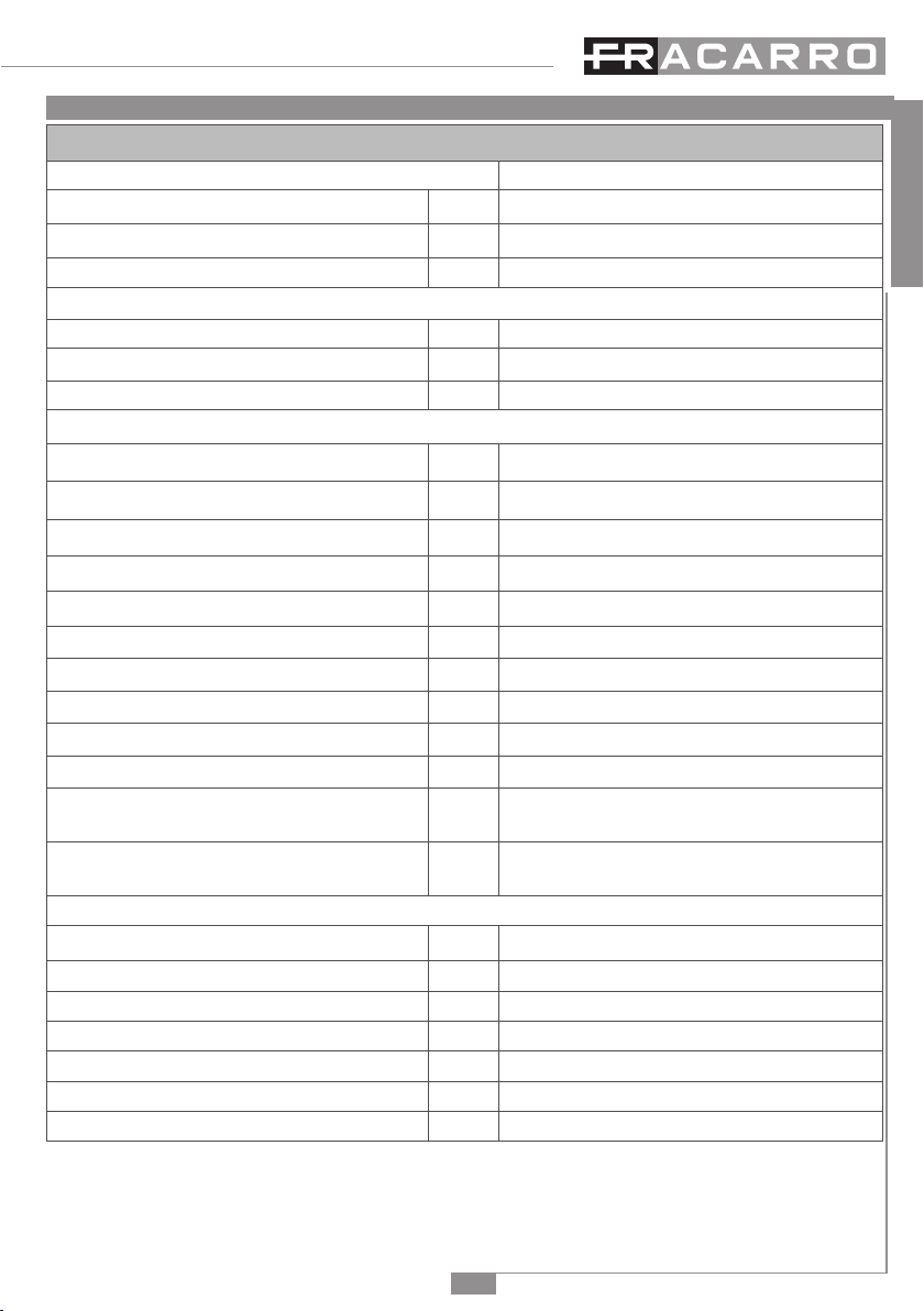
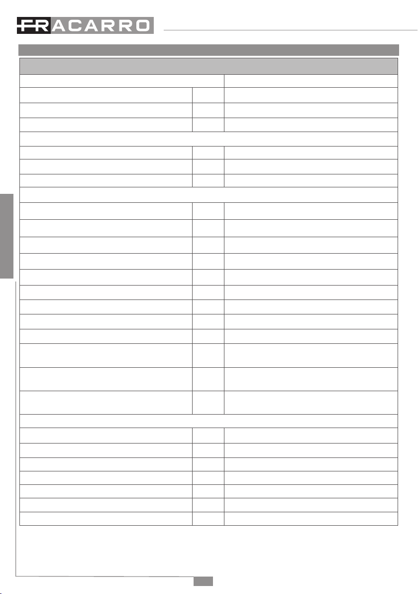
6. SPECIFICHE TECNICHE
OPT-RX SCD2
Codice Fracarro ( IT ) 270664
Ingresso Ottico n.° 1 FC/APC
Ingresso F Power n.° 1 alimentazione (12V/18V)
Uscite RF n.° 2 DCSS (TERR + SAT)
INGRESSO Ottico
Connettore Ottico FC/APC
Return loss ottico dB >45
Potenza ottica in ingresso (min ÷ max) dBm -14 ÷ -8
USCITE RF
Banda MHz 87 ÷ 790 / 950 ÷ 2150
Tipo di connettore F Femmina
Return loss dB 8
Livello d’uscita TV @ -14dBm ottici dBuV 91±5
MER uscita TV dB ≥23 (quando il MER in ingresso è maggiore o uguale a 30dB)
Controllo porte d’uscita DCSS
Uscita SAT per utenza a 25°C
dBuV
82
±2
MER uscita SAT
dB
≥10 (quando il MER in ingresso è maggiore di 15dB)
Banda uscita per Utenze SCR
MHz
1210, 1420, 1680 e 2040
Banda uscita per Utenze DCSS
MHz
985, 1050, 1115, 1275, 1340, 1485, 1550, 1615, 1745, 1810, 1875 e 1940
Banda uscita per Utenze DCSS (UK)
OPT-RX SCD2 UK (270663) MHz
980,1030,1080,1130,1280,1380,1480,1530,
1580,1630,1680,1730,1780,1830,1880,1930
Banda uscita per Utenze DCSS (ZA)
OPT-RX SCD2 ZA (270659) MHz
1210, 1420, 1680, 2040, 1006, 1057, 1108, 1159,
1261, 1312, 1363, 1471, 1522, 1573, 1624, 1731
Caratteristiche principali
Tensione di alimentazione V 12 - 18 V
Assorbimento A750mA (12 V) - 500mA (18V)
Temperatura di lavoro °C -10 ÷ +50
Protocolli STB compatibili prima e seconda generazione DiSEqC-SCIF (SCD/SCD2)
Segnalazioni luminose Led verde di alimentazione
Dimensioni mm 213x125x37
Peso g450