4
Italiano
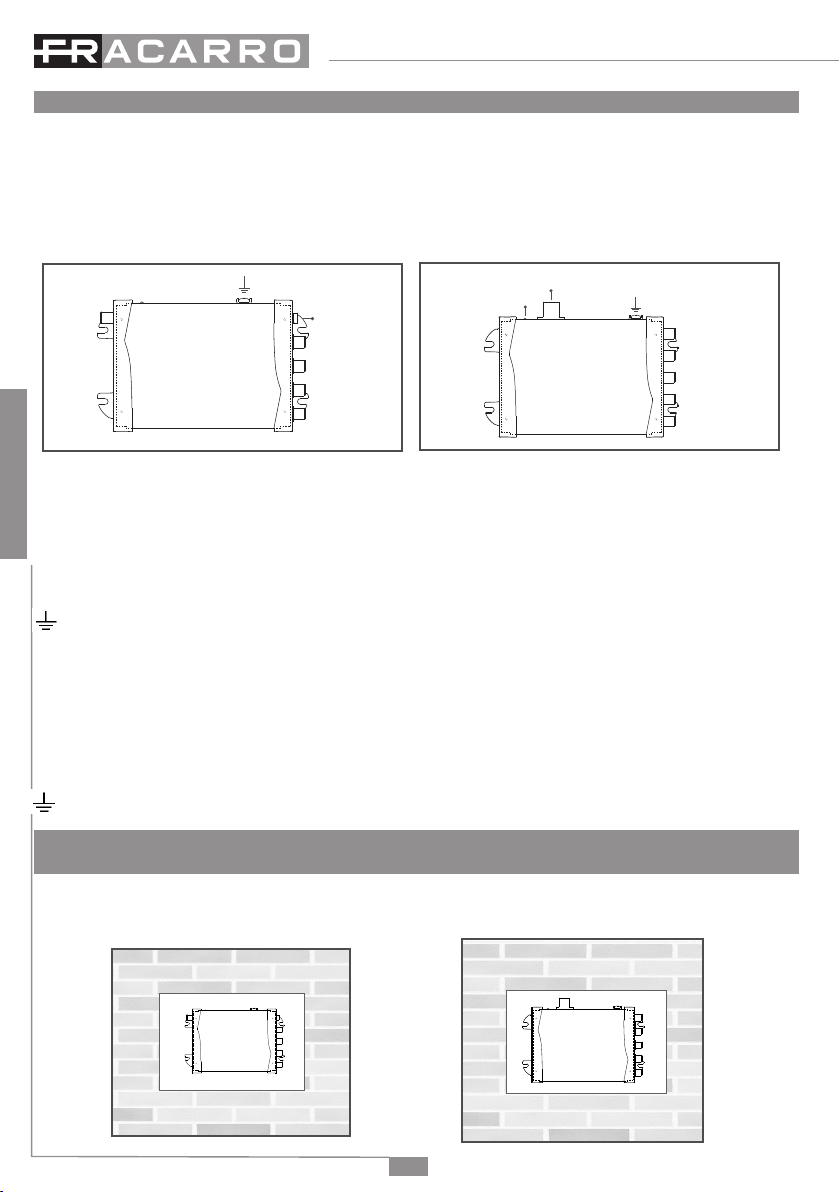
3.2 Alimentazione
OPT-RX QUAD MINI: Il ricevitore in bra può essere alimentato da STB (set-top box) oppure con l’uso di un alimentatore esterno
nel connettore d’ingresso DC IN optional.
OPT-RX 4 MINI: telealimentare il dispositivo attraverso le uscite SAT.
3.3Collegamentobraottica
ATTENZIONE: NonèpossibileeffettuareuncollegamentootticodirettotraOPT-TXDTeiricevitoriOPT-RXQUADMINIo
OPT-RX 4 MINI. Un link punto punto è possibile solo utilizzando appositi attenuatori ottici di linea in quanto la potenza massima
in ingresso dei ricevitori ottici OPT-RX QUAD MINI e OPT-RX 4 MINI non può superare -8dBm.
Vericareillivellootticodelsegnalesullabratramiteunmisuratoreotticoprimadicollegarlaalricevitore.
Utilizzare le bretelle SC-APC -> MINI (PR Adpt, cod. 287226) per collegare i dispositivi OPT alla distribuzione ottica (dispositivi
VOV e VOT).
Attenzione: Per preservare e proteggere le superci di contatto dei connettori ottici è buona regola mantenere le protezioni di
bussole e ferule in posizione no al momento della connessione o l’eventuale pulizia tramite appositi strumenti dedicati.
STRUZIONI PER L’UTILIZZO
4. ISTRUZIONI PER L’UTILIZZO
4.1Dimensionamentodiunimpiantoinbraottica
L’attenuazione ottica di tratta consentita al sistema deve essere compresa tra 15 e 21dB ottici. Fare riferimento alle caratteristiche
tecniche dei componenti passivi che compongono distribuzione per calcolare l’attenuazione di tratta.
Il ricevitore OPT-RX QUAD MINI garantisce un adeguato livello del segnale TV e SAT alla presa utente se il segnale ottico al suo
ingresso è compreso tra -8dBm e -14dBm ottici e il segnale RF in ingresso all’OPT-TX DT rispetta le indicazioni riportate nel
manuale del trasmettitore.
ATTENZIONE:
•NonsonoammessicollegamentidirettitraOPT-TXDTeOPT-RX,a meno dell’ utilizzo di opportuni attenuatori ottici di linea
• E’ indispensabile utilizzare un misuratore di segnale ottico per vericare il livello ottico d’ingresso al ricevitore ed evitare di
danneggiare il fotodiodo ricevente (potrebbe danneggiarsi se il segnale in ingresso è superiore a 0dBm).
4.2Livelliinuscitaalricevitoreottico
Il livello in uscita dai ricevitori ottici OPT-RX dipende dal numero di segnali trasmessi in bra e dell’attenuazione ottica della tratta.
Si tenga conto che 1dB di perdita ottica equivale a 2dB di attenuazione al livello elettrico (RF).
OPT-RX QUAD MINI
Di seguito vengono riportati alcuni livelli di riferimento dei segnali in uscita al ricevitore OPT-RX QUAD MINI:
TV (DVB-T/CATV)
La potenza totale in uscita è pari a -32dBm (77dBuV) con 21dB di attenuazione ottica, per cui meno multiplex vengono trasmessi,
maggiore sarà il livello e la qualità in uscita
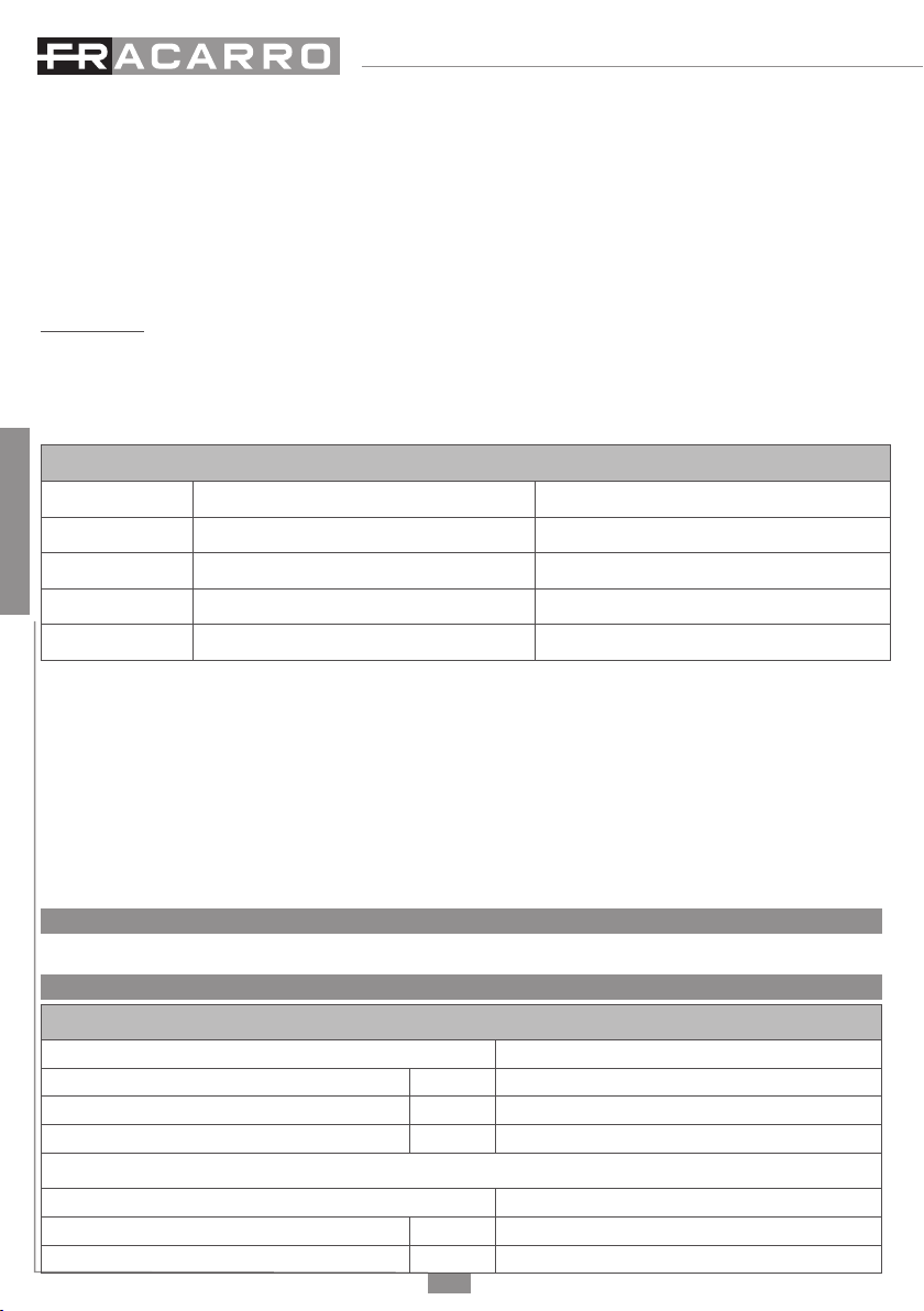
LivelloRFinuscitaperMUX
NumeroMUX Livellootticoalricevitore-8dBm Livellootticoalricevitore-14dBm
40 81 dBµV 69 dBµV
16 84 dBµV 72 dBµV
8 87 dBµV 75 dBµV
4 90 dBµV 78 dBµV
Tab.1 indicazioni livelli di uscita all’OPT-RX QUAD MINI - segnale TV
Nota: 1dB ottico equivale a 2dB a livello elettrico (RF).
SAT
Il livello tipico del segnale SAT (40 Trasponder distribuiti) in uscita dell’OPT-RX QUAD MINI è:
• 64dBuV per transponder con un livello ottico di -14dBm in ingresso al ricevitore (21dB di attenuazione ottica)
• 76dBuV per transponder con un livello ottico di -8dBm in ingresso al ricevitore (15dB di attenuazione ottica)