10
ITALIANO
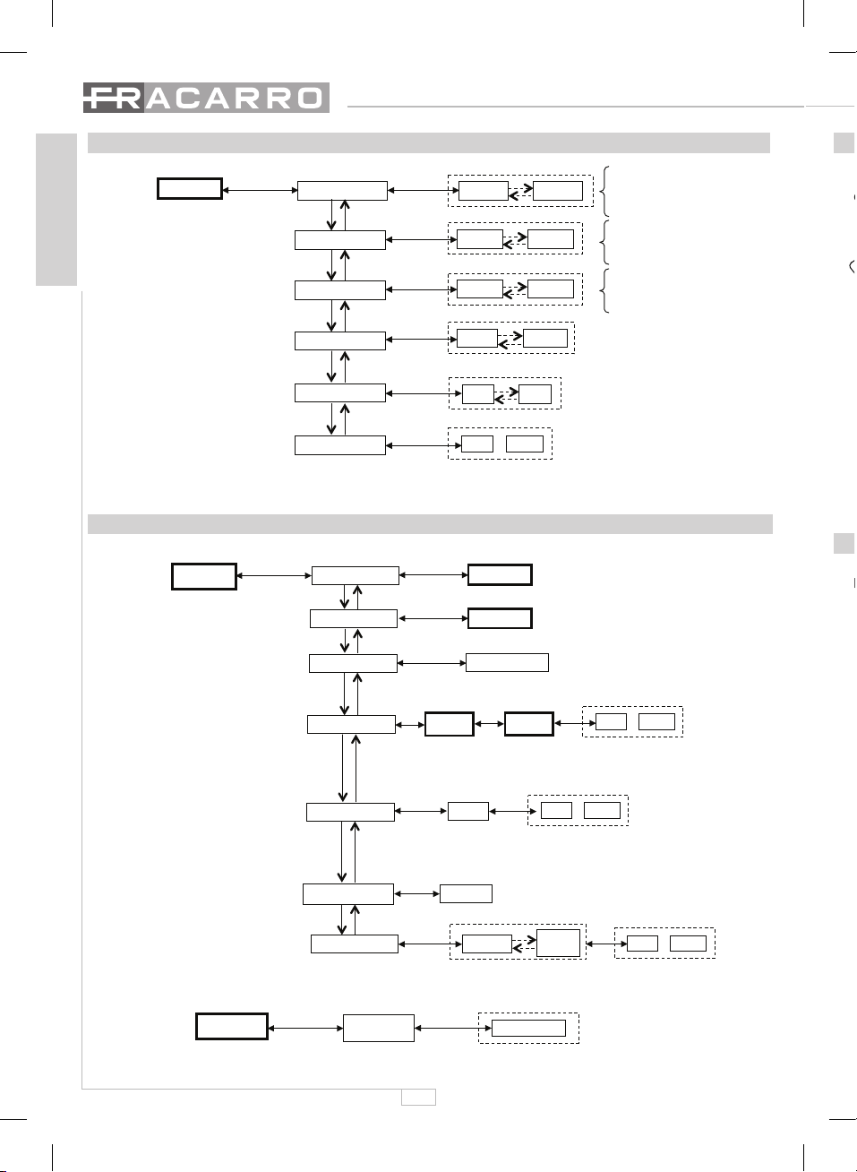
Il menù di programmazione OSD sarà opportunamente commentato in ogni sua voce (HELP) in modo da
agevolare le operazioni di settaggio dei vari parametri.
Al termine dell’operazione il menù OSD si dissolverà dopo circa 2 minuti di inattività da parte dell’operatore o
all’uscita del menù navigazione OSD.
8. SPECIFICHE TECNICHE
KDSR MONO KDSR MULTISTD KDSR-S KDSR-AV
Frequenza di ingresso 950 ÷ 2150MHz
Livello di ingresso 43 ÷ 84dBµV
Input return loss > 9 dB
Passo di sintonia 1 MHz
AFC ±3 MHz (a 27,5Msym/s, -60dBm, C/N=10dB)
Guadagno di passaggio ingresso
autodemiscelante 0 ÷ -4dB
Numero max. di moduli da demi-
scelare in ingresso Dipende da frequenza e livello del segnale in input
Telealimentazione LNB 0/14/18V, 0/22KHz, 200mA 14V - 100mA 18V
DiSEqC 1.0
Symbol rate 2 ÷ 45 Msym/s
FEC Auto (1/2, 2/3, 3/4, 5/6, 7/8)
MPEG2 Main level@Main profile
Bit rate video 1,5 .. 15Mbit/s
Formato video letter box, pan_scan, combined, adapted 16/9
Bit rate audio Fino a 348 Kbits/s
Formato audio Mono, Mono lingua1, Mono lingua2 Mono, Stereo, Dual
Sound, Auto
Mono, Mono
lingua1, Mono
lingua2, Stereo
Uscita RF 47 ÷ 862MHz
Programmazione canale uscita A frequenza (step 250KHz) o a canale
Canalizzazioni disponibili per la
programmazione Europa Europa, Francia,
UK, Australia Europa
Tipo modulatore VSB mono
PAL B/G VSB mono
multistandard VSB stereo
PAL B/G
Livello di uscita 90 dBµV
Regolazione livello uscita 0÷15dB tramite programmatore TPE
Segnale test Schermo nero o righe bianche Schermo nero
Uscita video 1Vpp - 75ohm su connettore RCA
Uscita audio 0,5Vrms - 10Kohm su connettori RCA
Uscite RF 2 uscite automiscelanti su connettori F
Perdite di automiscelazione < 1,5 dB@ 860MHz
Standard PAL-BG
PAL-M, PAL-I, PAL-
DK, PAL-N, PAL-H,
SECAM-L, NTSC-M
PAL-BG
PAL, PAL-N, SECAM-
L, NTSC-M,
PAL-M
Temperatura di funzionamento -10 ÷ +45°C
Alimentazione 12VDC
Potenza assorbita 12,1W 12,7W 8W
Corrente assorbita @ 12V 1010mA 1060mA 670mA
I dati tecnici sono nominali e riferiti alla temperatura ambiente di 25°C.
1. SAFETY WARNINGS
The product must be installed only by qualified persons, according to the local safety standards and regulations.
Installation warnings
•
The product must be installed indoors, in a dry place.
•
Humidity and condensation could damage the product. In case of condensation, wait until the product is dry
before using it.
•
Don’t install the product above or close to heat sources, in dusty places or where it might come into contact
with corrosive substances.
•
Leave enough space around the product housing to ensure sufficient ventilation. An excessive operating
temperature and/or excessive heating may affect the performance and the life of the product.
In accordance with the European Directive 2004/108/EC (EMC), the product shall be installed using devices,
cables and connectors that allow to comply with this directive requirements for fixed installations.
Earthing the antenna system:
the DIN bar, where the unit will be installed, must be connected to the earth electrode of the antenna system, in
accordance with standard EN60728-11. It is recommended to follow the provisions of EN60728-11 and not to
connect the DIN bar to the protective earth (PE) of the supply mains.
IMPORTANT: only instructed and authorized persons can open the product. In case of failure, do not try to repair
the product; otherwise the guarantee will no longer be valid.
2. PRODUCT DESCRIPTION
The KDSR is a digital receiver for the distribution of satellite digital programs transmitted free-to-air with
QPSK modulation. It receives an QPSK digital transponder from which it extracts audio and video signals
transmitted from a transmitted free-to-air program. These signals generate a channel that will later be distrib-
uted, using a standard TV distribution network. The version of the unit with A/V outlets can be connected to
external modulators.
The modules are installed on a standard DIN bar and are supplied by the KP feeders of the K series. They are
programmed by a TPE programmer. See fig. 1 to spot the SAT signal input (from the dish), the demixed out-
put of the SAT signal to other modules, the RCA outputs with the A/V signals, the input of the self-mixing line
and the output of the generated signal. The KDSR-AV version doesn’t have a RF output - only RCA outputs.
ASSEMBLING ON DIN BAR
KDSR
KDSR-S
KDSR-AV
KDSR-M
KD100
1
2
3
POSITION OF
SPACERS
CLIP HOOK TO THE
DIN BAR
SAT INPUT
SAT OUTPUT
AUDIO R OUTPUT
AUDIO L OUTPUT
VIDEO OUTPUT
12V
MIX INPUT
(only for KDSR, KDSR-S and KDSR-M)
OUTPUT
(only for KDSR, KDSR-S and KDSR-M)
LED
RJ45 OUTLET
FOR TPE
Fig.1 Fig.2
See the last pages of these instructions for the complete list of characteristics.
The maximum number of connecting modules in input demixing depends on the level, the quality and
frequency of the SAT signal that you want to receive. Typically, for a good quality signal, the signal should
demix among 5 or 6 modules. KRF15 flexible bridges can be used as well as KPR52 rigid bridges. To make the
rigid bridges installation easier, to ensure the proper ventilation of the modules and to simplify the installation
operations, we recommend using the supplied black plastic spacers. They must be connected to the clip hook