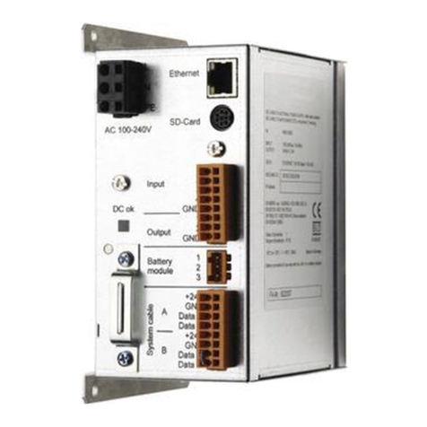
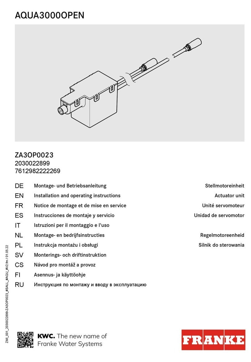
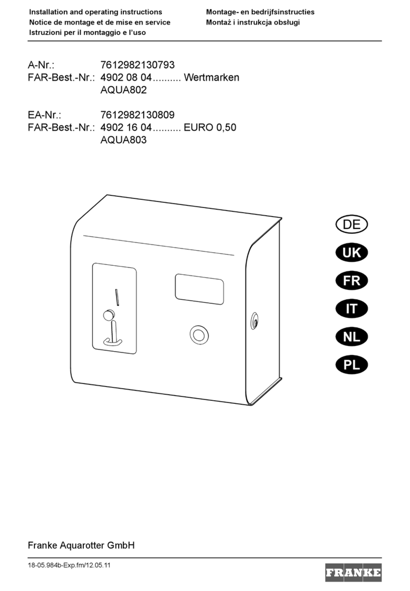
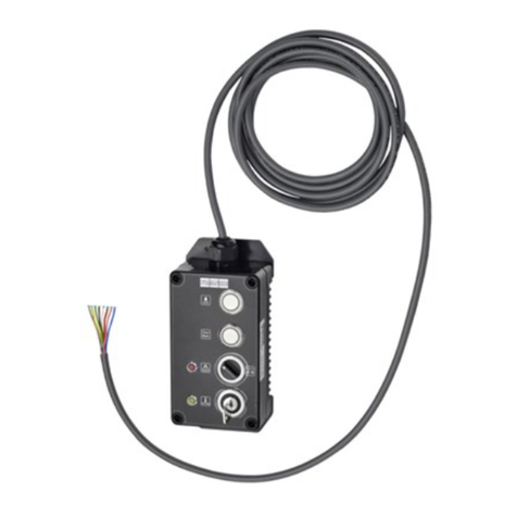
Franke ECC2 Function Controller User manual

ZMI_001_2000108123-ZA3OP0011_#SALL_#AQU_#V3.fm / 10.10.17
Installation and operating instructions Instrucciones de montaje y uso
Notice de montage et de mise en service Istruzioni per il montaggio e l’uso
EA-Nr.: 7612982185335
FAR-Best.-Nr.: 2000108123
ZA3OP0011
EA-Nr.: 7612982213687
FAR-Best.-Nr.: 2030016282
ZA3OP0022
DE
EN
FR
ES
IT

2
Inhaltsverzeichnis35-31.fm
...................................................................................3
Please refer to the graphics in the German Installation and
Operating Instructions.
...................................................................................20
Les graphiques sont disponibles dans la notice de montage et
de mise en service allemande.
...................................................................................38
Por favor, consulte los gráficos en las instrucciones alemanas
de montaje y uso.
...................................................................................56
Per le grafiche fare riferimento alle Istruzioni per il montaggio
e l’uso in tedesco.
EN
FR
ES
IT

- 3 -
ZMI_001_2000108123-ZA3OP0011_#SEN_#AQU_#V3.fm
0English
ECC2 Function Controller - A3000 open with
Ethernet Connection, 230 V AC / 24 V DC
2000108123
2030016282 .......................... including BMS data protocols
Please refer to the graphics in the German Installation and Operating Instructions.
Contents
1. Abbreviations and Units . . . . . . . . . . . . . . . . . . . . . . . . . . . . . . . . 4
2. Key . . . . . . . . . . . . . . . . . . . . . . . . . . . . . . . . . . . . . . . . . . . . . . . . 4
3. Warranty . . . . . . . . . . . . . . . . . . . . . . . . . . . . . . . . . . . . . . . . . . . . 4
4. Important Notes . . . . . . . . . . . . . . . . . . . . . . . . . . . . . . . . . . . . . . 4
Description of Product
5. Application . . . . . . . . . . . . . . . . . . . . . . . . . . . . . . . . . . . . . . . . . . 5
6. Technical Specifications . . . . . . . . . . . . . . . . . . . . . . . . . . . . . . . . 6
7. Special Features. . . . . . . . . . . . . . . . . . . . . . . . . . . . . . . . . . . . . . 7
8. Dimensions. . . . . . . . . . . . . . . . . . . . . . . . . . . . . . . . . . . . . . . . . . 7
9. Connections . . . . . . . . . . . . . . . . . . . . . . . . . . . . . . . . . . . . . . . . . 7
10. Pin Configurations . . . . . . . . . . . . . . . . . . . . . . . . . . . . . . . . . . . . 8
Installation, Function and Commissioning
11. Assembly Instructions. . . . . . . . . . . . . . . . . . . . . . . . . . . . . . . . . . 10
12. Display with Menu Keys . . . . . . . . . . . . . . . . . . . . . . . . . . . . . . . . 11
13. Permissions / Passwords . . . . . . . . . . . . . . . . . . . . . . . . . . . . . . . 12
14. Display for Staff Level. . . . . . . . . . . . . . . . . . . . . . . . . . . . . . . . . . 13
15. Settings in Technician Level . . . . . . . . . . . . . . . . . . . . . . . . . . . . . 14
16. Start Web Application . . . . . . . . . . . . . . . . . . . . . . . . . . . . . . . . . . 16
17. Connection Example . . . . . . . . . . . . . . . . . . . . . . . . . . . . . . . . . . 17
18. UPS . . . . . . . . . . . . . . . . . . . . . . . . . . . . . . . . . . . . . . . . . . . . . . . 17
Maintenance
19. Fault Correction . . . . . . . . . . . . . . . . . . . . . . . . . . . . . . . . . . . . . . 17
20. Accessories . . . . . . . . . . . . . . . . . . . . . . . . . . . . . . . . . . . . . . . . . 17
21. Error Code . . . . . . . . . . . . . . . . . . . . . . . . . . . . . . . . . . . . . . . . . . 18
EN

ZMI_001_2000108123-ZA3OP0011_#SEN_#AQU_#V3.fm
- 4 -
1. Abbreviations and Units
2. Key
Warning!
Failure to observe can result in injury or even death.
Caution!
Failure to observe can result in material damage.
☞Important!
Failure to observe can cause the product to malfunction.
☞Useful information for optimally handling the product.
3. Warranty
Liability is accepted according to the General Terms and Conditions of Business and
Supply.
Use original replacement parts only!
4. Important Notes
• Installation, commissioning and maintenance are to be performed only by a
qualified technician according to the instructions provided and in accordance with
legal requirements and acknowledged rules of technology.
• All technical connection regulations specified by the local water and electricity
supply utility companies must be complied with.
• All work must be carried out in a de-energised state.
EMC Electromagnetic compatibility
RCD Residual Current Protective Device,
Earth leakage circuit breaker
SELV Safety Extra Low Voltage
UPS Uninterruptible power supply
EA No. European Article Number
FAR Order No. Franke Aquarotter Order Number
Conversion 1 mm = 0.03937 inches
1 inch = 25.4 mm
All length specifications in the graphics are in mm.

- 5 -
ZMI_001_2000108123-ZA3OP0011_#SEN_#AQU_#V3.fm
• Because of the IP20 protective system used, the device must be operated in dry
rooms only.
• Only appliances with protection class III (SELV) may be connected to the unit.
• During the warranty period, the factory-set output voltage 24V may only be
changed by the Franke-Aquarotter customer service department.
• Secure the electric connection with an earth leakage circuit breaker (RCD).
• Proper cooling must be assured. To ensure an unimpeded flow of cooling air, it is
important to maintain a minimum distance of 15 mm to adjacent equipment.
• All rights reserved to make technical alterations.
5. Application
ECC2 Function Controller - A3000 open with Ethernet and CAN bus connection. For
connecting AQUA 3000 open fittings/electronic system modules for the purpose of
supplying power and external control, such as settings for fittings and communi-
cation. For mounting on a 35 mm DIN rail in the on-site switch-gear cabinet
(provided by customer), for wall mounting or in an electrical distribution system in
accordance with the applicable VDE regulations.
Functions of integrated digital inputs with LED status display:
– Control for thermal disinfection
– Acknowledgment of collective fault signals
– Switching program modes (e.g. night mode or holiday mode)
Functions of the integrated potential-free digital outputs with LED status display:
– Control for thermal disinfection
– Display of collective fault signals
Storage of statistical data with date and time, can be read via the USB interface in
csv format.
Additional functions can be set via a web browser:
– Switch-off for cleaning
– Triggering hygiene flushing
– Simultaneity suppression
– Sequential controls
– System flushing
– Reduction in flow duration

ZMI_001_2000108123-ZA3OP0011_#SEN_#AQU_#V3.fm
- 6 -
6. Technical Specifications
Product group: Primary switched-mode voltage regulator (single
phase, primary switched built-in power supply with
Ethernet-CAN coupler)
EMC: EN 61000-6-3 (electromagnetic emission)
EN 61000-6-2 (electromagnetic immunity)
Electrical safety: EN 60950
Protective system IP 20
Protection class: I
Test voltage: 4.2 kV DC
Dimensions (W x H x D): 144 × 144 × 151 mm
Ambient temperature: -10°C to 60°C / 70°C for 10 min
Cooling: Natural convection
Humidity: 100% relative humidity
There must be no dew formation when the system is
to be commissioned.
Storage temp.: -40°C to 80°C
Long-term storage: To maintain the condensers, apply mains voltage to
the device for at least 5 min. every two years.
Input
Input AC: Rated voltage 100 – 240 V AC / 50 – 60 Hz
Rated current: 0.6 A at 230 V AC
Overvoltage protection: Varistor in the input circuit
Connections: 3 x 1.5 mm²
Output
Output DC (SELV): Rated voltage 24 V DC
Range 22 – 28 V (preset to 24 V)
Rated current: 2.5 A at 24 V DC
Ripple: 150 mVpp (at 20 MHz)
Efficiency: 89 %
Current limitation: from 1.1 × IRated
Connections: WAGO 734 Series multi-connector system for max.
1.5 mm²
Digital connections
Connection facilities: Ethernet, USB 2.0, UPS
Connections: WAGO 734 Series multi-connector system for max.
1.5 mm²

- 7 -
ZMI_001_2000108123-ZA3OP0011_#SEN_#AQU_#V3.fm
7. Special Features
• Wide range input for AC
• Maintenance free
• Open-circuit proof
• Short-circuit proof
• Protected both on the inside as well as the outside by an internal fuse
• Protected on the outside by an electronic voltage/current controller
• Output voltage adjustable
• in parallel with factory-set default output voltage of 24 V
☞During the warranty period, the factory-set output voltage 24 V may only be altered
by the customer service department.
• Monitoring by means of an integrated Ethernet-CAN module
• Facility for connecting a UPS
• USB port for offline data transfer to a PC, RJ45 connector for 10/100 Mbit
Standard Ethernet for PC or building network
• Interfaces for optional expansion module (I/O) and wireless module (GSM)
• BMS (building management system) connection possible using protocols BacNet
- IP, KNX - IP and Modbus - TCP
• Visualization and parametrization of the fittings network via integrated display or
web browser
8. Dimensions
9. Connections
1 Port for USB stick (for updates and storing statistical data)
2 RJ45 interface for data communication
(LAN and BMS)
3 Service interface RS232
4 Connection for system lines (operating voltage and CAN bus system; max. 32 fittings)
5 Connector for UPS power supply (optional)
6 Connector for wireless module (optional)
7 Connector for expansion module (optional)
8 Power supply connection
9 Connections for inputs and outputs (supplementary functions)
10 Display with menu buttons (siehe Kapitel 12.)

ZMI_001_2000108123-ZA3OP0011_#SEN_#AQU_#V3.fm
- 8 -
Inputs
Input 1 ... Thermal disinfection
Input 2 ... Abort thermal disinfection
Input 3 ... Acknowledge outputs
Input 4 ... Switching program modes
Outputs
Output 1 ... Thermal disinfection active
Output 2 ... Thermal disinfection
Abort (manual)
Output 3 ... Thermal disinfection
Safety abort
Output 4 ... Collective fault message
RD ... red
BU ... blue
WH ... white
BK ... black
10. Pin Configurations
SELV power supply and data bus (cable system)
Pin Signal Level Color Function
1 Data-L ±0.2 V DC to
±5 V DC
BK
Data bus for bus isle
2 Data-H ±0.2 V DC to
±5 V DC
WH
3 GND 0 V DC BU Reference for bus isle
looped through
4 24 V 24 V DC RD Supply voltage for bus
isle looped through
5 Data-L ±0.2 V DC to
±5 V DC
BK
Data bus for bus isle
6 Data-H ±0.2 V DC to
±5 V DC
WH
7 GND 0 V DC BU Reference for bus isle
looped through
8 24 V 24 V DC RD Supply voltage for bus
isle looped through

- 9 -
ZMI_001_2000108123-ZA3OP0011_#SEN_#AQU_#V3.fm
UPS (battery module)
Factory settings:
Digital inputs IN1 through IN4 (Input) and
digital outputs OUT1 through OUT2 (Output)
Input 1 - Function:
Start command for thermal disinfection
☞The contact must be closed at least 5s and no more than 2 minutes
Input 2 - Function:
Abort thermal disinfection
☞This is triggered with a pulse.
• Thermal disinfection is stopped.
• A safety window of at least 30s passes before the fittings are flushed, and the
system then returns to its normal mode of operation. This process is then
recorded as being "not successful".
• The fittings start the cooling phase.
Input 3 - Function:
Acknowledgment for outputs
☞This is triggered with a pulse.
• All digital outputs are reset.
Input 4 - Function:
Switching program modes
example for: summer/winter mode, day/night mode or room occupied/not occupied.
☞The input can be connected with a switch, time switch or GLT contact.
• Functionality depends on the contents of the program ID within the electronic
module.
Pin Signal Level Current Function
1 UPS LOW UPS plugged on
HIGH no UPS plugged on
2 GND Reference
3 24 V 24 V DC 2.5 A Supply voltage for bus isle
looped through

ZMI_001_2000108123-ZA3OP0011_#SEN_#AQU_#V3.fm
- 10 -
Output 1 - Function:
Relay contact 48 VDC/1 A and 240 V AC/2 A
Assigned to thermal disinfection.
☞Normal functionality: Permanently "ON" for the duration of the thermal disin-
fection process
• Acknowledgement see IN3
Output 2 - Function:
Relay contact 48 VDC/1 A and 240 V AC/2 A
Assigned to thermal disinfection.
☞Normal functionality: Permanently "ON" when thermal disinfection was aborted
manually.
• Acknowledgement see IN3
Output 3 - Function:
Relay contact 48 VDC/1 A and 240 V AC/2 A
Assigned to thermal disinfection.
☞Normal functionality: Permanently "ON" when thermal disinfection was aborted
by the system.
• Acknowledgement see IN3
Output 4 - Function:
Relay contact 48 V DC/1 A and 240 V AC/2 A
Assigned to collective fault messaging.
☞Normal functionality: Permanently "ON" when a fault message is being waved.
• Acknowledgement see IN3
11. Assembly Instructions
☞When installing several devices, it is essential to ensure an unimpeded flow of
cooling air by maintaining a minimum distance of 15 mm to adjacent parts.
☞Mount the ECC2 function controller (1) on a rail.
11.1
Snap-lock the lower edge (3) into the rail.
11.2
Push up the ECC2 function controller.
11.3
Snap-lock the upper edge (2) into the rail.
11.4
Connect the system cable (4).
Connecting input and output cables (5)
☞The maximum cross section of an input/output cable is 1.5 mm².
11.5
Strip off 8 mm of the ends of the input/output cables.
☞Apply wire-end ferrules to flexible electric cables.
11.6
Connect the input/output cables according to the pin configuration (siehe Kapitel 9.).

- 11 -
ZMI_001_2000108123-ZA3OP0011_#SEN_#AQU_#V3.fm
11.7
Connect the desired optional equipment.
11.8
Connect the power cord.
• After the operating voltage has been switched on, the display shows the startup
screen
12. Display with Menu Keys
Escape - Aborts each control process and/
or returns to the previous menu level
Cursor up - Navigates upwards line by line
in the menu
Cursor down - Navigates downwards line
by line in the menu
Cursor right - Navigates to the right in the
menu
Cursor left - Navigates to the left in the
menu
Enter - Accepts a value and/or continues
one menu level further

ZMI_001_2000108123-ZA3OP0011_#SEN_#AQU_#V3.fm
- 12 -
13. Permissions / Passwords
Permission Level
Different permission levels are available for viewing and changing operating
parameters within the multi-function power supply control:
Entering passwords (PIN)
Resetting a Permission Level
The permission level must be reset when, for example, the control system must be
immediately protected against unauthorized use after service work was done in the
Technician Level.
☞If no entries are made in the control panel for more than 4 min., the permission level
is automatically reset.
Staff Level No password needed, just for viewing some
parameters
Technician Level Customer/Operator password - Changing all
permissions, saving, etc.
The password consist of a 5-digit numerical code.
13.1
Press key .
13.2
Use keys and to enter the
required digit.
13.3
Use key to jump to the next
location.
☞When the PIN has been entered successfully the display will show the main menu.
When a wrong number is confirmed with the enter key, the display will remain in
the 'Enter PIN:' status.
PIN
0 0 0 0 0

- 13 -
ZMI_001_2000108123-ZA3OP0011_#SEN_#AQU_#V3.fm
14. Display for Staff Level
After the operating voltage has been
switched on, the display shows the startup
screen.
14.1
Use keys and to set the
required page.
Page 1
Shows how many fittings are
connected and in operation.
e.g.: 8 of 10 connected fittings are in
operation
Page 2
Displays the operating voltage for the
valves.
Page 3
Displays
– how many error messages are
stored.
– The last 5 error messages with
date, time and error code
(siehe Kapitel 21.).
Page 4
Shows which version of the system
software is installed on the ECC2
function controller.
Page 5
Shows which device IDs and network
IDs the ECC2 function controller has.
ECC2 ECC-Name
22/01/2013
14:21
Menu
Page 1
Modules
Fittings
8/10
Page 2 Voltage
24.63V
Page 3 Fault (9)
22.01.2013 13:43 1000
22.01.2013 13:39 1
22.01.2013 13:36 1
21.01.2013 07:50 1
18.01.2013 08:52 1
Page 4 Version
Version x.xx
Page 5 Static IP
IP 10.222.48.226
NM 255.255.0.0
GW 10.222.0.50
DNS
MAC 00-04-A3-87-3D-B5

ZMI_001_2000108123-ZA3OP0011_#SEN_#AQU_#V3.fm
- 14 -
15. Settings in Technician Level
15.1
Enter the PIN (siehe Kapitel 13.).
• The main menu appears.
15.2
Use keys and to select the
desired menu.
15.3
Confirm with key .
• The desired menu opens up.
Network configuration
15.4
Select the "Network Config." menu.
15.5
Use keys and to select the
desired number.
15.6
Use keys and to select the
desired number block.
15.7
Use keys and to enter the
desired number.
15.8
Confirm with key .
• The entries are saved.
• The main menu opens.
or
Press key .
• The entries are not saved.
• The main menu opens.
Select language
15.9
Press and hold key approx. 3
seconds.
15.10
Use keys and to enter the
desired language.
15.11
Confirm with key .
Main menu
Network config.
Date/time format
Set date/time
Temperature
Restart
OKCancel
Network configuration
IP 010.222.048.222
NM 255.000.000.000
GW 010.222.000.050
DNS 255.000.000.000
OKAbort
select language
Deutsch
Englisch
čeština
Dansk OKCANCEL

- 15 -
ZMI_001_2000108123-ZA3OP0011_#SEN_#AQU_#V3.fm
Date/time formats
15.12
Select the "Date/Time" format menu.
15.13
Use keys and to select the
desired format.
15.14
Press key .
15.15
Use keys and to set the
desired format.
15.16
Confirm with key .
• The entries are saved.
• The main menu opens.
or
Press key .
• The entries are not saved.
• The main menu opens.
Set Date/Time
15.17
Select the "Set Date/Time" menu.
15.18
Use keys and to select
between date and time.
15.19
Press key .
15.20
Use keys and to set the
desired date and time.
15.21
Confirm with key .
• The entries are saved.
• The main menu opens.
or
Press key .
• The entries are not saved.
• The main menu opens.
Date/time formats
Date DD.MM.YYYY
24H format
Summer time
OKCancel
Set Date/Time
Date 21.01.2013
Time 15:2
1
OKAbort

ZMI_001_2000108123-ZA3OP0011_#SEN_#AQU_#V3.fm
- 16 -
16. Start Web Application
16.1
Start a PC in the network.
16.2
Select an Internet browser.
16.3
Enter the IP of the ECC2 function controller in the address bar of the Internet
browser.
16.4
Enter the User and Password.
16.5
Click the "Login" button.
☞A guide for the Web application is provided in the "Help" menu.
Temperature/Unit (for electronic group
thermostat)
15.22
Select the "Temperature" menu.
15.23
Use keys and to select the
units or the desired mixer.
15.24
Press key .
15.25
Use keys and to set the
desired unit or the desired tempe-
rature.
15.26
Confirm with key .
• The entries are saved.
• The main menu opens.
or
Press key .
• The entries are not saved.
• The main menu opens.
Restart ECC2 function controller
15.27
Select the "Restart" menu.
• The ECC2 function controller is
restarted.
Temperature/Unit
°C/°F °C
Mixer 1 65.0°C
Mixer 2 65.0°C
Mixer 3 65.0°C
OKAbort

- 17 -
ZMI_001_2000108123-ZA3OP0011_#SEN_#AQU_#V3.fm
17. Connection Example
A: max. 200 m system cable or max. 32 fittings with a total performance of max. 60 W
B: Ethernet
C: Terminating resistor
D: Mains 250 V AC
Lead power cord via main switch or fuse
RD ... red
BU ... blue
WH ... white
BK ... black
18. UPS
The ECC function controller automatically detects the presence of any connected
UPS. The UPS is then checked every 25 hours. The ECC checks the function of the
UPS by switching off its own supply voltage for 5 seconds. The system then
operates with power from the UPS. During this time the ECC function controller
measures the voltage. If the voltage is less than 22 V, a corresponding message is
displayed.
19. Fault Correction
If you are unable to correct a fault or if the fault is not described in the fault correction
section, please inform our customer service department!
20. Accessories
Fault Cause Remedy
No output voltage is
present, the display
does not light
– Voltage supply interrupted ➯Restore it
– ECC2 function controller defective ➯Replace it
Accessories Order No.
Wireless module . . . . . . . . . . . . . . . . 2000108125
Rod antenna . . . . . . . . . . . . . . . . . . . 2000110895
Wall antenna . . . . . . . . . . . . . . . . . . . 2000110896
Active antenna . . . . . . . . . . . . . . . . . 2000110897
Expansion module . . . . . . . . . . . . . . 2000108124
UPS power supply . . . . . . . . . . . . . . 2000100977

ZMI_001_2000108123-ZA3OP0011_#SEN_#AQU_#V3.fm
- 18 -
21. Error Code
Code Meaning
1 System was started
2 System is being shut down.
3StartTD
4 TD completed successfully
5 TD was terminated after an error
100 Start TD Phase 1
110 TD Phase 1 not confirmed by all modules
200 Start TD Phase 2
210 TD Phase 2 not confirmed by all tank modules
211 TD Phase 2 aborted after timeout
300 Start TD Phase 3
310 Rapid heating not confirmed by all EMs
311 TD Phase 3 aborted after timeout
312 TD Phase 3 not confirmed by all masters
313 Rapid heating could not be stopped
400 Start TD Phase 4
410 TD Phase 4 not confirmed by all master modules
411 Master reports safety switch-off
450 Master reports completion (log with temperature)
451 EM reports quick heating terminated
500 Start TD Phase 5 (however only group starts are logged)
501 TD Phase 5 Group 1 started
502 TD Phase 5 Group 2 started
503 TD Phase 5 Group 3 started
504 TD Phase 5 Group 4 started
505 TD Phase 5 Group 5 started
506 TD Phase 5 Group 6 started
507 TD Phase 5 Group 7 started
508 TD Phase 5 Group 8 started
509 TD Phase 5 Reheating time
510 TD Phase 5 not confirmed by all EMs of the group
511 TD Phase 5 aborted after timeout in the group
512 TD Phase 5 tank stop not confirmed
550 TD Phase 5 tank stop started
600 Start TD Phase 6
601 TD Phase 6 Group 1 started
Code Meaning

- 19 -
ZMI_001_2000108123-ZA3OP0011_#SEN_#AQU_#V3.fm
602 TD Phase 6 Group 2 started
603 TD Phase 6 Group 3 started
604 TD Phase 6 Group 4 started
605 TD Phase 6 Group 5 started
606 TD Phase 6 Group 6 started
607 TD Phase 6 Group 7 started
608 TD Phase 6 Group 8 started
610 Master has not confirmed Phase 6
611 EMs in current group have not been confirmed Phase 6
620 TD Phase 6 started because of abort
650 TD Phase 6 Cooling of the TD master modules confirmed
651 TD Phase 6 Cooling terminated after safety window
700 TD Phase 7 started (return to normal operation)
710 TD Phase 7 Normal operation not confirmed by all modules
1000 CAN bus error
1001 CAN bus OK
1002 Leakage detected
2036 CAN bus error
2037 Opto-sensor missing
2041 Solenoid valve 1 cable broken
2042 Solenoid valve 1 short circuit
2044 Solenoid valve 2 cable broken
2045 Solenoid valve 2 short circuit
2047 Undervoltage
2061 Temperature sensor 1 cable broken
2062 Temperature sensor 2 cable broken
2068 Opto-sensor missing
2069 Temperature sensor 1 short circuit
2070 Temperature sensor 2 short circuit
2073 Opto-sensor missing
4000 EM not sending data
4001 EM has commenced sending data again

ZMI_001_2000108123-ZA3OP0011_#SFR_#AQU_#V3.fm
- 20 -
0Français
Contrôleur de fonctions ECC2 - A3000 ouvert avec
connexion Ethernet, 230 V CA / 24 V CC
2000108123
2030016282 .......................... Protocoles de données inclus
Les graphiques sont disponibles dans la notice de montage et de mise en service
allemande.
Sommaire
1. Abréviations et unités . . . . . . . . . . . . . . . . . . . . . . . . . . . . . . . . . . 21
2. Explication des symboles . . . . . . . . . . . . . . . . . . . . . . . . . . . . . . . 21
3. Garantie . . . . . . . . . . . . . . . . . . . . . . . . . . . . . . . . . . . . . . . . . . . . 21
4. Remarques importantes . . . . . . . . . . . . . . . . . . . . . . . . . . . . . . . . 22
Description du produit
5. Application . . . . . . . . . . . . . . . . . . . . . . . . . . . . . . . . . . . . . . . . . . 22
6. Données techniques. . . . . . . . . . . . . . . . . . . . . . . . . . . . . . . . . . . 23
7. Caractéristiques principales . . . . . . . . . . . . . . . . . . . . . . . . . . . . . 24
8. Dimensions. . . . . . . . . . . . . . . . . . . . . . . . . . . . . . . . . . . . . . . . . . 25
9. Raccordements . . . . . . . . . . . . . . . . . . . . . . . . . . . . . . . . . . . . . . 25
10. Affectation des raccords . . . . . . . . . . . . . . . . . . . . . . . . . . . . . . . . 26
Montage, fonctionnement et mise en service
11. Montage . . . . . . . . . . . . . . . . . . . . . . . . . . . . . . . . . . . . . . . . . . . . 28
12. Écran avec des touches de menu . . . . . . . . . . . . . . . . . . . . . . . . 29
13. Autorisations/mots de passe. . . . . . . . . . . . . . . . . . . . . . . . . . . . . 30
14. Affichage niveau Personnel . . . . . . . . . . . . . . . . . . . . . . . . . . . . . 31
15. Paramètres du niveau Technicien . . . . . . . . . . . . . . . . . . . . . . . . 32
16. Lancer l'appliquant Internet . . . . . . . . . . . . . . . . . . . . . . . . . . . . . 34
17. Exemple de raccordement . . . . . . . . . . . . . . . . . . . . . . . . . . . . . . 35
18. ASI . . . . . . . . . . . . . . . . . . . . . . . . . . . . . . . . . . . . . . . . . . . . . . . . 35
Entretien
19. Élimination de pannes . . . . . . . . . . . . . . . . . . . . . . . . . . . . . . . . . 35
20. Accessoires . . . . . . . . . . . . . . . . . . . . . . . . . . . . . . . . . . . . . . . . . 35
21. Code d'erreur . . . . . . . . . . . . . . . . . . . . . . . . . . . . . . . . . . . . . . . . 36
FR
Table of contents
Languages:
Other Franke Controllers manuals
Popular Controllers manuals by other brands

Drive.web
Drive.web Speedy Installation & operation manual

ICP DAS USA
ICP DAS USA WISE-52 Series quick start

Siemens
Siemens SQD Series installation instructions

Extron electronics
Extron electronics MLC 60 Series user guide

Eurotherm
Eurotherm 7000 Series user manual

London Electronics
London Electronics INTUITIVE-I manual

Thunder Heart
Thunder Heart EA4250D owner's manual

Armada
Armada ARC20-MPPT user manual

Philips
Philips dynalite DBC1210 installation manual

DUCH
DUCH CAM888 user manual

Federal Signal Corporation
Federal Signal Corporation UltraVoice UVRI-B Series Description, Specifications, Installation, and Operation Manual

FasTest
FasTest G346 BH Series operating instructions