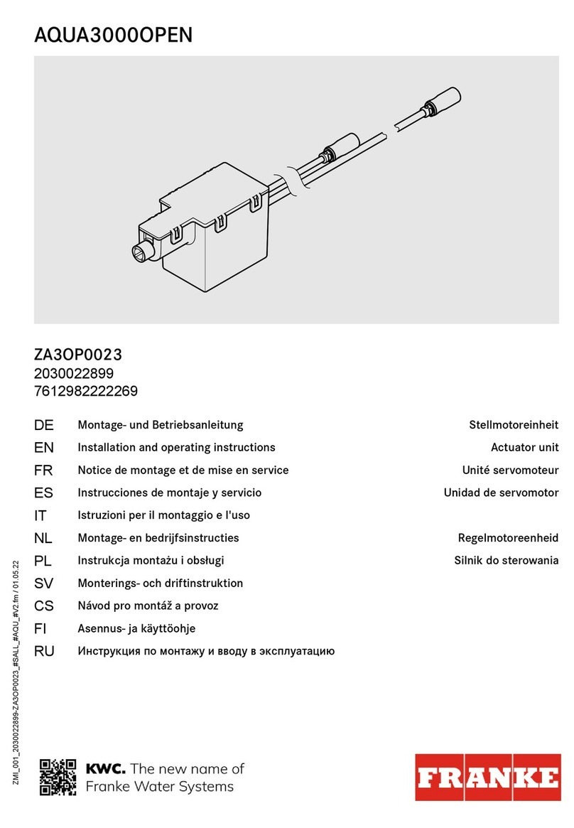
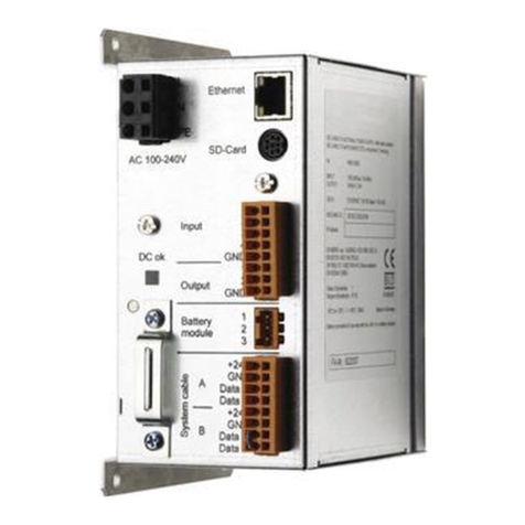
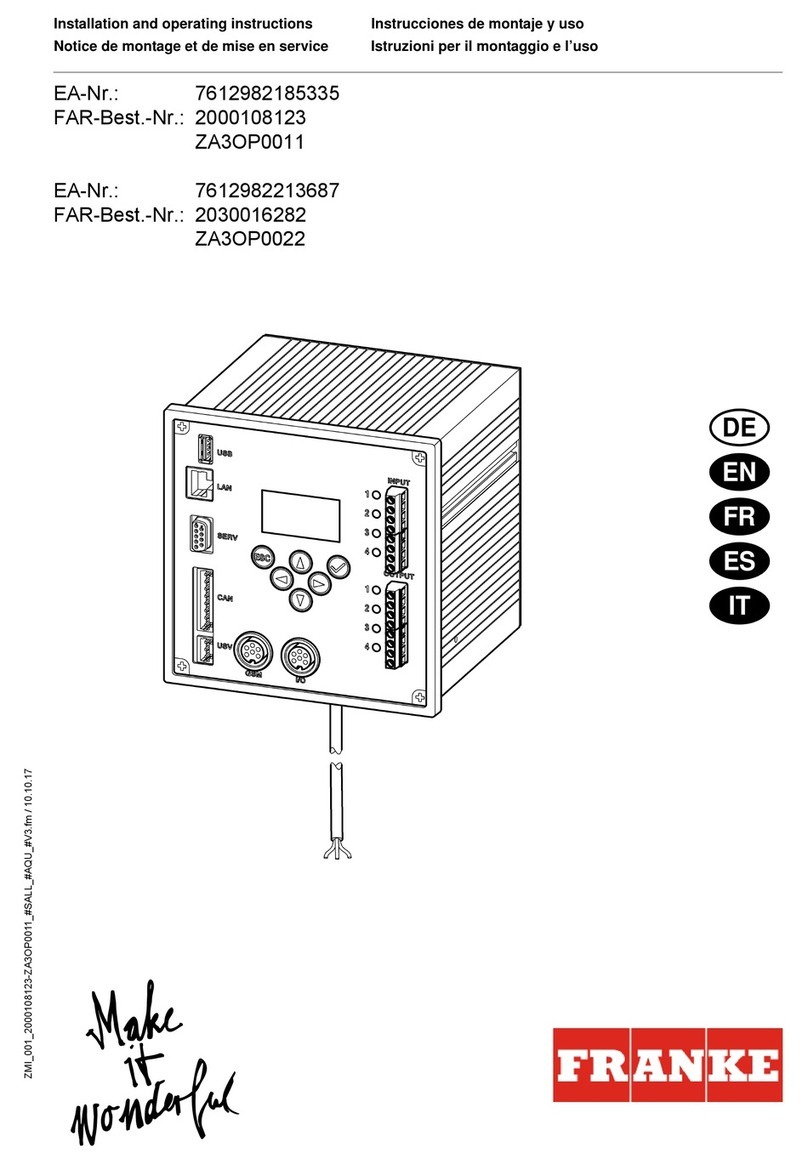
Franke ZA3OP0024 User manual

Installation and operating instructions Montażi instrukcja obsługi
Notice de montage et de mise en service Monterings- og driftsvejledning
Instrucciones de montaje y uso Návod pro montáž a provoz
Istruzioni per il montaggio e l’uso Asennus- ja käyttöohje
Montage- en bedrijfsinstructies Инструкция по монтажу ивводу в
эксплуатацию
ZMI_001_2030025730-ZA3OP0024_#SALL_#AQU_#V1.fm/05.06.15
Franke Aquarotter GmbH, Germany
EA-Nr.: 7612982225604
FAR-Best.-Nr.: 2030025730
ZA3OP0024
DE
EN
FR
ES
IT
NL
PL
SV
CS
FI
RU

2
Inhaltsverzeichnis35.fm
...................................................................................3
Please refer to the graphics in the German Installation and
Operating Instructions.
...................................................................................7
Les graphiques sont disponibles dans la notice de montage et
de mise en service allemande.
...................................................................................11
Por favor, consulte los gráficos en las instrucciones alemanas
de montaje y uso.
...................................................................................15
Per le grafiche fare riferimento alle Istruzioni per il montaggio
e l’uso in tedesco.
...................................................................................19
De tekeningen kunt u in de Duitse montage- en bedrijfsinst-
ructies vinden.
...................................................................................23
Prosimy przyjąć grafikęz niemieckiej instrukcji montażu i
obsługi.
...................................................................................27
Bilderna finns i den tyska monterings- och bruksanvisningen.
...................................................................................31
Obrázky najdete v nìmeckém návodu k montáži a obsluze.
...................................................................................35
Kuvat löydätte saksankielisestä asennus- ja käyttöohjeesta.
...................................................................................39
Рисунки приведены винструкции по монтажу и
эксплуатации на немецком языке.
EN
FR
ES
IT
NL
PL
SV
CS
FI
RU

3
ZMI_001_2030025730-ZA3OP0024_#SEN_#AQU_#V1.fm
0English
Control box for ECC2 function controller
Please refer to the graphics in the German installation and operating instructions.
0Table of contents
1. Abbreviations and units . . . . . . . . . . . . . . . . . . . . . . . . . . . . . . . . 3
2. Key . . . . . . . . . . . . . . . . . . . . . . . . . . . . . . . . . . . . . . . . . . . . . . . . 3
3. Warranty . . . . . . . . . . . . . . . . . . . . . . . . . . . . . . . . . . . . . . . . . . . . 4
4. Important notes. . . . . . . . . . . . . . . . . . . . . . . . . . . . . . . . . . . . . . . 4
Description of product
5. Application . . . . . . . . . . . . . . . . . . . . . . . . . . . . . . . . . . . . . . . . . . 4
6. Technical specifications . . . . . . . . . . . . . . . . . . . . . . . . . . . . . . . . 4
7. Dimensions. . . . . . . . . . . . . . . . . . . . . . . . . . . . . . . . . . . . . . . . . . 4
Assembly, function and commissioning
8. Assembly . . . . . . . . . . . . . . . . . . . . . . . . . . . . . . . . . . . . . . . . . . . 5
9. Function . . . . . . . . . . . . . . . . . . . . . . . . . . . . . . . . . . . . . . . . . . . . 5
1. Abbreviations and units
2. Key
Warning!
Failure to observe can result in bodily injury or even death.
Caution!
Failure to observe can result in material damage.
☞Important!
Failure to observe can cause the product to malfunction.
☞Useful information for optimum handling of the product.
EA-Nr. European article number
FAR-Best.-Nr. Franke Aquarotter order number
Conversion 1 mm = 0.03937 inches
1 inch = 25.4 mm
All length specifications in the graphics are in mm.
EN

4
ZMI_001_2030025730-ZA3OP0024_#SEN_#AQU_#V1.fm
3. Warranty
Liability is accepted in accordance with the General Terms and Conditions of
Business and Supply.
Use only genuine spare parts!
4. Important notes
• Installation, commissioning and maintenance must be performed only by a
qualified expert in accordance with the instructions provided, legal requirements
and recognised engineering standards.
• All technical connection regulations specified by the local water and electricity
supply companies must be observed.
• We reserve the right to make changes.
5. Application
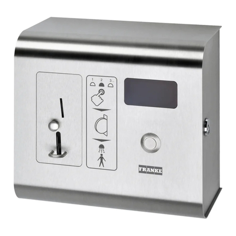
Control box for digital inputs and outputs from the ECC function controller for
triggering the following functions and displays:
– Starting thermal disinfection using a key switch
– Starting cleaning deactivation using a button
– Starting hygiene flush using a button
– Switch between operating mode A and B using a switch
– LED status display for thermal disinfection
– LED collective error message display
6. Technical specifications
7. Dimensions
Operating voltage: 24 V DC
Power consumption: 0.2 W
Protection class: IP 65

5
ZMI_001_2030025730-ZA3OP0024_#SEN_#AQU_#V1.fm
8. Assembly
8.1
Secure the control box (2) to a wall near to the ECC2 function controller (1).
8.2
Connect the control box (2) to the ECC2 function controller (1).
Inputs
a Input 1 - grey
Thermal disinfection
b Input 2 - yellow
Hygiene flush
c Input 3 - green
Cleaning deactivation
dGND-white
Ground for the inputs
e Input 4 - brown
Set switch (A/B)
f Bridge
Bridge these terminals if necessary
Outputs
g Output 1 - red
Thermal disinfection
h Output 2 - pink
Collective error
i GND - blue
Ground for the outputs
k Bridge (+ 24 V)
Bridge these terminals if necessary
9. Function
Hygiene flush start command
9.1
Press the hygiene flush button (1) for at least 5 s.
• If the hygiene flush function and a flow time are defined in the program ID for the
fitting, the hygiene flush starts.
Cleaning circuit start command
9.2
Press the cleaning circuit button (2) for at least 5 s.
• The fittings in the network are switched to cleaning mode. No actuation of fittings
possible.
9.3
Press the cleaning circuit button (2) again.
• Cleaning deactivation is ended.

6
ZMI_001_2030025730-ZA3OP0024_#SEN_#AQU_#V1.fm
Zone switchover
9.4
Move the zone switchover (3).
• This switches between set A and set B for e.g.: Daylight saving time and standard
time, day/night mode or room occupied/unoccupied.
• The function depends on the content of the program ID in the electronics
modules.
Thermal disinfection start command
9.5
Move and hold the key (4).
☞The contact must be closed for at least 5 s and no more than 2 minutes.
LED for thermal disinfection (5)
If thermal disinfection is running, this LED lights up.
☞Normal function: Permanent ON for the duration of the thermal disinfection.
LED for collective error (6)
If there is a general error, this LED lights up.
☞Function for fitting or function collective error: Permanent ON.

7
ZMI_001_2030025730-ZA3OP0024_#SFR_#AQU_#V1.fm
0Français
Boîtier de commande pour contrôleur de fonction ECC2
Les graphiques figurent dans la notice de montage et de mise en service allemande.
0Table des matières
1. Abréviations et unités . . . . . . . . . . . . . . . . . . . . . . . . . . . . . . . . . . 7
2. Pictogrammes. . . . . . . . . . . . . . . . . . . . . . . . . . . . . . . . . . . . . . . . 7
3. Garantie . . . . . . . . . . . . . . . . . . . . . . . . . . . . . . . . . . . . . . . . . . . . 8
4. Remarques importantes . . . . . . . . . . . . . . . . . . . . . . . . . . . . . . . . 8
Description du produit
5. Application . . . . . . . . . . . . . . . . . . . . . . . . . . . . . . . . . . . . . . . . . . 8
6. Caractéristiques techniques . . . . . . . . . . . . . . . . . . . . . . . . . . . . . 8
7. Dimensions. . . . . . . . . . . . . . . . . . . . . . . . . . . . . . . . . . . . . . . . . . 8
Montage, fonctionnement et mise en service
8. Montage . . . . . . . . . . . . . . . . . . . . . . . . . . . . . . . . . . . . . . . . . . . . 9
9. Fonctionnement . . . . . . . . . . . . . . . . . . . . . . . . . . . . . . . . . . . . . . 9
1. Abréviations et unités
2. Pictogrammes
Avertissement !
Un non-respect des consignes est susceptible de présenter un danger de mort ou
de provoquer des blessures.
Attention !
Un non-respect des consignes est susceptible de provoquer des dommages matériels.
☞Important !
Un non-respect des consignes est susceptible de provoquer des dysfonctionne-
ments sur le produit.
☞Informations utiles pour une utilisation optimale du produit.
EA-Nr. Numéro d'article européen
FAR-Best.-Nr. Référence de commande Franke Aquarotter
Conversion 1 mm = 0,03937 pouce
1 pouce = 25,4 mm
Sur les graphiques, toutes les longueurs sont exprimées en mm.
FR

8
ZMI_001_2030025730-ZA3OP0024_#SFR_#AQU_#V1.fm
3. Garantie
La responsabilité est conforme à celle décrite dans les conditions générales de
vente et de livraison.
Utiliser exclusivement des pièces de rechange d'origine !
4. Remarques importantes
• Seul un spécialiste est habilité à procéder au montage, à la mise en service et à
l'entretien de l'installation, et ceci tout en veillant à ce que ces opérations soient
réalisées conformément aux instructions fournies, aux prescriptions légales et
aux règles techniques d'usage.
• Les prescriptions techniques des sociétés d'approvisionnement en eau et en
électricité doivent également être respectées.
• Sous réserve de modifications.
5. Application
Boîtier de commande pour entrées et sorties numériques du contrôleur de fonction
ECC destiné à déclencher les fonctions et affichages suivants :
– Lancement désinfection thermique via commutateur à clé
– Lancement arrêt du nettoyage via bouton-poussoir
– Lancement rinçage hygiénique via bouton-poussoir
– Commutation mode de fonctionnement A / B via commutateur
– Affichage d'état de la désinfection thermique via DEL
– Affichage des dérangements collectifs via DEL
6. Caractéristiques techniques
7. Dimensions
Tension de raccordement : 24 V CC
Puissance absorbée : 0,2 W
Type de protection : IP 65

9
ZMI_001_2030025730-ZA3OP0024_#SFR_#AQU_#V1.fm
8. Montage
8.1
Fixer le boîtier de commande (2) à un mur, à proximité du contrôleur de fonction
ECC2 (1).
8.2
Raccorder le boîtier de commande (2) au contrôleur de fonction ECC2 (1).
Entrées
a Entrée 1 - grise
Désinfection thermique
b Entrée 2 - jaune
Rinçage hygiénique
c Entrée 3 - verte
Arrêt du nettoyage
dTERRE-blanche
Masse pour les entrées
e Entrée 4 - brune
Commutation du mode de fonctionnement (A/B)
fPont
ponter éventuellement ces bornes
Sorties
g Sortie 1 - rouge
Désinfection thermique
h Sortie 2 - rose
Dérangement collectif
i TERRE - bleue
Masse pour les sorties
kPont(+24V)
ponter éventuellement ces bornes
9. Fonctionnement
Commande de lancement du rinçage hygiénique
9.1
Appuyer pendant au moins 5 sec. sur le bouton-poussoir Rinçage hygiénique (1).
• Si la fonctionnalité Rinçage hygiénique et une durée d'écoulement sont enregis-
trées dans la référence du programme de la robinetterie, le rinçage hygiénique
démarre.
Commande de lancement de l'arrêt du nettoyage
9.2
Appuyer pendant au moins 5 sec. sur le bouton-poussoir Arrêt du nettoyage (2).
• La robinetterie du réseau passe alors en mode de nettoyage. Il est alors impos-
sible de déclencher la robinetterie.
9.3
Appuyer de nouveau sur le bouton-poussoir Arrêt du nettoyage (2).
• L'arrêt du nettoyage est alors terminé.

10
ZMI_001_2030025730-ZA3OP0024_#SFR_#AQU_#V1.fm
Commutation de zone
9.4
Tourner le commutateur de commutation de zone (3) en position horizontale.
• Ce commutateur permet de commuter entre les modes de fonctionnement A et B,
p. ex. pour : heure d'été / heure d'hiver, mode jour / nuit ou pièce occupée / non
occupée.
• La fonctionnalité dépend du contenu de la référence du programme au sein des
modules électroniques.
Commande de lancement de la désinfection thermique
9.5
Tourner la clé (4) en position horizontale et la maintenir dans cette position.
☞Le contact doit être fermé pendant une durée minimum de 5 sec. et une durée
maximum de 2 minutes.
DEL de désinfection thermique (5)
Cette DEL s'allume lorsqu'une désinfection thermique a lieu.
☞Fonctionnalité classique : en permanence « ALLUMÉE » durant toute la durée
de la désinfection thermique.
DEL de dérangement collectif (6)
Cette DEL s'allume lorsqu'une erreur générale se présente.
☞Fonctionnalité en cas de dérangement collectif au niveau de la robinetterie, ou
message de dérangement collectif : en permanence « ALLUMÉE ».

11
ZMI_001_2030025730-ZA3OP0024_#SES_#AQU_#V1.fm
0Español
Caja de mando para el controlador de función ECC2
Puede consultar los gráficos en las instrucciones de instalación y funcionamiento
alemanas.
0Índice
1. Abreviaturas y unidades . . . . . . . . . . . . . . . . . . . . . . . . . . . . . . . . 11
2. Aclaración de símbolos . . . . . . . . . . . . . . . . . . . . . . . . . . . . . . . . 11
3. Garantía . . . . . . . . . . . . . . . . . . . . . . . . . . . . . . . . . . . . . . . . . . . . 12
4. Indicaciones importantes . . . . . . . . . . . . . . . . . . . . . . . . . . . . . . . 12
Descripción del producto
5. Aplicación . . . . . . . . . . . . . . . . . . . . . . . . . . . . . . . . . . . . . . . . . . . 12
6. Datos técnicos . . . . . . . . . . . . . . . . . . . . . . . . . . . . . . . . . . . . . . . 12
7. Dimensiones. . . . . . . . . . . . . . . . . . . . . . . . . . . . . . . . . . . . . . . . . 12
Montaje, funcionamiento y puesta en servicio
8. Montaje. . . . . . . . . . . . . . . . . . . . . . . . . . . . . . . . . . . . . . . . . . . . . 13
9. Funcionamiento . . . . . . . . . . . . . . . . . . . . . . . . . . . . . . . . . . . . . . 13
1. Abreviaturas y unidades
2. Aclaración de símbolos
¡Advertencia!
Si no se tiene en cuenta, existe peligro de muerte o de lesiones.
¡Atención!
Si no se tiene en cuenta, se pueden producir daños materiales.
☞¡Importante!
Si no se tiene en cuenta, se pueden producir fallos de funcionamiento en el producto.
☞Información útil para un manejo óptimo del producto.
EA-Nr. Número de artículo europeo
FAR-Best.-Nr. Número de pedido de Franke Aquarotter
Conversión 1 mm = 0,03937 pulgadas
1 pulgada = 25,4 mm
Todos los datos de longitudes de los gráficos se indican en mm.
ES

12
ZMI_001_2030025730-ZA3OP0024_#SES_#AQU_#V1.fm
3. Garantía
La responsabilidad se asume según las condiciones generales comerciales y de
suministro.
¡Utilizar únicamente piezas de repuesto originales!
4. Indicaciones importantes
• La instalación, la puesta en servicio y el mantenimiento deben ser efectuados
únicamente por personal especializado y según las instrucciones suministradas,
de conformidad con la normativa local vigente y las buenas prácticas de
ingeniería.
• Cumplir las condiciones de conexión de la empresa de suministro de agua y
energía local.
• Reservado el derecho a realizar modificaciones.
5. Aplicación
Caja de mando para entradas y salidas digitales del controlador de función ECC
para la activación de las siguientes funciones e indicaciones:
– inicio de la desinfección térmica por medio de interruptor de llave
– inicio de la desconexión de limpieza por medio de pulsador
– inicio del enjuague higiénico por medio de pulsador
– conmutación entre modos de funcionamiento A / B por medio de interruptor
– indicación del estado de la desinfección térmica mediante LED
– indicación de avería general mediante LED
6. Datos técnicos
7. Dimensiones
Tensión de conexión: 24 V CC
Consumo de potencia: 0,2 W
Grado de protección: IP 65

13
ZMI_001_2030025730-ZA3OP0024_#SES_#AQU_#V1.fm
8. Montaje
8.1
Fijar la caja de mando (2) a una pared cerca del controlador de función ECC2 (1).
8.2
Conectar la caja de mando (2) al controlador de función ECC2 (1).
Entradas
a Entrada 1 - gris
desinfección térmica
b Entrada 2 - amarilla
enjuague higiénico
c Entrada 3 - verde
desconexión de limpieza
d GND - blanca
tierra para las entradas
e Entrada 4 - marrón
conmutación de conjunto (A/B)
f Puente
puentear estos terminales en caso necesario
Salidas
g Salida 1 - roja
desinfección térmica
h Salida 2 - rosa
avería general
iGND-azul
tierra para las salidas
k Puente (+ 24 V)
puentear estos terminales en caso necesario
9. Funcionamiento
Orden de inicio de enjuague higiénico
9.1
Presionar el pulsador de enjuague higiénico (1) durante 5 s como mínimo.
• Si a la ID del programa de la grifería está asignada la funcionalidad enjuague
higiénico con un tiempo de flujo, dará inicio el enjuague higiénico.
Orden de inicio de conexión de limpieza
9.2
Presionar el pulsador de conexión de limpieza (2) durante 5 s como mínimo.
• Las griferías de la red se activarán en el modo de limpieza. No es posible activar
las griferías.
9.3
Presionar de nuevo el pulsador de conexión de limpieza (2).
• La desconexión de limpieza finalizará.

14
ZMI_001_2030025730-ZA3OP0024_#SES_#AQU_#V1.fm
Conmutación de zonas
9.4
Accionar el interruptor de conmutación de zonas (3).
• Conmuta entre el conjunto A o B para elegir entre, por ejemplo: horario de
verano/invierno, modo diurno/nocturno o habitación asignada/no asignada.
• La funcionalidad depende del contenido de la ID del programa dentro de los
módulos electrónicos.
Orden de inicio de desinfección térmica
9.5
Girar y mantener la llave (4).
☞El contacto debe estar cerrado durante 5 s como mínimo y 2 minutos como
máximo.
LED de desinfección térmica (5)
Cuando se lleva a cabo una desinfección térmica, se ilumina el LED.
☞Funcionalidad normal: "ON" permanente durante la desinfección térmica.
LED de avería general (6)
Cuando aparece un fallo general, se ilumina el LED.
☞Funcionalidad en caso de avería en griferías y funcionalidad en caso de avería
general: "ON" permanente.

15
ZMI_001_2030025730-ZA3OP0024_#SIT_#AQU_#V1.fm
0Italiano
Scatola di comando per controller ECC2
Per le figure consultare le istruzioni di montaggio e uso in tedesco.
0Indice
1. Abbreviazioni e unità . . . . . . . . . . . . . . . . . . . . . . . . . . . . . . . . . . 15
2. Spiegazione dei simboli . . . . . . . . . . . . . . . . . . . . . . . . . . . . . . . . 15
3. Garanzia. . . . . . . . . . . . . . . . . . . . . . . . . . . . . . . . . . . . . . . . . . . . 16
4. Indicazioni importanti . . . . . . . . . . . . . . . . . . . . . . . . . . . . . . . . . . 16
Descrizione del prodotto
5. Impiego. . . . . . . . . . . . . . . . . . . . . . . . . . . . . . . . . . . . . . . . . . . . . 16
6. Dati tecnici . . . . . . . . . . . . . . . . . . . . . . . . . . . . . . . . . . . . . . . . . . 16
7. Misure. . . . . . . . . . . . . . . . . . . . . . . . . . . . . . . . . . . . . . . . . . . . . . 16
Montaggio, funzionamento e messa in servizio
8. Montaggio. . . . . . . . . . . . . . . . . . . . . . . . . . . . . . . . . . . . . . . . . . . 17
9. Funzionamento. . . . . . . . . . . . . . . . . . . . . . . . . . . . . . . . . . . . . . . 17
1. Abbreviazioni e unità
2. Spiegazione dei simboli
Avvertenza!
La mancata osservanza può comportare pericolo di morte o lesioni.
Attenzione!
La mancata osservanza può comportare danni materiali.
☞Importante!
La mancata osservanza può comportare anomalie nel funzionamento del prodotto.
☞Informazioni utili per l'uso ottimale del prodotto.
EA-Nr. Codice articolo europeo
FAR-Best.-Nr. Codice ordinazione Franke Aquarotter
Conversione 1 mm = 0,03937 pollici
1 pollice = 25,4 mm
Tutte le indicazioni di lunghezza nelle figure sono in mm.
IT

16
ZMI_001_2030025730-ZA3OP0024_#SIT_#AQU_#V1.fm
3. Garanzia
La responsabilità viene assunta in conformità alle condizioni generali di vendita e
fornitura.
Utilizzare solo ricambi originali!
4. Indicazioni importanti
• Per il montaggio, la messa in servizio e la manutenzione incaricare solo un
tecnico specializzato, nel rispetto delle istruzioni fornite, delle norme di legge e
delle norme tecniche riconosciute.
• Attenersi alle disposizioni tecniche di allacciamento degli enti erogatori di acqua
ed energia locali.
• Con riserva di modifiche.
5. Impiego
Scatola di comando per gli ingressi e le uscite digitali del controller ECC usati per
l’attivazione delle seguenti funzioni e indicazioni:
– Avvio disinfezione termica mediante interruttore a chiave
– Avvio spegnimento per pulizia mediante pulsante
– Avvio lavaggio igienico mediante pulsante
– Commutazione modalità operativa A / B mediante interruttore
– Indicazione di stato della disinfezione termica tramite LED
– Segnalazione di errore cumulativo tramite LED
6. Dati tecnici
7. Misure
Tensione di collegamento: 24 V CC
Potenza assorbita: 0,2 W
Tipo di protezione: IP 65

17
ZMI_001_2030025730-ZA3OP0024_#SIT_#AQU_#V1.fm
8. Montaggio
8.1
Fissare la scatola di comando (2) ad una parete nei pressi del controller ECC2 (1).
8.2
Collegare la scatola di comando (2) al controller ECC2 (1).
Ingressi
a Ingresso 1 - grigio
Disinfezione termica
b Ingresso 2 - giallo
Lavaggio igienico
c Ingresso 3 - verde
Spegnimento per pulizia
d GND - bianco
Massa per gli ingressi
e Ingresso 4 - marrone
Commutazione set (A/B)
fPonticello
Ponticellare eventualmente questi morsetti
Uscite
g Uscita 1 - rosso
Disinfezione termica
h Uscita 2 - rosa
Errore cumulativo
i GND - blu
Massa per le uscite
k Ponticello (+ 24 V)
Ponticellare eventualmente questi morsetti
9. Funzionamento
Comando di avvio lavaggio igienico
9.1
Premere per min. 5 secondi il pulsante Lavaggio igienico (1).
• Se nell’ID programma dell’apparecchio sono memorizzate la funzionalità
Lavaggio igienico e la durata del flusso, inizia il lavaggio igienico.
Comando di avvio spegnimento per pulizia
9.2
Premere per min. 5 secondi il pulsante Spegnimento per pulizia (2).
• Gli apparecchi della rete passano alla modalità di pulizia. Non è possibile attivare
gli apparecchi.
9.3
Premere nuovamente il pulsante Spegnimento per pulizia (2).
• Lo spegnimento per pulizia finisce.

18
ZMI_001_2030025730-ZA3OP0024_#SIT_#AQU_#V1.fm
Commutazione zone
9.4
Azionare l’interruttore Commutazione zone (3).
• Consente di alternare tra il set A e il set B, ad es. per: ora legale/ora solare,
modalità diurna/notturna o stanza occupata/non occupata.
• La funzionalità dipende dal contenuto degli ID programma nei moduli elettronici.
Comando di avvio disinfezione termica
9.5
Girare e tenere girata la chiave (4).
☞Il contatto deve restare chiuso per minimo 5 secondi e massimo 2 minuti.
LED disinfezione termica (5)
Il LED resta acceso mentre è in corso una disinfezione termica.
☞Funzionalità normale: permanentemente acceso per la durata della disinfe-
zione termica.
LED errore cumulativo (6)
Il LED si accende in presenza di un errore generale.
☞Funzionalità per errore cumulativo degli apparecchi o della funzionalità: perma-
nentemente acceso.

19
ZMI_001_2030025730-ZA3OP0024_#SNL_#AQU_#V1.fm
0Nederlands
Bedieningsbox voor ECC2-functiecontroller
De tekeningen kunt u vinden in de Duitstalige montage- en gebruikshandleiding.
0Inhoudsopgave
1. Afkortingen en eenheden . . . . . . . . . . . . . . . . . . . . . . . . . . . . . . . 19
2. Verklaring van de symbolen . . . . . . . . . . . . . . . . . . . . . . . . . . . . . 19
3. Garantie . . . . . . . . . . . . . . . . . . . . . . . . . . . . . . . . . . . . . . . . . . . . 20
4. Belangrijke aanwijzingen . . . . . . . . . . . . . . . . . . . . . . . . . . . . . . . 20
Productbeschrijving
5. Toepassing . . . . . . . . . . . . . . . . . . . . . . . . . . . . . . . . . . . . . . . . . . 20
6. Technische gegevens . . . . . . . . . . . . . . . . . . . . . . . . . . . . . . . . . . 20
7. Afmetingen . . . . . . . . . . . . . . . . . . . . . . . . . . . . . . . . . . . . . . . . . . 20
Montage, werking en inbedrijfstelling
8. Montage . . . . . . . . . . . . . . . . . . . . . . . . . . . . . . . . . . . . . . . . . . . . 21
9. Werking . . . . . . . . . . . . . . . . . . . . . . . . . . . . . . . . . . . . . . . . . . . . 21
1. Afkortingen en eenheden
2. Verklaring van de symbolen
Waarschuwing!
Veronachtzaming van de instructie kan levensgevaar of lichamelijk letsel veroorzaken.
Attentie!
Veronachtzaming van de instructie kan materiële schade veroorzaken.
☞Belangrijk!
Veronachtzaming van de instructie kan storingen in de werking van het product
veroorzaken.
☞Nuttige informatie voor een optimale behandeling van het product.
EA-Nr. Europees artikelnummer
FAR-Best.-Nr. Franke Aquarotter-bestelnummer
Omrekening 1 mm = 0,03937 inch
1 inch = 25,4 mm
Alle lengtegegevens in tekeningen zijn in mm aangegeven.
NL

20
ZMI_001_2030025730-ZA3OP0024_#SNL_#AQU_#V1.fm
3. Garantie
Met betrekking tot aansprakelijkheid gelden de algemene leverings- en handelsvoor-
waarden.
Uitsluitend originele reserveonderdelen gebruiken!
4. Belangrijke aanwijzingen
• Montage, inbedrijfstelling en onderhoud mogen alleen door een vakman volgens
de meegeleverde instructies en volgens de wettelijke voorschriften en erkende
regels van de techniek worden uitgevoerd.
• De technische voorwaarden voor aansluiting van de plaatselijke water- en
energiebedrijven moeten in acht worden genomen.
• Wijzigingen voorbehouden.
5. Toepassing
Bedieningsbox voor digitale in- en uitgangen van de ECC-functiecontroller met het
oog op de activering van de volgende functies en indicatoren:
– Start thermische desinfectie d.m.v. sleuteltoets
– Start reinigingsuitschakeling d.m.v. toets
– Start hygiënische spoeling d.m.v. toets
– Omschakeling bedrijfsmodus A / B d.m.v. schakelaar
– Statusindicator van de thermische desinfectie via led
– Verzamelstoringsmeldingsindicator via led
6. Technische gegevens
7. Afmetingen
Aansluitspanning: 24 V DC
Opgenomen vermogen: 0,2 W
Veiligheidsklasse: IP 65
This manual suits for next models
1
Table of contents
Languages:
Other Franke Controllers manuals

Franke
Franke AQUA802 User manual

Franke
Franke ECC2 Function Controller User manual

Franke
Franke AQUA3000OPEN ZA3OP0023 User manual

Franke
Franke ZAQUA005 User manual

Franke
Franke GMKPc JKL Series User manual

Franke
Franke ZA3OP0034 User manual

Franke
Franke Protronic A3000 open User manual

Franke
Franke AQUA802 User manual
Popular Controllers manuals by other brands

Mitsubishi
Mitsubishi QCPU (Q Mode) user manual

Cleco
Cleco DGD mPro400GC Programming manual

Smartgen
Smartgen HFC6100LT user manual

Broadcast Pix
Broadcast Pix VOX Operator's manual

Tech Controllers
Tech Controllers EU-24 SIGMA user manual

Dungs
Dungs hiltbrand DGAI. 69F Customer's operating and assembly instructions