manuals.online logo
Brands
  1. Home
  2. •
  3. Brands
  4. •
  5. Emerson
  6. •
  7. Controllers
  8. •
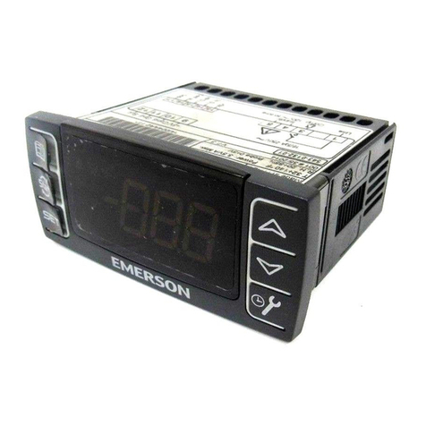
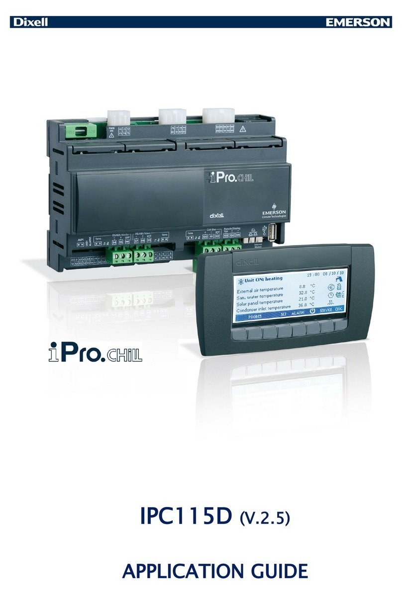
  9. Emerson iPro Series Wiring diagram

Emerson iPro Series Wiring diagram

This manual suits for next models

2

Other Emerson Controllers manuals

Emerson Fisher Fieldvue DVC6030f User manual

Emerson

Emerson Fisher Fieldvue DVC6030f User manual

Emerson FISHER 66 User manual

Emerson

Emerson FISHER 66 User manual

Emerson FISHER FIELDVUE DLC3010 User manual

Emerson

Emerson FISHER FIELDVUE DLC3010 User manual

Emerson Branson 2000X ae User manual

Emerson

Emerson Branson 2000X ae User manual

Emerson CASH VALVE B-95 Manual

Emerson

Emerson CASH VALVE B-95 Manual

Emerson CASH VALVE B Series Manual

Emerson

Emerson CASH VALVE B Series Manual

Emerson FXMP25 User manual

Emerson

Emerson FXMP25 User manual

Emerson Vilter MicroVission Operation manual

Emerson

Emerson Vilter MicroVission Operation manual

Emerson Fisher 1078 User manual

Emerson

Emerson Fisher 1078 User manual

Emerson AW Series User manual

Emerson

Emerson AW Series User manual

Emerson Keystone EPI2 User manual

Emerson

Emerson Keystone EPI2 User manual

Emerson Dixell XR75CX Series User manual

Emerson

Emerson Dixell XR75CX Series User manual

Emerson Fisher 299H User manual

Emerson

Emerson Fisher 299H User manual

Emerson 2000LP Series User manual

Emerson

Emerson 2000LP Series User manual

Emerson dixell XR60CX Wiring diagram

Emerson

Emerson dixell XR60CX Wiring diagram

Emerson Dixell XR70CX Wiring diagram

Emerson

Emerson Dixell XR70CX Wiring diagram

Emerson Fisher FIELDVUE DVC6005 Series User manual

Emerson

Emerson Fisher FIELDVUE DVC6005 Series User manual

Emerson Bettis G01 Series Installation instructions

Emerson

Emerson Bettis G01 Series Installation instructions

Emerson Fisher FIELDVUE DLC3020f User manual

Emerson

Emerson Fisher FIELDVUE DLC3020f User manual

Emerson Fisher 1098-EGR User manual

Emerson

Emerson Fisher 1098-EGR User manual

Emerson Double-Acting Series Installation instructions

Emerson

Emerson Double-Acting Series Installation instructions

Emerson Fisher EZR series User manual

Emerson

Emerson Fisher EZR series User manual

Emerson Fisher FIELDVUE DVC6200 SIS Configuration guide

Emerson

Emerson Fisher FIELDVUE DVC6200 SIS Configuration guide

Emerson P159A Series Installation and operating instructions

Emerson

Emerson P159A Series Installation and operating instructions

Popular Controllers manuals by other brands

Sunricher SR-ZV9003T3-RGBW-US Installation

Sunricher

Sunricher SR-ZV9003T3-RGBW-US Installation

Ksenia intro Installation and configuration manual

Ksenia

Ksenia intro Installation and configuration manual

Inovance CAN200 Series manual

Inovance

Inovance CAN200 Series manual

Gauzy LC6 FLEX Controller Installation and operation guide

Gauzy

Gauzy LC6 FLEX Controller Installation and operation guide

Viking SLP-1 Technical practice

Viking

Viking SLP-1 Technical practice

CKD KBX-30E-U Series instruction manual

CKD

CKD KBX-30E-U Series instruction manual

Sharp Energy Sun Flux User manual & installation guide

Sharp Energy

Sharp Energy Sun Flux User manual & installation guide

Yamaha RCX40 user manual

Yamaha

Yamaha RCX40 user manual

AB Quality PowerFlex 400 Frames D-H Service bulletin

AB Quality

AB Quality PowerFlex 400 Frames D-H Service bulletin

Yamaha MJC8 owner's manual

Yamaha

Yamaha MJC8 owner's manual

AL-KO ATC operating instructions

AL-KO

AL-KO ATC operating instructions

Savant SmartControl 2 Deployment guide

Savant

Savant SmartControl 2 Deployment guide

GameSir T3S user manual

GameSir

GameSir T3S user manual

Kostal inveor operating manual

Kostal

Kostal inveor operating manual

CoCo ACM-LV24 Quick installation guide

CoCo

CoCo ACM-LV24 Quick installation guide

Brooks SLA5810/20 Installation and operation manual

Brooks

Brooks SLA5810/20 Installation and operation manual

SIGMA TEK SR 011 Technical manual

SIGMA TEK

SIGMA TEK SR 011 Technical manual

Aprilaire 76 installation instructions

Aprilaire

Aprilaire 76 installation instructions

manuals.online logo
manuals.online logoBrands
  • About & Mission
  • Contact us
  • Privacy Policy
  • Terms and Conditions

Copyright 2025 Manuals.Online. All Rights Reserved.

iPro SERIES
(v.3.5)
1592025700 IPROFAMILY 3.5 stp GB 2016.12.07 iPro Series 2/96
INDEX
1. IMPORTANT RECOMMENDATIONS 5
1.1 PRODUCT DISPOSAL (WEEE) 6
2. INTRODUCTION 7
3. GENERAL SPECIFICATIONS 7
3.1 PROCESSING ENVIRONMENT 7
3.1.1 Fields of application............................................................................................................................................................7
3.1.2 Hardware architecture........................................................................................................................................................7
3.2 RELEVANT DATA 8
4. VERSIONS OF THE PROGRAMMABLE CONTROLLERS 9
4.1 IPRO.GENIUS AND IPRO.CHILL (IPG100D – IPC100D RANGES) 10
4.1.1 Description of the connections..........................................................................................................................................11
4.1.2 Description of the inputs and outputs................................................................................................................................12
4.1.3 Technical specifications....................................................................................................................................................14
4.1.3.1 Analogue inputs.......................................................................................................................................................14
4.1.3.2 Digital inputs............................................................................................................................................................14
4.1.3.3 Analogue outputs.....................................................................................................................................................14
4.1.3.4 Standard Digital outputs...........................................................................................................................................15
4.1.3.5 SSR Digital outputs version .....................................................................................................................................15
4.1.3.6 Wiring diagrams.......................................................................................................................................................15
4.1.3.7 Mechanical specifications........................................................................................................................................16
4.1.3.8 Electrical specifications............................................................................................................................................16
4.1.3.9 Plastic container......................................................................................................................................................16
4.1.3.10 Product certifications ...............................................................................................................................................17
4.2 IPRO.GENIUS (IPG200D RANGE) 18
4.2.1 Description of the connections..........................................................................................................................................18
4.2.2 Description of the inputs and outputs................................................................................................................................19
4.2.3 Technical specifications....................................................................................................................................................21
4.2.3.1 Analogue inputs.......................................................................................................................................................21
4.2.3.2 Digital inputs............................................................................................................................................................21
4.2.3.3 Analogue outputs.....................................................................................................................................................21
4.2.3.4 Digital outputs..........................................................................................................................................................22
4.2.3.5 Wiring diagrams.......................................................................................................................................................22
4.2.3.6 Mechanical specifications........................................................................................................................................23
4.2.3.7 Electrical specifications............................................................................................................................................23
4.2.3.8 Plastic container......................................................................................................................................................23
4.2.3.9 Product certifications ...............................................................................................................................................23
4.3 IPRO.GENIUS AND IPRO.CHILL (IPG300D – IPC300D RANGES) 24
4.3.1 Description of the connections..........................................................................................................................................25
4.3.2 Description of the inputs and outputs................................................................................................................................26
4.3.3 Technical specifications....................................................................................................................................................28
4.3.3.1 Analogue inputs.......................................................................................................................................................28
4.3.3.2 Digital inputs............................................................................................................................................................28
4.3.3.3 Analogue outputs.....................................................................................................................................................28
4.3.3.4 Standard Digital outputs...........................................................................................................................................29
4.3.3.5 Wiring diagrams.......................................................................................................................................................29
4.3.3.6 Mechanical specifications........................................................................................................................................30
4.3.3.7 Electrical specifications............................................................................................................................................30
4.3.3.8 Plastic container......................................................................................................................................................30
4.3.3.9 Product certifications ...............................................................................................................................................30
4.4 IPRO.GENIUS (IPG800D RANGES) 31
4.4.1 Description of the connections..........................................................................................................................................31
4.4.2 Description of the inputs and outputs................................................................................................................................32
4.4.3 Technical specifications....................................................................................................................................................33
4.4.3.1 Analogue inputs.......................................................................................................................................................33
4.4.3.2 Digital inputs............................................................................................................................................................34
4.4.3.3 Analogue outputs.....................................................................................................................................................34
4.4.3.4 Digital outputs..........................................................................................................................................................34
4.4.3.5 Wiring diagrams.......................................................................................................................................................35
4.4.3.6 Mechanical specifications........................................................................................................................................35
4.4.3.7 Electrical specifications............................................................................................................................................35
4.4.3.8 Plastic container......................................................................................................................................................36
4.4.3.9 Product certifications ...............................................................................................................................................36
4.5 IPRO 4 DIN (IPG100D – IPG200D – IPC100E RANGES) 37
4.5.1 Description of the connections..........................................................................................................................................38
4.5.2 Description of the inputs and outputs................................................................................................................................38
4.5.3 Technical specifications....................................................................................................................................................39
4.5.3.1 Analogue inputs.......................................................................................................................................................39
1592025700 IPROFAMILY 3.5 stp GB 2016.12.07 iPro Series 3/96
4.5.3.2 Digital inputs............................................................................................................................................................39
4.5.3.3 Analogue outputs.....................................................................................................................................................40
4.5.3.4 Digital outputs..........................................................................................................................................................40
4.5.3.5 Wiring diagrams.......................................................................................................................................................40
4.5.3.6 Mechanical specifications........................................................................................................................................41
4.5.3.7 Electrical specifications............................................................................................................................................41
4.5.3.8 Plastic container......................................................................................................................................................41
4.5.3.9 USB-ETHERNET Adapter (Dixell specification).......................................................................................................41
4.6 IPRO.LINK (IPL500D) 42
4.6.1 Description of the connections..........................................................................................................................................42
4.6.2 Description of the inputs and outputs................................................................................................................................43
4.6.3 Technical specifications....................................................................................................................................................43
4.6.3.1 Wiring diagrams.......................................................................................................................................................43
4.6.3.2 Mechanical specifications........................................................................................................................................44
4.6.3.3 Electrical specifications............................................................................................................................................44
4.6.3.4 Plastic container......................................................................................................................................................44
4.7 IPX106D 45
4.7.1 Description of the connections..........................................................................................................................................45
4.7.2 Description of the inputs and outputs................................................................................................................................46
4.7.3 Technical specifications....................................................................................................................................................47
4.7.3.1 Analogue inputs.......................................................................................................................................................47
4.7.3.2 Digital inputs............................................................................................................................................................47
4.7.3.3 Analogue outputs.....................................................................................................................................................47
4.7.3.4 Digital outputs..........................................................................................................................................................47
4.7.3.5 Wiring diagrams.......................................................................................................................................................48
4.7.3.6 Mechanical specifications........................................................................................................................................48
4.7.3.7 Electrical specifications............................................................................................................................................48
4.7.3.8 Plastic container......................................................................................................................................................49
4.7.3.9 Setting the address of the device.............................................................................................................................49
4.8 IPX206D – IPX306D 50
4.8.1 Description of the connections..........................................................................................................................................50
4.8.2 Description of the inputs and outputs................................................................................................................................51
4.8.3 Technical specifications....................................................................................................................................................52
4.8.3.1 Analogue inputs.......................................................................................................................................................52
4.8.3.2 Digital inputs............................................................................................................................................................52
4.8.3.3 Analogue outputs.....................................................................................................................................................52
4.8.3.4 Digital outputs..........................................................................................................................................................52
4.8.3.5 Wiring diagrams.......................................................................................................................................................53
4.8.3.6 Mechanical specifications........................................................................................................................................53
4.8.3.7 Electrical specifications............................................................................................................................................54
4.8.3.8 Plastic container ......................................................................................................................................................54
4.8.3.9 Setting the address of the device.............................................................................................................................54
4.9 IPX115D – IPX125D 55
4.9.1 Description of the connections..........................................................................................................................................55
4.9.2 Description of the inputs and outputs................................................................................................................................56
4.9.3 Technical specifications....................................................................................................................................................58
4.9.3.1 Analogue inputs.......................................................................................................................................................58
4.9.3.2 Digital inputs............................................................................................................................................................58
4.9.3.3 Analogue outputs.....................................................................................................................................................58
4.9.3.4 Digital outputs..........................................................................................................................................................59
4.9.3.5 Wiring diagrams.......................................................................................................................................................59
4.9.3.6 Mechanical specifications........................................................................................................................................60
4.9.3.7 Electrical specifications............................................................................................................................................60
4.9.3.8 Plastic container......................................................................................................................................................60
4.9.3.9 Setting the address of the device.............................................................................................................................60
4.10 IPX215D – IPX225D 61
4.10.1 Description of the connections .....................................................................................................................................61
4.10.2 Description of the inputs and outputs ...........................................................................................................................62
4.10.3 Technical specifications ...............................................................................................................................................64
4.10.3.1 Analogue inputs.......................................................................................................................................................64
4.10.3.2 Digital inputs............................................................................................................................................................64
4.10.3.3 Analogue outputs.....................................................................................................................................................64
4.10.3.4 Digital outputs..........................................................................................................................................................65
4.10.3.5 Wiring diagrams.......................................................................................................................................................65
4.10.3.6 Mechanical specifications........................................................................................................................................66
4.10.3.7 Electrical specifications............................................................................................................................................66
4.10.3.8 Plastic container......................................................................................................................................................66
4.10.3.9 Setting the address of the device.............................................................................................................................66
4.11 IPX315D 67
4.11.1 Description of the connections .....................................................................................................................................67
4.11.2 Description of the inputs and outputs ...........................................................................................................................68
4.11.3 Technical specifications ...............................................................................................................................................70
4.11.3.1 Analogue inputs.......................................................................................................................................................70
4.11.3.2 Digital inputs............................................................................................................................................................70
4.11.3.3 Analogue outputs.....................................................................................................................................................70
4.11.3.4 Digital outputs..........................................................................................................................................................71
4.11.3.5 Wiring diagrams.......................................................................................................................................................71
4.11.3.6 Mechanical specifications........................................................................................................................................72
4.11.3.7 Electrical specifications............................................................................................................................................72
4.11.3.8 Plastic container......................................................................................................................................................72
1592025700 IPROFAMILY 3.5 stp GB 2016.12.07 iPro Series 4/96
4.11.3.9 Setting the address of the device.............................................................................................................................72
5. INTERFACE 73
5.1 VISOGRAPH 73
5.1.1 Specifications...................................................................................................................................................................73
5.1.2 Connections.....................................................................................................................................................................74
5.1.3 Options menu...................................................................................................................................................................74
5.1.4 Dimensions ......................................................................................................................................................................75
6. MEANING OF THE LEDS AND JUMPERS IN THE VARIOUS DEVICES 76
6.1 PROGRAMMABLE CONTROLLERS 76
6.2 EXPANSION MODULES 76
7. INSTALLATION 77
7.1 GENERAL RULES 77
7.2 POWER SUPPLY 77
7.3 CONNECTION OF THE ANALOGUE INPUTS 78
7.3.1 Temperature probes (NTC and PTC)................................................................................................................................78
7.3.2 Temperature probes IPG800 Series (NTC, PTC and PT1000)..........................................................................................78
7.3.3 Pressure transducers and current probes (0 - 20mA, 4 - 20mA) .......................................................................................79
7.3.4 Pressure transducers and current probes IPG800 Series (0 - 20mA, 4 - 20mA) ...............................................................79
7.3.5 Pressure transducers and ratiometric pressure transducers (0 - 5V).................................................................................80
7.3.6 Pressure transducers and ratiometric pressure transducers IPG800 Series (0 - 5V).........................................................80
7.3.7 Live probes (0 - 1V, 0 - 5V, 0 - 10V) .................................................................................................................................81
7.3.8 Live probes IPG800 Series (0 - 1V, 0 - 5V, 0 - 10V)..........................................................................................................81
7.3.9 Probes and transducers with 24Vac/dc power supply.......................................................................................................82
7.3.10 Probes and transducers with 24Vac/dc power supply IPG800 Series...........................................................................83
7.4 CONNECTION OF THE DIGITAL INPUTS 84
7.4.1 Potential-free digital inputs ...............................................................................................................................................84
7.4.2 Potential-free digital inputs IPG800 Series........................................................................................................................85
7.4.3 Live digital inputs (24Vac/dc)............................................................................................................................................85
7.4.4 Power supply 24Vac digital inputs IPG800 Series ............................................................................................................86
7.5 CONNECTION OF THE ANALOGUE OUTPUTS 87
7.5.1 0 - 10V, 4 - 20mA Analogue output for condensation control ............................................................................................87
7.5.2 0-10Vdc, 4-20mA Analogue output for fan speed control IPG800 Series..........................................................................88
7.5.3 PWM analogue output for condensation control................................................................................................................88
7.5.4 PWM analogue output for control IPG800 Series..............................................................................................................89
7.5.5 0 - 10V, 4 - 20mA Proportional analogue output for servomotors/actuators ......................................................................89
7.5.6 Devices with 24Vac/dc power supply................................................................................................................................90
7.5.7 Analogue output for relays (coil power supply 12Vdc).......................................................................................................91
7.6 CONNECTION OF THE DIGITAL OUTPUTS 91
7.7 ELECTRONIC EXPANSION VALVE DRIVER IPG800 SERIES 91
7.7.1 GENERAL RULES ...........................................................................................................................................................91
7.7.2 ELECTRICAL CONNECTIONS........................................................................................................................................92
7.8 CANBUS CONNECTION 93
7.9 RS485 SLAVE CONNECTIONS 94
7.10 RS485 MASTER CONNECTION 95
1592025700 IPROFAMILY 3.5 stp GB 2016.12.07 iPro Series 5/96
1. IMPORTANT RECOMMENDATIONS
The symbol alerts the user of non-insulated “dangerous voltage” within the product area that
is sufficiently high to constitute a risk of electric shock to persons.
The symbol alerts the user of important operating and maintenance (assistance) instructions
found in the documentation attached to the device.
Dixell Srl cannot accept any liability for damages caused by modems that are not supported. Dixell
Srl reserves the right to modify this manual without prior notice. The documentation can be
downloaded from www.dixell.com even prior to purchase.
This manual forms part of the product and must always be kept near the device for easy and quick
reference. The device cannot be used as a safety device. Verify the limits of application before using
the device.
Verify that the power supply voltage is correct before connecting the device. Do not expose it to
water or humidity: use the controller only within the operating limits, avoiding sudden changes in
temperature and high atmospheric humidity in order to prevent condensation from forming.
Recommendation: disconnect all the electric connections before performing any maintenance. Insert
the probe where it cannot be reached by the End User. The device must not be opened. Consider
the maximum current that can be applied to each relay. Make sure that the wires for the probes, the
loads and the electrical power supply are separated and sufficiently distant from each other, without
crossing or intertwining with each other. In the case of applications in industrial environments, it may
be useful to use the main filters (our mod. FT1) in parallel to the inductive loads.
The customer shall bear full responsibility and risk for product configuration in order to achieve the
results pertaining to installation and/or final equipment/system. Upon the customer's request and
following a specific agreement, Dixell s.r.l. may be present during the start-up of the final
machine/application, as a consultant, however, under no circumstances can the company be held
responsible for the correct operation of the final equipment/system.
Since Dixell products form part of a very high level of technology, a
qualification/configuration/programming/commissioning stage is required to use them as best as
possible. Otherwise, these products may malfunction and Dixell cannot be held responsible. The
product must not be used in any way that differs from that stipulated in the documentation.
•The device must always be inserted inside an electrical panel that can only be accessed by
authorised personnel. For safety purposes, the keyboard must be the only part that can be reached.
•The device must never be hand-held while being used.
It is good practice to bear the following in mind for all Dixell products:
oPrevent the electronic circuits from getting wet as contact made with water, humidity or any
other type of liquid can damage them. Comply with the temperature and humidity limits
specified in the manual in order to store the product correctly.
oThe device must not be installed in particularly hot environments as high temperatures can
damage it (electronic circuits and/or plastic components forming part of the casing). Comply
with the temperature and humidity limits specified in the manual in order to store the product
correctly.
oUnder no circumstances is the device to be opened - the user does not require the internal
components. Please contact qualified service personnel for any assistance.
1592025700 IPROFAMILY 3.5 stp GB 2016.12.07 iPro Series 6/96
oPrevent the device from being dropped, knocked or shaken as either can cause irreparable
damage.
oDo not clean the device with corrosive chemical products, solvents or aggressive detergents.
oThe device must not be used in applications that differ from that specified in the following
material.
Separate the power of the device from the rest of the electrical devices connected inside the
electrical panel. The secondary of the transformer must never be connected to the earth.
Dixell Srl reserves the right to change the composition of its products, even without notice,
ensuring the same and unchanged functionality."
1.1 PRODUCT DISPOSAL (WEEE)
With reference to Directive 2002/96/EC of the European Parliament and of the Council of 27 January
2003 and to the relative national legislation, please note that:
There lies the obligation not to dispose of electrical and electronic waste as municipal waste but to
separate the waste.
Public or private collection points must be used to dispose of the goods in accordance with local
laws. Furthermore, at the end of the product's life, it is also possible to return this to the retailer when
a new purchase is made.
This equipment may contain hazardous substances. Improper use or incorrect disposal can have
adverse effects on human health and the environment.
The symbol shown on the product or the package indicates that the product has been placed on the
market after 13 August 2005 and must be disposed of as separated waste.
Should the product be disposed of incorrectly, sanctions may be applied as stipulated in applicable
local regulations regarding waste disposal.
1592025700 IPROFAMILY 3.5 stp GB 2016.12.07 iPro Series 7/96
2. INTRODUCTION
The iPRO is the range of programmable controllers manufactured by Dixell.
The range consists of programmable controllers, I/O expansions, drivers for electronic valves and graphical
interfaces adapted to cover any type of application in the air-conditioning sector, cooling sector and any
relative area. As the system is one of the most technologically advanced, it is flexible and can be customised
for it to be adapted to the user’s particular requirements.
3. GENERAL SPECIFICATIONS
The Dixell programmable controllers are all powered at 24Vac/dc and use a high speed performance 32-bit
ARM9 (200 MHz) microprocessor. The models differ in size (10 DIN or 4 DIN) and number of inputs and
outputs (analogue and digital).
One of the features that distinguish the iPRO controllers is the wide range of connection options with
external Dixell devices and, as well, third part devices. CANBus, RS485 Master and Slave, and an Ethernet
and USB port provide maximum flexibility of integration with the outside world. MODBUS RTU protocol, one
of the most popular in the world, is used for serial communication.
Up to 80 MB of flash memory are entirely available to the user, according to the model. All the inputs and
outputs are fully configurable.
3.1 PROCESSING ENVIRONMENT
All Dixell programmable controllers use the following software as a processing environment:
ISaGRAF® to process the iPRO application.
VISOPROG to process the LCD graphic interface application (VISOGRAPH)
ISaGRAF® software is used worldwide and allows those with no programming experience to build
applications ranging from the simplest to the more sophisticated. The vast range of the most popular
programming languages (Structured Text, Function Block Diagram, Ladder Diagram, Instruction List,
Sequential Function Chart, Flow Chart, FBD IEC 61499) provides all programmers with access to the
processing environment. Thanks also to the extensive libraries of blocks already developed by Dixell, the
processing and debug times are reduced.
The SIMULATION (verification of the application without using the controller) and DEBUG options
(verification of the actual application within the controller), allow the user to block and force the value of the
variables to speed up the testing times.
3.1.1 Fields of application
The possibility of all-round configuration allows the Dixell iPRO programmable controller to be used for any
type of application. The same applications can be downloaded in the various models available (obviously
adapting the number of inputs and outputs).
The hardware has already been used for the following applications:
Chillers and heat pumps
Air treatment units
Air-conditioners
Roof-tops
Cooling systems
Energy saving management in systems
Climatic chamber control
Cold rooms and seasoner cabinets
3.1.2 Hardware architecture
The iPRO programmable controller is structured as follows:
•32-bit microprocessor used to run the application
•Removable connectors (Molex) or bayonet connectors (Phoenix)
•The programme and parameters are stored in a permanent flash memory. No data is lost in case of
power failure.
•Internal web server with the Dixell website as default with the option of downloading a customised
website for reading and writing variables with synoptic creation (via HTML).
•Ethernet port.
•USB port.
1592025700 IPROFAMILY 3.5 stp GB 2016.12.07 iPro Series 8/96
•Connection to the dedicated remote LCD display.
•CANBus.
•RS485 Master.
•RS485 Slave.
The remote LCD display has the following features:
•240x96 pixel LCD graphic display.
•32-bit processor.
•Multilingual in ASCII or UNICODE version.
•8 fully programmable keys.
•Panel or wall mounted.
The LED display (only for the 4 DIN versions) has the following features:
•Configurable digits and icons
•6 fully programmable keys
3.2 RELEVANT DATA
Operating temperature: -10 to +60°C (14 to 140°F)
Relative humidity: 20 to 85%
1592025700 IPROFAMILY 3.5 stp GB 2016.12.07 iPro Series 9/96
4. VERSIONS OF THE PROGRAMMABLE CONTROLLERS
10 DIN versions:
•IPRO.GENIUS
oIPG115D (15 relays, no application, disconnectable connectors + molex connectors)
oIPG115D SSR (15 relays, no application, disconnectable connectors + molex connectors)
oIPG215D (15 relays, no application, spring connectors + screw connectors)
oIPG315D (15 relays, no application, disconnectable connectors + screw connectors)
oIPG315D SSR (15 relays, no application, disconnectable connectors + screw connectors)
•IPRO.CHILL
oIPC115D (15 relays, with application chiller/heatpump, disconnectable connectors + molex
connectors)
oIPC115D SSR (15 relays, with application chiller/heatpump, disconnectable connectors +
molex connectors)
•EXPANSION
oIPX115D (15 relay, disconnectable connectors + molex connectors)
oIPX125D (25 relay, disconnectable connectors + molex connectors)
oIPX215D (15 relay, spring connectors + screw connectors)
oIPX225D (25 relay, spring connectors + screw connectors)
oIPX315D (15 relay, disconnectable connectors + screw connectors)
4 DIN versions:
•IPRO.GENIUS
oIPG108D (8 relays, no application, disconnectable connectors + screw connectors)
oIPG208D (8 relays, no application, spring connectors + screw connectors)
oIPG108E (8 relays, LED display, without application, diconnectable connectors + screw
connectors)
oIPG208E (8 relays, LED display, without application, spring connectors + screw connectors)
•IPRO.CHILL
oIPC108E (8 relays, LED display, with application chiller/heatpump, diconnectable connectors
+ screw connectors)
•IPRO.LINK
oIPL500D (connectivity module)
•EXPANSION
oIPX106D (6 relay, disconnectable connectors + molex connectors)
oIPX206D (6 relay, spring connectors + screw connectors)
oIPX306D (6 relay, disconnectable connectors + screw connectors)
1592025700 IPROFAMILY 3.5 stp GB 2016.12.07 iPro Series 10/96
4.1 IPRO.GENIUS AND IPRO.CHILL (IPG100D – IPC100D RANGES)