Fransgard TI-6000 User manual

Fransgård
Manual
GB
Universal
Haymaker
TI-6000
TI-6000Hydr

1
LIST OF CONTENTS Page
Technical Specifications...............................................................................1
Safety Precautions.......................................................................................2
Introduction...................................................................................................2
Assembly instruction .................................................................................2-3
Working position...........................................................................................3
Pos.1: Raking into Side Swaths...................................................................3
Pos.2: Raking into 2 Swaths ........................................................................3
Pos.3: Raking into Central Swaths............................................................3-4
Pos.4: Spreading..........................................................................................4
Transport Position........................................................................................4
Ordering spare parts ....................................................................................5
Lubrication and maintenance.......................................................................5
TECHNICAL SPECIFICATIONS
Working width....................................................... 4,20 - 6,20 m. / 13,8 -17 ft
Transport width.......................................................................2,40 m. / 7,8 ft.
Working speed, max. ................................................10-15 km/h. / 7-10 mph
Capacity ................................................................ 4-8 ha/h. / 10-20 acres/hr
Power requirement..................................................................80 HP / 60 kw.
PTO...................................................................................max.400-540 rpm.
Tyre size.......................................................................... 16,5 x 6,5 - 8/6 ply.
Weight ............................................................ 790/700 kg. –1740 / 1540 lbs
Number of tines.................................................................12/36 - 12/24 pcs.

2
SAFETY PRECAUTIONS
It is the owner’s responsibility to instruct all equipment operators
and support personnel in the operation of machine.
Do not operate this machine until the owner’s manual has been
completely read and understood. New owner’s manual are
available from your dealer or the factory phone + 45 98 63 21 22.
All screens must be correctly positioned and checked before the
machine is started. It is dangerous to remain in the machine's
working area while its working parts are rotating. Keep hands, feet
and clothing away from power driven parts! Do not leave the tractor
running unattended.
Disengage the PTO and turn the tractor off before you service the
machine.
The machine is made to work in hay and straw crops, and may not
be used for anything else.
The machine may only be operated by qualified operator.
Familiarize yourself with the controls and how to stop the machine
and tractor in an emergency.
Do not let children or incapable persons operate the machine.
Machine lubrication, adjustment and setting may only take place
while the machine is not in use and while the power take-off is
switched off.
Remove the keys so the tractor cannot be started up accidentally.
Retighten bolts and check adjustments after approx. 5 hours of
operation.
Only use original Fransgård spare parts.
INTRODUCTION
The Fransgård Combirake model TI-6000 is one of the fastest and
most effective combirakes on the global market, and has all the
working functions. A combirake which can rake into central, side
and double swaths, as well as being able to spread.
For tedding, the rake arms are in the locked position, and the
machine leans forward to level the material evenly.
For raking up, the rake arms are cam-track controlled so in the fact
that the tines tilt upwards, allowing the material to be treated very
gently.
The rake high can be set by raising or lowering the wheels by
means of a bolt (41431). The rake should be stopped and raissed
using the tractor lift before this adjustment is made.
When driving with the top-link attachment in floating position, the
bolt (42400) has to be removed and the top bar adjusted as shown
in the illustration.
The machine is fitted with balloon tyres with a wide bearing
surface.
The rotor speed and forward speed of the tractor must be selected
on the basis of the type and state of the crop.
PTO: Tedding and turning over, 400-max. 500 rpm.
PTO: Raking up, 350-max. 400 rpm.
ASSEMBLY
Mount the intermediate frame (42407) on the main frame (42508)
with bolt (42413), then mount the cotter (741190285) and the bolt
(42452) with cotter pin (1210075), after which mount three-point
suspension (42505) on intermediate frame (42407) with bolt
(42506) and cotter (741190155).
Mount the top-link attachment (40401) on the three-point
suspension (42505) with bolt (41463), bolt (42400) and cotter pin
(1210075).
Mount support leg (42404) with bolt (15558) and split pin
(1220040).
Mount cylinder (42411) with bolts (42412) and cotter (741190215).
Mount the wheel, which are assembled complete with mounting, on
the machine with bolt (41431) and cotter pin (1210060).
Now mount hydraulic hose (42417) on small cylinder (42411) with
hexagon nipple (42419) and copper washer (42418).
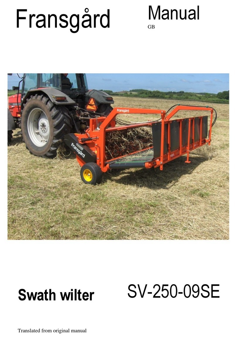
Figure 1: Remember to
tighten bolts
Figure 2: Remember to tighten
chains

3
Take note of two different sizes of hydraulic hose and take them through brackets on three-point suspension
(42505) and intermediate frame (42407).
Assemble protective bracket (42454) and protective mounting (42458) with bolts and nut (740205125,
74020010, 740080145), then mounting (42488), mounting (42489) and mounting (42458) with bolts (15558)
and split pin (1220040).
When mounting is complete, fit on machine's left gearbox with bolt (740210400), sprocket (740770030) and
washer (42457).
Keep protective bracket (42454) in place by means of mounting (42456), bolt (42455) and split pin (1220040).
Assemble protective bracket (42493) and protective mounting (42494) with bolt (740210405) and lock nut
(740420012). Then fit complete mounting on machine's right gearbox with bolt (740210400), sprocket
(740770030) and washer (42457). Keep protective bracket in place by means of retainer (42492) and split pin
(1220040).
Mount the PTO shaft. Mount the fitting with tines.
The machine is set in working position 3. at the factory.
See also the mounting/spare parts drawings on the following pages.
WORKING POSITION
The TI-6000 combirake has two work settings for the three-point suspension:
A: Top-link attachment in fixed position.
B: Top-link attachment in floating position.
When driving on slopes and hillsides etc., it is best to have the three-point suspension in the fixed position
(A :).
The TI-6000 combirake has four different working positions:
POS.1: RAKING INTO SIDE SWATHS
When raking to the side, the rotors rotate in the same
direction (by adjusting the lever on reversing gear 42509)
as shown in figure 5. The rotors are engaged in the
reversing gear in such a way that the pick-up springs
cannot touch,
Figure 3: Tight position (A).
Figure 4: Floading position (B).
Figure 5: Position 1 & 2 –Reverse gear (42509).

4
Figure 6: Position 1 - Positioned at an angle behind the tractor
The machine always runs obliquely behind the tractor (adjust bolt 42452). The wheels are
adjusted so that they run parallel to the direction of travel as illustrated in Figure 6. The right
guard bar must be mounted and the left guard bracket must be mounted and adjusted in the
middle hole of the bracket (42456). The catch arm is set with bracket (42489) to the desired
position.
A
B
C
Figure 7: Three different options for cam guide.
The cam guide (42440) on both rotors has three
adjustment options; A, B & C. For position 1, both
curve guides are set in position A r i position A, as
illustrated figure 7.
Figure 8: Placing the nylon wheel.
The rake arms run in the cam guide, which ensures
that the pick-up tines are lifted and lowered. It is
important that the nylon wheels are positioned
correctly in the cam guide so that they are dragged
after the direction of rotation, which is shown in
figure 8.

5
POS. 2: RAKING INTO 2 SWATHS
Figure 9: Position 2 –Placed behind the tractor.
When raking into double swaths, adjust the machine to the maximum working width (cylinder 42451), and
have the rake running straight behind the tractor (adjust bolt 42452). –see figure 9 –if necessary.
The right-hand protective bracket should have been fitted, while the left-hand protective bracket should be
fitted and adjust in the outermost hole on the mounting (42456).
The rotors run in the same direction of rotation (handle on turning gear 42509) as illustrated in figure 5, and
the tine arms run in the cam guide.
Both cam guides (42440) are set in position B, as illustrated in figure 7.
Figure 10: Adjusting Wheel height.
The wheel height is adjusted by disconnecting the
safety split (1210060) and rivet (41431). Hereby
there are 5 adjustment possibilities on fittings
(42471).
Figur 11: Setting the driving direction.
The wheels can be rotated so that they always run
parallel to the driving direction. Safe splits (1210060)
removed, rivet (41431) lifted, where the wheel
bracket are rotating.

6
POSITION 3: RAKING INTO CENTRAL SWATHS
Figur 12: Position 3 –Placing behind the tractor.
When raking into central swaths, the machine always
run straight behind the tractor (adjust bolt 42452). The
rotors rotate in opposite directions (lever on reversing
gear 42509), as shown in figure 13.
The Rotors are engaged in the reversing gear in
such a way that the pick-up springs cannot touch,,
while the rake arms run in the cam guide.
Adjust the wheels so in the fact that they run parallel to
the driving direction.
The right-hand protective should have been fitted,
while the left-hand protective bracket should be fitted
and adjusted in the outermost hole on the mounting
(42456).
Remove the catch arm.
Left cam guide (42440) is set in position C, and the
right cam guide is set in position B, according figure 7.
Bracket for the tine arms (55513) on the left rotor is
turned 180o . Split (42479) is removed as shown in
figure 15. The fitting for the rake arm is retracted and
turned, subsequent fittings for rake arms are retracted
and reversed, so there is space to mount the previous
bracket in the cam guide –see figure 16 if necessary.
The reverse has to be in the highest level of the cam
guide.
The rake arms has to be turned in correct working
position (see figure 15).
Figure 13: Position 3 & 4 –Reverse gear (42509).
Figure 14: Split (42479) removes.
1
Figure 15: Turn the rakearms to correct working
position.
2
3
Figure 16: Bracket for the tine arms (55513)
pulled backwords and turne 180o.

7
POS. 4: SPREADING
Figure 17: Position 4 - Placing behind the tractor.
When spreading, the machine runs straight behind the tractor (adjust bolt 42452). The rotors rotate in
opposite direction (lever on reversing gear 42509), as shown on figure 13.
The rotor is engaged in the reversing gear in such a way the pick-up springs cannot touch each
other. Put the rake arms in the fixed position (see illustration pos.4), tilt machine forward (adjust cylinder
42411) and adjust wheel height.
The protective brackets should have been fitted and the catch arm can be turned up if necessary.
The working width is infinitely variable and can be adjusted to suit the nature of the crop by cylinder
(42451).
Figure 18: The rake arms are mounted in fixed
working position.
Figure 19: Tilt the machine by a cylinder
cylinder (42411).

8
TRANSPORT POSITION
Change-over from working position to transport position is as follows:
Telescope small cylinder (42411) completely.
Telescope large cylinder (42451) completely.
Remove bolt (42452) and swing the machine back until locking pawl (42439) engages., as illustrated on
figure 20.
Remove retainer (42492), turn right-hand protective bracket in behind the tractor.
Replace retainer (42492) so in the fact that safety bracket is locked in position. Turn left-hand
protective bracket in behind tractor and turn catch arm up. Turn mounting (42456) back and fit
on protective bracket to lock in position.
Fit rake arms as shown in illustration on figure 21.
Remove the catch arm.
.
Figure 20: Lock ratchet (42439)
engages, so the machine is
locked in transport position.
Figure 21: The machine is switched to transport
position.

9
ORDERING SPARE PARTS
The spare part order must contain the following information:
1. Machine type.
2. Spare part number and description-possibly dimensions and number of parts.
LUBRICATION AND MAINTENANCE
Lubricate PTO shaft after every 10 hours of operation, and lubricate the indicated lubrication points as and
when required.
Retighten bolts.
The gearbox is filled with 0.8 liters of SAE 90 gear oil. It should be checked daily and filled up if necessary.


This manual suits for next models
1
Table of contents
Other Fransgard Farm Equipment manuals

Fransgard
Fransgard TI-5000 User manual

Fransgard
Fransgard SV-2500SE User manual

Fransgard
Fransgard GT-250 HY User manual

Fransgard
Fransgard Swath Wilter SV-2500 User manual

Fransgard
Fransgard SR-3200T User manual

Fransgard
Fransgard SV-250-09SE User manual

Fransgard
Fransgard GT-300AUS User manual

Fransgard
Fransgard SK-950 User manual

Fransgard
Fransgard DM-3250 User manual

Fransgard
Fransgard FKR-150 User manual