Rabe Super Albatros 140 RMW+ User manual

www.rabe-gb.de
OPERATING INSTRUCTIONS EN
(TRANSLATION OF THE ORIGINAL)
Serial no.
Attachment-reversible plough
Super Albatros 140 RMW+, Series 2
Super Albatros 160 RMW+, Series 2


- 3 -
BRIEF INSTRUCTIONS SUPER ALBATROS 140 MW; SERIES 2
9901.00.34DE00; 02.2017 6XEMHFWWRWHFKQLFDOPRGL¿FDWLRQV
Quick guide for experienced operators, always observe the detailed operating
instructions as well.
BRIEF INSTRUCTIONS
1 PREPARING THE TRACTOR
ŹCalculate required ballast for the tractor, then
attach ballast.
ŹCheck that the air pressure in the tractor's tyres
is correct and equal.
ŹCheck the output and lifting capacity of the rear
power lift on the tractor in relation to the plough
version.
ŹCheck the permissible axle load for the tractor.
ŹCheck that tractor’s and implement’s
connection categories are the same.
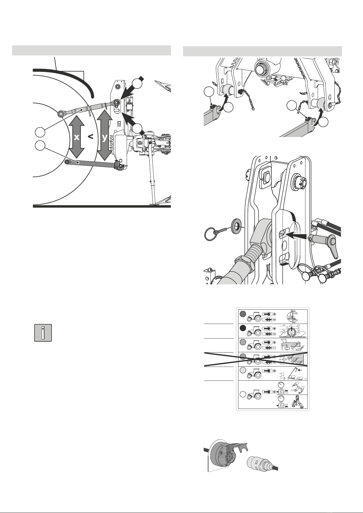
ŹSet the bottom links to the same height.
ŹLimit the bottom links to a low lateral ...
... tolerance with the side locks when raised
and adjust them so that they ...
... move freely when lowered.
ŹSet the tractor hydraulics to traction control.
ŹCheck the bottom link’s lifting height.
Minimum lifting height = 85 cm
BRIEF INSTRUCTIONS
TABLE OF CONTENTS FOR THE BRIEF INSTRUCTIONS
1 Preparing the tractor ......................................................... 3
2 Coupling the implement.................................................... 4
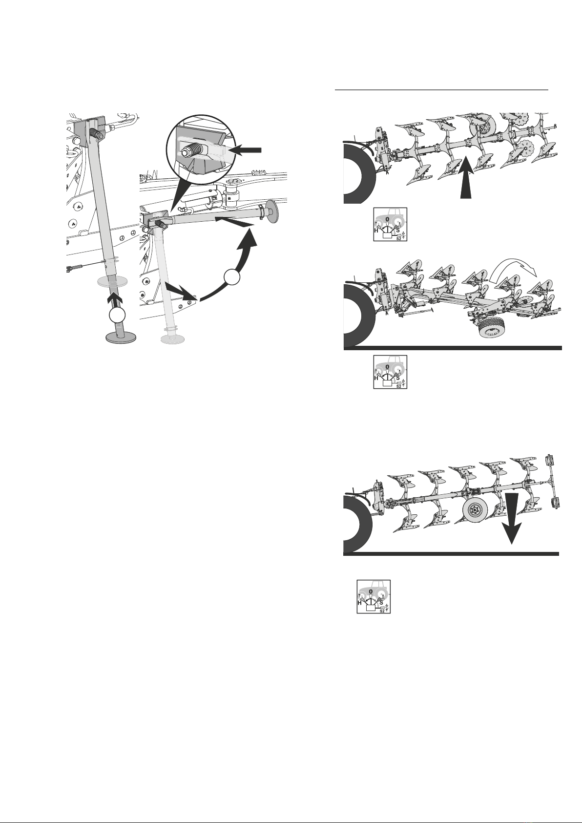
3 Folding up the parking support........................................ 5
4 Moving the plough into the transport position............... 5
4.1 Turning the plough onto the right-hand side.............. 5
4.2 Turning the combination wheel into the transport
position ...................................................................... 6
4.3 Lifting the ploughs with depth guide wheel into the
transport position....................................................... 7
5 Travelling by road.............................................................. 7
6 Moving the plough with combination wheel into the
working position................................................................ 8
7 Moving the plough with depth control wheel into the
working position................................................................ 9
8 Removing the lighting....................................................... 9
9 Working values: Working speed / working depth........... 9
10 Adjusting the traction point............................................ 10
10.1 Plough with turnbuckle ............................................ 10
10.2 Plough with hydraulic frame slewing ....................... 10
11 $GMXVWLQJWKH¿UVWERG\ZRUNLQJZLGWK......................... 11
11.1 Plough with adjusting spindle .................................. 11
11.2 Ploughs with hydraulic cylinder ............................... 11
12 Adjusting the working depth .......................................... 12
12.1 Preparation.............................................................. 12
12.2 Depth adjustment, depth control wheel PS 5 .......... 12
12.3 Depth adjustment, depth control wheel PS 30
and combination wheel D 30 ................................... 12
12.4 Depth adjustment, RJR wheel................................. 13
13 Aligning the plough parallel to the ground ................... 13
14 Adjusting the incline ....................................................... 14
15 Installing the lighting...................................................... 14
16 Adjusting the working width........................................... 15
17 Adjusting the track of the contact or combination
wheel................................................................................. 15

- 4 -
BRIEF INSTRUCTIONS SUPER ALBATROS 140 MW; SERIES 2
9901.00.34DE00; 02.2017
Subject to technical modifications
Coupling
a
a
1.
1.
ŹCouple and lock the bottom link (a).
ŹCouple the top link.
Red
9998.02.65
Black
Blue
Green
Yellow
White
ŹConnect the hydraulic line.
ŹConnect the lighting cable.
2 COUPLING THE IMPLEMENT
Notes on coupling
A
B
2
1
• The bottom link (1) must slope downwards
slightly towards the implement.
• Attach the top link (2) so that it slopes upwards
towards the working implement.
x < Y
• The incline can be changed by inserting the top
link stock in position A or B.
• Insert the top link into the elongated hole.
%HQH¿WV
- Quicker soil penetration
- Safer bottom guidance
- Load reduction on the plough hydraulics
NOTE
Insert the top link into the hole if the soil is
heavy.

- 5 -
BRIEF INSTRUCTIONS SUPER ALBATROS 140 MW; SERIES 2
9901.00.34DE00; 02.2017 6XEMHFWWRWHFKQLFDOPRGL¿FDWLRQV
3 FOLDING UP THE
PARKING SUPPORT
Ź1.) Lift the plough using the three-point power
lift until the parking support is free.
3.
2.
Ź2.) Insert the parking support and pin it to
the shortest position.
Ź3.) Fold up and lock the parking support..
4 MOVING THE PLOUGH INTO
THE TRANSPORT POSITION
4.1 Turning the plough onto the right-hand side
Ź1.) Lift the plough.
Minimum lifting height = 85 cm
Ź2.) Actuate the control device.
Rotate the plough completely
to the right-hand side.
For hydraulic frame slewing,
actuate the control device until
hydraulic frame slewing is pivoted
out completely again.
Once the plough is in the end position.
ŹRelease the control device.
Ź Lower the plough.

- 6 -
BRIEF INSTRUCTIONS SUPER ALBATROS 140 MW; SERIES 2
9901.00.34DE00; 02.2017
Subject to technical modifications
Working position
Ź1.) Lift the plough.
Minimum lifting height = 85 cm
Ź2.) Turn the plough slowly until the
central lock engages.
Transport position
Ź3.)
Lower the plough until the
combination wheel meets the ground.
2.
1.
3.
ŹUncouple the top link.
4.2 Turning the combination wheel into
the transport position
A = working position for the locking pin
T = transport position
...im Einsatz
...au travail
...working position
9998.02.78
...im Transport
...position transport
...transpoert position
...im Einsatz
...au travail
...working position
9998.02.78
...im Transport
...position transport
...transpoert position
A
T
3.
4.
2.
5.
1.
ŹPin the combination wheel into the transport
position.
...im Einsatz
...au travail
...working position
9998.02.78
...im Transport
...position transpor t
...transpoer t position
...im Einsatz
...au travail
...working position
9998.02.78
...im Transport
...position transpor t
...transpoer t position
1.
2.
3.
T
A
4.
5.
ŹPin the wheel console into the transport position.
V
E
1.
ŹLock the central lock.
V = Locked = transport position,
turning locked
E = Unlocked = working position,
turning possible

- 7 -
BRIEF INSTRUCTIONS SUPER ALBATROS 140 MW; SERIES 2
9901.00.34DE00; 02.2017 6XEMHFWWRWHFKQLFDOPRGL¿FDWLRQV
4.3 Lifting the ploughs with depth guide wheel
into the transport position
Ź1.) Lift the plough out of the working
position and into the transport
position.
Ź2.) Lock the lateral movement of the tractor’s
bottom link (tractor operating instructions).
Ź3.) Lock the tractor’s control devices (tractor
operating instructions).
5 TRAVELLING BY ROAD
Driving instructions
• Adapt your driving speed to conditions on the
road or track.
• Max. speed = 25 kph
• Max. speed when transporting on a
combination wheel = 25 km/h
Check before moving off
• The parking support is folded in and secured.
• All hydraulic control devices are locked (tractor
operating instructions).
• The bottom link lateral lock is applied (tractor
operating instructions).
• The lighting is installed.
• Indicators, tail lights and reversing lights are
working.
• The pick-up arm is folded into the transport
position (pick-up arm operating instructions).

- 8 -
BRIEF INSTRUCTIONS SUPER ALBATROS 140 MW; SERIES 2
9901.00.34DE00; 02.2017
Subject to technical modifications
Ź2.) Actuate the control device.
Rotate the plough completely
to the right-hand side.
For hydraulic frame slewing,
actuate the control device until
hydraulic frame slewing is pivoted
out completely again.
Working position
...im Einsatz
...au travail
...working position
9998.02.78
...im Transport
...position transport
...transpoert position
...im Einsatz
...au travail
...working position
9998.02.78
...im Transport
...position transport
...transpoert position
2.4.
1.
5.
3.
T
A
ŹTurn the combination wheel into the working position.
T = transport position / A = working position
...im Einsatz
...au travail
...working position
9998.02.78
...im Transport
...position transport
...transpoert position
...im Einsatz
...au travail
...working position
9998.02.78
...im Transport
...position transport
...transpoert position
1.
5.
2.
3.
4.
TA
ŹPivot the wheel console into the working position.
T = transport position / A = working position
6 MOVING THE PLOUGH WITH
COMBINATION WHEEL INTO
THE WORKING POSITION
1.
2.
ŹCouple the top link.
V
E
1.
ŹUnlock the central lock.
V = Locked = Transport position
Rotation locked.
E = Unlocked = Working position
Rotation possible
Transport position
Ź1.) Lift the plough.
Minimum lifting height = 85 cm

- 9 -
BRIEF INSTRUCTIONS SUPER ALBATROS 140 MW; SERIES 2
9901.00.34DE00; 02.2017 6XEMHFWWRWHFKQLFDOPRGL¿FDWLRQV
7 MOVING THE PLOUGH WITH
DEPTH CONTROL WHEEL INTO
THE WORKING POSITION
ŹLower the plough from the transport
position into the working position.
8 REMOVING THE LIGHTING
1. 2.
3.
4.
5.
ŹRemove the lighting bar.
To store the locking pin:
1
2
3
Ź6FUHZWKHVWDUJULSVFUHZ1) tight.
Ź,QVHUWWKHORFNLQJSLQ2) into the
frame tube and secure with the
spring cotter (3).
9 WORKING VALUES:
WORKING SPEED /
WORKING DEPTH
Working speed
Working speed = 4 km/h - 10 km/h
7KHZRUNLQJVSHHGGHSHQGVRQWKHIROORZLQJ
• The composition of the ground
• Plant cover
• The working width
• The working depth
• Wear and tear
Solid sheet body working depth
Body designation
Maximum working
depth
approx. cm
BP-351 O 40
BP-322 P 38
BP-320 W 30
BP-341 W 35
BP-351 W 35
BP-365 P 30
Slatted body working depth
Body designation
Maximum working
depth
approx. cm
BP-331 WS 30
BP-322 PS 38
BPC-323 PS 38
BP-355 RS 40
BP-351 WS 35

- 10 -
BRIEF INSTRUCTIONS SUPER ALBATROS 140 MW; SERIES 2
9901.00.34DE00; 02.2017
Subject to technical modifications
10 ADJUSTING THE
TRACTION POINT
10.1 Plough with turnbuckle
Tools
Spanner with a width of 55 mm
(supplied)
Adjustment instructions
2 1
21
1) Tractor moves towards ploughed soil
= shorten the turnbuckle.
2) Tractor moves towards unploughed soil
= extend the turnbuckle.
10.2 Plough with hydraulic frame slewing
Tools
• Hook spanner with hexagon for a width of
13 mm (supplied)
• Allen key with a width of 10 mm
Adjustment instructions
2 1
21
1) Tractor moves towards ploughed soil
= shorten the cylinder path with a stop.
2) Tractor moves towards unploughed soil
= extend the cylinder path with a stop.

- 11 -
BRIEF INSTRUCTIONS SUPER ALBATROS 140 MW; SERIES 2
9901.00.34DE00; 02.2017 6XEMHFWWRWHFKQLFDOPRGL¿FDWLRQV
11.2 Ploughs with hydraulic cylinder
NOTE
When adjusting hydraulically, only adjust
the traction point when the implement is
at a standstill and lowered.
D´
D
1.
1.
Ź1.) Actuate the control device for the
tractor hydraulics until the
determined gap (DRQWKH¿UVW
body (D´) is adjusted.
=
=
Retract the adjusting spindle.
,QFUHDVH¿UVWERG\ZRUNLQJZLGWK(D´) .
=
=
Extend the adjusting spindle.
'HFUHDVH¿UVWERG\ZRUNLQJZLGWK(D´) .
11ADJUSTING THE FIRST-
BODY WORKING WIDTH
11.1 Plough with adjusting spindle
D´
D
1.
1.
Ź1.) Rotate the adjustment spindle and re-adjust
the determined gap (DRQWKH¿UVWERG\'
=
=
Rotate adjusting spindle to the right.
,QFUHDVH¿UVWERG\ZRUNLQJZLGWK(D´)
=
=
Rotate adjusting spindle to the left.
'HFUHDVH¿UVWERG\ZRUNLQJZLGWK(D´)

- 12 -
BRIEF INSTRUCTIONS SUPER ALBATROS 140 MW; SERIES 2
9901.00.34DE00; 02.2017
Subject to technical modifications
12 ADJUSTING THE
WORKING DEPTH
12.1 Preparation
ŹPlough for a few metres with the plough in the
home position.
ŹMeasure the working depth.
ŹLift the plough slightly if adjustment is required.
12.2 Depth adjustment, depth control wheel PS 5
a
ŹAdjust the working depth by rotating the
adjustment spindle.
The pawl (a) secures the rotating spindle
to prevent it rotating while ploughing.
= Rotate adjusting spindle to the left
= Increase working depth
= Rotate adjusting spindle to the right
= Decrease working depth
12.3 Depth adjustment, depth control wheel PS 30
and combination wheel D 30
Adjusting the working depth mechanically
a
ŹAdjust the working depth by rotating the
adjustment spindle. a = adjustment marking
= Rotate adjusting spindle to the right
= Increase working depth
= Rotate adjusting spindle to the left
= Decrease working depth
Adjusting the working depth hydraulically
a
ŹActuate the tractor hydraulics for the
depth adjustment hydraulic cylinder
until the required working depth has
been reached.
= Retract adjustment cylinder
= Increase working depth
= Extend adjustment cylinder
= Decrease working depth

- 13 -
BRIEF INSTRUCTIONS SUPER ALBATROS 140 MW; SERIES 2
9901.00.34DE00; 02.2017 6XEMHFWWRWHFKQLFDOPRGL¿FDWLRQV
13ALIGNING THE PLOUGH
PARALLEL TO THE GROUND
Preparation
ŹLower the plough onto the contact or
combination wheel.
ŹPlough for another metre.
ŹCheck that the plough is parallel to the ground
(visual inspection).
Adjustment
2
1
a
Position the plough parallel to the ground,
to do this:
ŹAdjust the bottom link height (1).
ŹSet the top link (2) shorter or longer.
7KHWRSOLQNVKRXOG
- be slightly inclined towards the tractor.
- make contact slightly forward on level ground
and when ploughing in an elongated hole (a).
12.4 Depth adjustment, RJR wheel
1
1
ŹAdjust the working depth by rotating the limit
stops (1).
Adjust both limit stops evenly.
= Rotate to the right limit stop
= Increase working depth
= Rotate adjusting spindle to the left
= Decrease working depth

- 14 -
BRIEF INSTRUCTIONS SUPER ALBATROS 140 MW; SERIES 2
9901.00.34DE00; 02.2017
Subject to technical modifications
14 INSTALLING THE LIGHTING
Remove the locking pin from storage:
1
3
2
Ź 8QVFUHZWKHVWDUJULSVFUHZ
Ź 5HPRYHWKHVSULQJFRWWHU
Ź5HPRYHWKHORFNLQJSLQIURP
the frame tube.
5.
4.
3.
2.
1.
Ź1.) Insert the lighting bar.
15 ADJUSTING THE INCLINE
Preparation
ŹPlough for a few metres with the plough in the
home position.
ŹTractor and plough in working position, tractor
wheel in furrow.
ŹCheck the incline from the legs to the
unploughed soil (visual inspection).
Adjustment
90°
90
°
90°
1
2
ŹRotate spindles (1) or (2) until the correct in-
cline is reached.
Spindle 1 = Incline adjustment for the right-
hand bodies
Spindle 2 = Incline adjustment for the left-
hand bodies

- 15 -
BRIEF INSTRUCTIONS SUPER ALBATROS 140 MW; SERIES 2
9901.00.34DE00; 02.2017 6XEMHFWWRWHFKQLFDOPRGL¿FDWLRQV
16 ADJUSTING
THE WORKING WIDTH
1
2
3
B
1
2
3
3.
3.
1.
1
3
2.
Ź1.) Unscrew the pivot bolt (AF 36 mm).
Ź2.) Remove the fastening bolt (AF 36 mm).
Ź3.) Turn the console until the hole of the
desired working width aligns with the frame
hole.
Position Working width
1* 44 cm (17,5“)
250 cm (19,7“)
356 cm (22“)
* Factory setting
Ź4.) Insert fastening bolt with washer in the
appropriate hole.
Ź5.) Tighten all fastening and pivot bolts with the
correct torque.
Torques
Size :LGWKDFURVVÀDWV
Nm lb-ft
M24 710 524 36
NOTE
• Tighten the expansion screws only
ZLWKWKHVSHFL¿HGWRUTXH
• After adjusting the working width,
adjust the track of the contact or
combination wheel.
17 ADJUSTING THE TRACK
OF THE CONTACT OR
COMBINATION WHEEL
1
1
2
2
3
3
4
4
9998.02.79
12
3
4
X
2.
5.
3.
4.
a
1.
Ź1.) Remove the fastening bolt (AF 30 mm).
Ź2.) Unscrew the pivot bolt (AF 30 mm).
Ź3.) Turn the wheel holder until the hole (a) of
the adjusted working width aligns with the
frame hole.
Position Working width
1* 44 cm (17,5“)
2 50 cm (19,7“)
3 56 cm (22“)
X hole not used
Ź4.) Insert fastening bolt with washer in the
appropriate hole.
Ź5.) Tighten all fastening bolts to the correct
torque.
Torques
Size Quality grade 8.8 :LGWKDFURVVÀDWV
Nm lb-ft
M20 464 342 30


- 17 -
Any duplication of this instruction manual, whether in full or in part, is prohibited without written approval from Grégoire-Besson, regardless of the country, format or medium.
9901.00.34DE00; 02.2017 6XEMHFWWRWHFKQLFDOPRGL¿FDWLRQV
TABLE OF CONTENTS SUPER ALBATROS 140 MW; SERIES 2
INTRODUCTION ......................................21
1 Notes on the operating instructions .............22
2 Symbol descriptions.......................................22
3 Target audience of these operating instruc-
tions .................................................................22
4 Intended use....................................................22
5 For your safety ................................................23
5.1 General safety information .............................. 23
5.2 Who may operate the implement? .................. 23
5.2.1. 'H¿QLWLRQRISHUVRQQHOTXDOL¿FDWLRQV ........23
5.3 Workplace ....................................................... 23
5.4 Safety instructions - general usage................. 23
5.5 Safety instructions - loading ............................ 24
5.6 Ballast calculation ........................................... 25
5.7 Safety instructions - coupling/uncoupling........ 25
5.8 Hydraulic safety instructions ........................... 25
5.9 Pressure tank safety instructions .............. 25
5.10 Safety instructions - oils and greases ............. 26
5.11 Safety instructions - Travelling by road / transport
26
5.12 6DIHW\LQVWUXFWLRQV¿HOGXVH .......................... 26
5.13 Safety instructions - care, maintenance and
repair ............................................................... 27
5.14 Meanings of the safety symbols...................... 28
DESCRIPTION.........................................29
6 Scope of delivery ............................................29
6.1 Basic equipment.............................................. 29
6.2 6.2 ......................................Additional equipment
29
7 Description of the implement ........................30
7.1 Description of the components........................ 31
7.2 Description of the components on the plough
body ................................................................ 31
8 Description of the components .....................33
8.1 Tower for Super Albatros ................................ 33
8.2 Rotation cylinder ............................................. 34
8.3 Central lock ..................................................... 34
8.4 Adjustment centre ........................................... 34
8.4.1. First-body working width adjustment ........34
8.4.2. Traction point adjustment .........................34
8.4.3. Frame swivel cylinder ..............................35
8.4.4. Working width adjustment ........................35
8.5 Depth control with depth control wheel or combi-
nation wheel .................................................... 35
8.6 Bodies ............................................................. 36
8.7 Tines ............................................................... 36
8.8 Add-on coulter................................................. 36
8.9 Trash board .................................................... 36
8.10 Round rod skimmer......................................... 36
8.11 Vari-Fix skimmer ............................................. 36
8.12 Vari Heavy Duty (VHD) skimmer..................... 37
8.13 Disc coulter .................................................... 37
8.14 Plough body stone protection system ............. 37
8.15 Subsoiler stone protection system .................. 37
8.16 Leg reinforcements ......................................... 38
8.17 Parking support ............................................... 38
8.18 Frame set ........................................................ 38
8.19 Lighting unit..................................................... 38
9 Technical data .................................................39
9.1 Technical data for solid sheet body................. 40
9.2 Technical data for slatted body ....................... 40
9.3 Technical data for pressure tank for tower sus-
pension............................................................ 40
9.4 Individual weights of the additional equipment 41
9.5 Required hydraulic connection........................ 41
9.6 Required power connection ............................ 41
OPERATING INSTRUCTIONS

- 18 -
Any duplication of this instruction manual, whether in full or in part, is prohibited without written approval from Grégoire-Besson, regardless of the country, format or medium.
9901.00.34DE00; 02.2017
Subject to technical modifications
TABLE OF CONTENTS SUPER ALBATROS 140 MW; SERIES 2
9.7 Maximum permissible dimensions and weights
for transport by road........................................ 41
9.8 Explanation of the type designation ................ 42
9.9 Type plate, mark ....................................... 42
10 Loading ............................................................42
OPERATION............................................43
11 Preparing the tractor ...................................... 43
11.1 Checking requirements for the tractor............. 43
11.2 Checking the tractor’s air pressure ................. 43
11.3 Checking the track width ................................. 43
11.4 Ballast weight .................................................. 43
12 Coupling the implement................................. 44
12.1 Notes on coupling ........................................... 44
12.2 Bottom link connection .................................... 44
12.2.1. Connection categories..............................44
12.2.2. Ball bush and guide cone for bottom link
bolt............................................................44
12.3 Couple the bottom links................................... 45
12.4 Couple the top link .......................................... 45
12.5 Couple the top link .......................................... 46
12.6 Connect the hydraulic lines ............................. 46
12.6.1. Required hydraulic connections ...............47
12.6.2. Connect the hydraulic lines ......................47
12.7 Connecting the lighting cable .......................... 47
13 Sliding in and folding up the parking support .
48
14 Carrying out the turning test ......................... 49
15 Adjusting the working width.......................... 50
16 Adjusting the track of the contact or combina-
tion wheel ........................................................51
17 Preparing the machine, pre-adjustments ....53
17.1 Information on the model ................................ 53
17.2 Required preparations..................................... 53
17.3 General adjustment instructions...................... 53
17.4 Pre-adjusting the traction point ...................... 54
17.4.1. Adjustment instructions ............................54
17.4.2. Ploughs with turnbuckle...........................54
17.4.3. Ploughs with hydraulic frame slewing.......55
17.5 $GMXVWLQJWKH¿UVWERG\ZRUNLQJZLGWK............. 56
17.5.1. Adjusting the ploughs with adjusting spindle
56
17.5.2. Adjusting the ploughs with hydraulic cylin-
ders...........................................................56
18 Moving the plough into the transport
position ............................................................ 57
18.1 Turning the plough onto the right-hand side ... 57
18.2 Turn the ploughs with combination wheel into the
transport position............................................. 57
18.2.1. Turning the combination wheel into
the transport position ................................58
18.2.2. Locking the central lock ............................59
18.2.3. Turning the plough into the transport position
59
18.2.4. Uncoupling the top link .............................59
18.3 Lifting the ploughs with depth guide wheel into
the transport position....................................... 60
19 Travelling by road...........................................60
19.1 Preparations for travelling by road .................. 60
19.2 Driving instructions.......................................... 60
19.3 Check before moving off ................................ 61
20 Moving the plough from the transport position
to the working position ..................................61
20.1 Removing the lighting...................................... 61
20.2 Turn the plough with combination wheel into the
working position .............................................. 62
20.2.1. Coupling the top link .................................62
20.2.2. Unlocking the central lock.........................62
20.2.3. Turning the plough onto the right-hand
side ...........................................................62
20.2.4. Turning the combination wheel into the
working position........................................63
20.3 Lowering the plough with depth control wheel
into the working position.................................. 64
20.4 Moving the subsoiler into the working position 64
21 Working information.......................................65
21.1 Safety during operation ................................... 65
21.2 :RUNLQJYDOXHV:RUNLQJVSHHGZRUNLQJ
depth ............................................................... 65
21.3 Working information ........................................ 66
21.4 Driving instructions - turning on headlands ..... 66
21.5 Operational safety on a hillside ....................... 66
22 Adjustments after ploughing......................... 67
22.1 Adjusting the working depth ............................ 67
22.1.1. Adjustment instructions ............................67
22.1.2. Preparation ...............................................67
22.1.3. Depth adjustment, depth control wheel
PS 5..........................................................67
22.1.4. Depth adjustment, depth control wheel
PS 30 and combination wheel D 30 .........67
22.1.5. Depth adjustment, RJR wheel ..................68
22.2 Aligning the plough parallel to the ground....... 68
22.3 Adjusting the incline ........................................ 69

- 19 -
Any duplication of this instruction manual, whether in full or in part, is prohibited without written approval from Grégoire-Besson, regardless of the country, format or medium.
9901.00.34DE00; 02.2017 6XEMHFWWRWHFKQLFDOPRGL¿FDWLRQV
TABLE OF CONTENTS SUPER ALBATROS 140 MW; SERIES 2
23 Adjustments during operation.......................69
23.1 Re-adjusting the traction point ....................... 69
23.1.1. Adjustment instructions ............................69
23.1.2. Re-adjusting the traction point - Plough
with turnbuckle..........................................69
23.1.3. Re-adjusting the traction point - Plough
with hydraulic frame slewing.....................70
23.2 5HDGMXVWLQJWKH¿UVWERG\ZRUNLQJZLGWK ....... 71
23.2.1. Adjusting the ploughs with adjusting
spindle ......................................................71
23.2.2. Adjusting the ploughs with hydraulic
cylinders ...................................................71
24 Adjusting the equipment................................ 72
24.1 Adjusting the trash boards .............................. 72
24.2 Adjusting the subsoiler .................................... 72
24.3 Adjusting the disc coulter ................................ 73
24.3.1. Adjusting the disc coulter's working depth 73
24.3.2. Adjusting the disc coulter side overlap .....73
24.3.3. Adjusting the stop of the swing arm
on the disc coulter ....................................74
24.4 Adjusting the round rod skimmer .................... 75
24.4.1. Adjusting the skimmer's working depth ....75
24.4.2. Adjusting the skimmer with round rod’s
side overlap ..............................................76
24.4.3. Adjusting the skimmer with round rod's
throwing angle ..........................................77
24.5 Adjusting the Vari-Fix skimmer ....................... 77
24.5.1. Adjusting the Vari-Fix skimmer’s working
depth ........................................................77
24.5.2. Vari-Fix skimmer - side overlap ................78
24.6 Adjusting the Vari Heavy Duty skimmers ........ 78
24.6.1. Vari Heavy Duty - adjusting the working
depth ........................................................78
24.6.2. Vari Heavy Duty skimmers - lateral
overlap......................................................79
25 After the work..................................................79
25.1 Required work ................................................. 79
25.2 Install the lighting ............................................ 79
26 Parking the implement ................................... 80
26.1 Prerequisite ..................................................... 80
26.2 Note the following when parking ..................... 80
26.3 Fold the parking support out and adjust the
length .............................................................. 80
26.4 Move the subsoiler into the storage position... 81
26.5 Parking the ploughs with combination wheel .. 82
26.5.1. Coupling the top link .................................82
26.5.2. Unlocking the central lock.........................82
26.5.3. Turning the plough onto the right-hand
side ...........................................................82
26.5.4. Turning the combination wheel into the stor-
age position ..............................................83
26.5.5. Parking the plough....................................83
26.6 Parking the ploughs with depth control wheel. 83
27 Uncoupling the implement............................. 84
27.1 Disconnecting hydraulic connections .............. 84
27.2 Disconnect lighting .......................................... 84
27.3 Uncoupling the top link.................................... 84
27.4 Uncoupling the bottom link.............................. 85
28 Storage information........................................85
29 Cleaning...........................................................85
29.1 Safety instructions........................................... 85
29.2 Cleaning information ....................................... 85
RECTIFY FAULTS ....................................87
30 Troubleshooting..............................................87
31 Replacing the shear bolt on plough bodies . 88
31.1 Replace the shear bolt .................................... 88
31.2 Replacing the shear bolt - reinforced, double
shear shaft ...................................................... 89
32 Replacing the Vari Heavy Duty (VHD) shear
bolt ...................................................................90
33 Replacing the shear bolt on the subsoiler ... 91
34 Adjust undercut .............................................. 92
35 Adjusting the spring force of the tower sus-
pension ............................................................95
MAINTENANCE .......................................96
36 Safety instructions - Maintenance and repair ..
96
36.1 Safety instructions - oils and greases ............. 96
36.2 Who may carry out maintenance? .................. 97
37 Test runs during or after maintenance .........97
38 Maintenance schedule....................................98
39 Lubricating points...........................................99
39.1 Lubricating adjusting spindles ....................... 100
40 Re-tighten all bolts........................................101
40.1 Key threaded connections............................. 101
41 Inspecting the hydraulics.............................102
41.1 ,GHQWL¿FDWLRQRQDK\GUDXOLFKRVH.................. 102
41.2 Check the hydraulic system .......................... 102
41.3 Pressure tank - checking and adjusting the gas
¿OOLQJSUHVVXUH ............................................... 102

- 20 -
Any duplication of this instruction manual, whether in full or in part, is prohibited without written approval from Grégoire-Besson, regardless of the country, format or medium.
9901.00.34DE00; 02.2017
Subject to technical modifications
TABLE OF CONTENTS SUPER ALBATROS 140 MW; SERIES 2
42 Replacing wear parts..................................103
42.1 Replacing mouldboards ................................ 103
42.2 Replace the stripes ....................................... 103
42.3 Replace the tine ............................................ 104
42.4 Replace the tines with reversible points........ 104
42.5 Replace the trash board................................ 105
42.6 Replace the subsoiler.................................... 105
42.7 Replace the skimmer tines and mouldboard. 106
42.8 Replace the disc coulter................................ 106
43 Replace the supporting wheel / combination
wheel .............................................................. 107
44 Replace the bulbs in the lighting.................108
INSTALLATION ..................................... 109
45 Installing the ball bush on bottom link bolts....
109
APPENDIX ............................................ 110
46 EU Declaration of Conformity...................... 110
47 Ballast calculation - combination of the tractor
and implement...............................................110
48 Position of the safety symbols and notice
labels..............................................................112
49 Tightening torques for metric bolts ............113
49.1 Tightening torques for metric bolts - standard
thread ............................................................ 113
49.2 7LJKWHQLQJWRUTXHVIRUPHWULFEROWV¿QHWKUHDG..
113
50 Notes on transport and lighting .................. 114
50.1 Notes on transport......................................... 114
50.2 ,PSOHPHQWLGHQWL¿FDWLRQOLJKWLQJ .................. 114
51 Electrical circuit diagram - lighting............. 115
52 Disposing of the implement......................... 116
This manual suits for next models
2
Table of contents
Other Rabe Farm Equipment manuals

Rabe
Rabe Digger HA User manual

Rabe
Rabe Kormoran PF 180 User manual

Rabe
Rabe KORMORAN PL V 180 User manual

Rabe
Rabe COMBIBIRD CB User manual

Rabe
Rabe KORMORAN PL V 180 User manual

Rabe
Rabe Aquila User manual

Rabe
Rabe KORMORAN SF 180 User manual

Rabe
Rabe Corvus PKE User manual

Rabe
Rabe Fitis 120 M User manual

Rabe
Rabe Packer CR User manual