Fransgard BF-7000 User manual

Manual
GB
Dual rotary rake
BF-7000

Fransgård Maskinfabrik A/S
Fredbjergvej 132
DK - 9640 Farsø
Phone : +45 98 63 21 22
www.fransgard.dk

Tabel of Contents
1. Introduction................................................................................................................................................................................ 1
2. The manual's target group ......................................................................................................................................................... 1
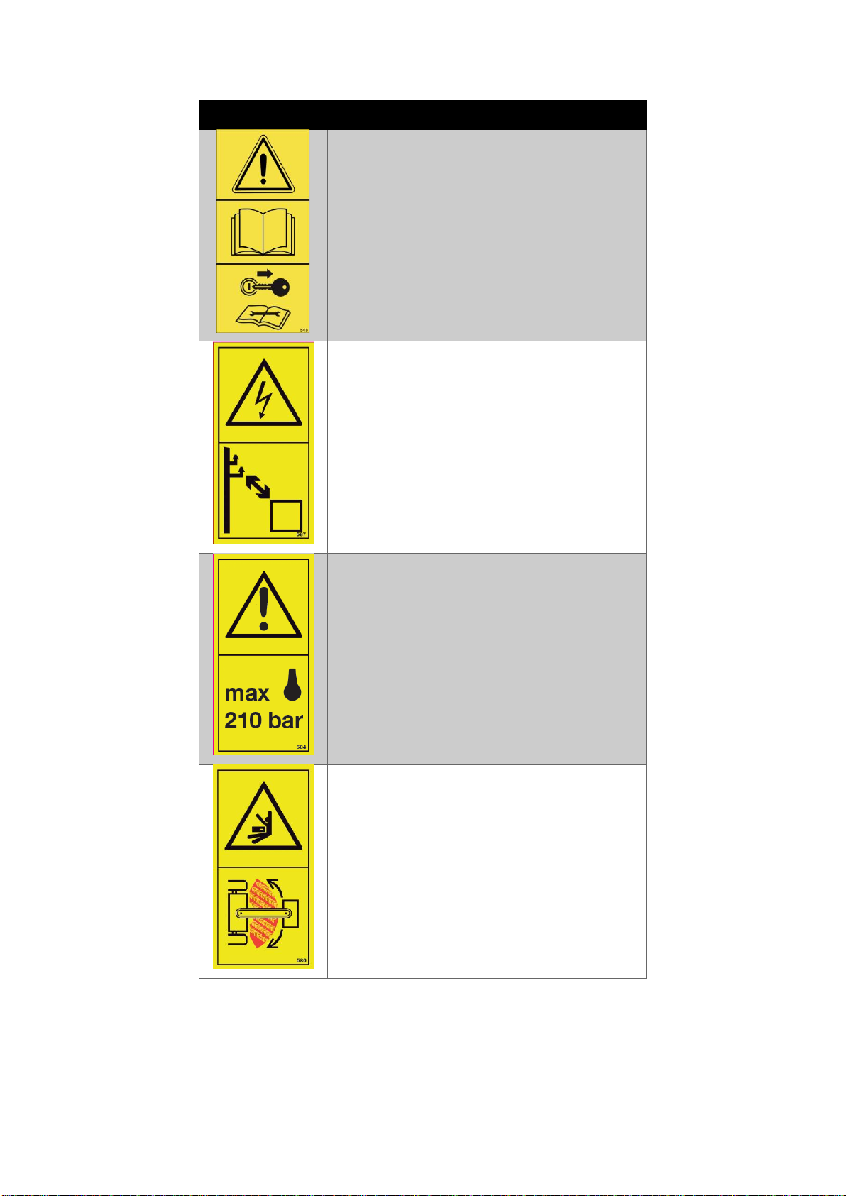
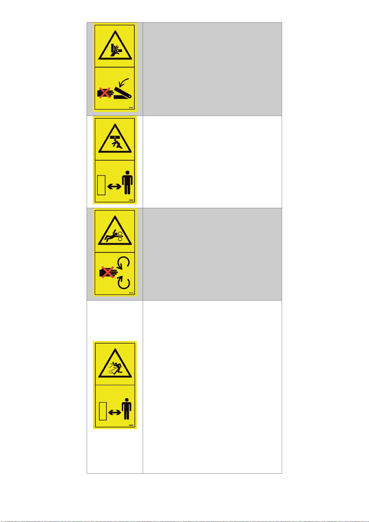
3. Symbols ...................................................................................................................................................................................... 2
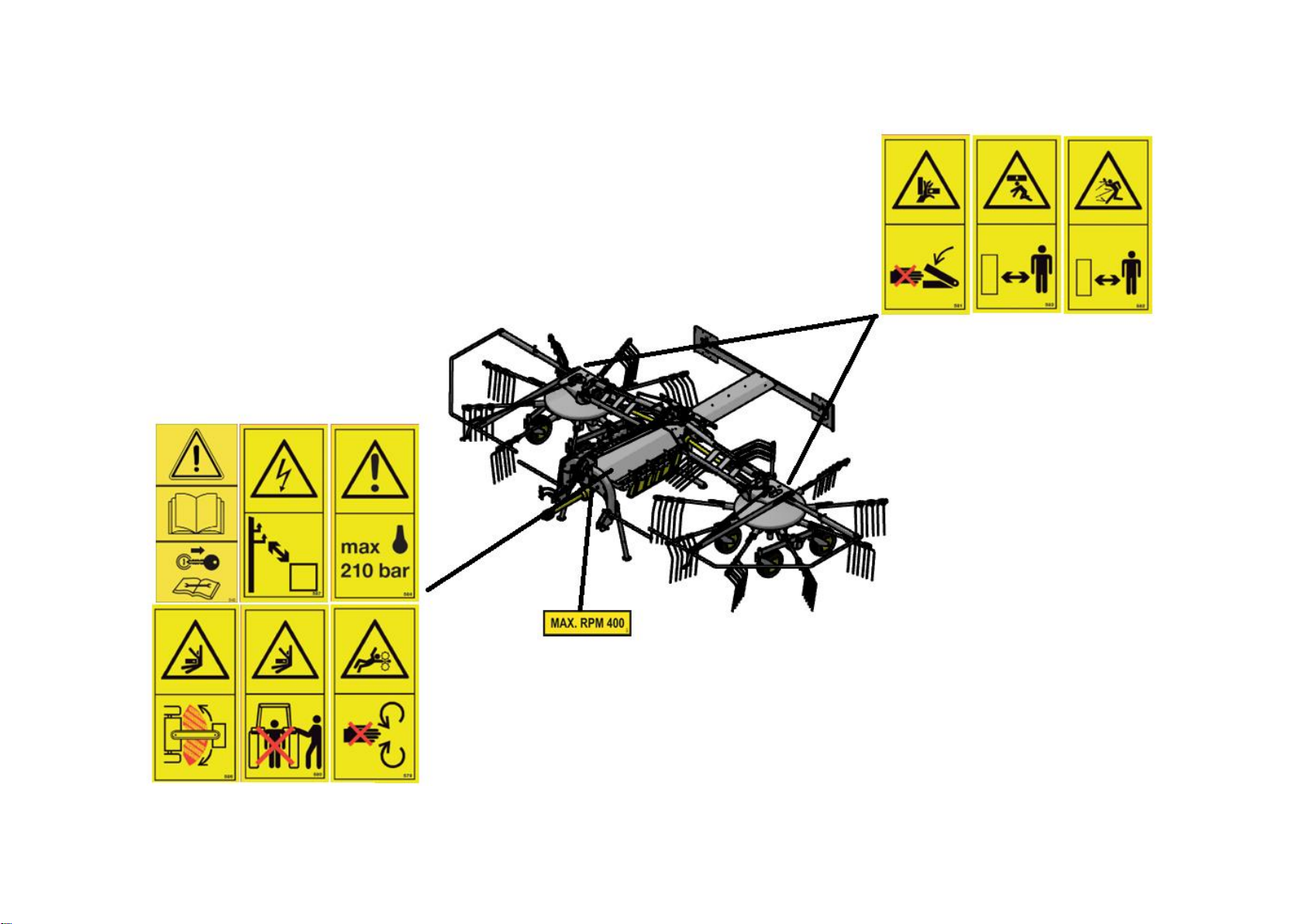
4. Placement of symbols................................................................................................................................................................. 5
5. Technical data ............................................................................................................................................................................ 6
6. Safety instructions ...................................................................................................................................................................... 7
6.1. Intended use....................................................................................................................................................................... 7
6.2. Who is allowed to drive the machine?............................................................................................................................... 7
6.3. The owner's responsibility.................................................................................................................................................. 7
6.4. Connecting the tool............................................................................................................................................................ 7
6.5. Disconnecting the tool ....................................................................................................................................................... 7
6.6. PTO axles ............................................................................................................................................................................ 8
6.7. Driving in the transport position ........................................................................................................................................ 8
6.8. Driving in operation............................................................................................................................................................ 8
6.9. Maintenance ...................................................................................................................................................................... 9
6.10. Hydraulics......................................................................................................................................................................... 9
7. Delivery and assembly of the machine..................................................................................................................................... 10
7.1. Delivery............................................................................................................................................................................. 10
7.2. The length of the PTO axle ............................................................................................................................................... 10
8. Preparing the machine for operation ....................................................................................................................................... 11
8.1. Connecting to the tractor................................................................................................................................................. 11
8.2. Connecting hydraulic hoses to the tractor ....................................................................................................................... 11
8.3. PTO axle connection......................................................................................................................................................... 11
8.4. Adjusting the inclination of the main frame..................................................................................................................... 12
8.5. Adjusting the rotor height ................................................................................................................................................ 12
8.6. Adjusting the cam............................................................................................................................................................. 12
8.7. Attaching and detaching the raking arms ........................................................................................................................ 13
8.8. Adjusting the tractor's hydraulic flow .............................................................................................................................. 13
8.9. Nose wheel adjustment (optional extra).......................................................................................................................... 13
9. Operating the tool .................................................................................................................................................................... 14
9.1. Unfolding the tool. ........................................................................................................................................................... 14
9.2. Unfolding the tool with a hydraulic lock (Optional extra)................................................................................................ 14
9.3. Driving with the tool......................................................................................................................................................... 14
9.4. Turning around in a headland .......................................................................................................................................... 15
9.5. Folding the tool ................................................................................................................................................................ 15
10. Maintenance and repairs ....................................................................................................................................................... 16
10.1. Lubrication...................................................................................................................................................................... 16
10.2. Tightening bolts.............................................................................................................................................................. 17
10.3. Replacing spring teeth.................................................................................................................................................... 18
10.4. Replacing nylon wheels .................................................................................................................................................. 18
10.5. Replacing nylon bearings................................................................................................................................................ 19
10.6. Level check and oil change of the T-gear ....................................................................................................................... 19
10.7. Tyres ............................................................................................................................................................................... 20
10.8. Hydraulic hoses .............................................................................................................................................................. 20
10.9. Cleaning.......................................................................................................................................................................... 20
10.10. Storage ......................................................................................................................................................................... 20
11. Optional extras ....................................................................................................................................................................... 22
11.1. Nose wheel..................................................................................................................................................................... 22
11.2. Hydraulic lock ................................................................................................................................................................. 22
12. Troubleshooting ..................................................................................................................................................................... 23
13. Disposal .................................................................................................................................................................................. 26
13.1. Metal .............................................................................................................................................................................. 26

13.2. Plastic ............................................................................................................................................................................. 26
13.3. Oil ................................................................................................................................................................................... 26
13.4. Rubber............................................................................................................................................................................ 26
14. Diagrams ................................................................................................................................................................................ 27
14.1. Hydraulic diagram .......................................................................................................................................................... 27

~ 1 ~
1. Introduction
Congratulations on your new BF-7000 dual rotary rake from Fransgård Maskinfabrik.
With its low weight and compact transport dimensions, the rotary rake is designed so that even
smaller tractors can handle the rotary rake and drive on small and narrow fields where access to
the field can also be a challenge.
And with a wide range of adjustment options, you can ensure even and consistent crop
consolidation without soil and other unwanted soil fragments being raked up, even in uneven
fields.
This manual decribes all the relevant and important things that need to be done before, during and
after putting the rotary rake into operation.
The manual must be read and understood by persons who will operate, maintain or repair the
machine.
Fransgård Maskinfabrik is not liable for damage and operational disruptions caused by failure to
comply with and understand this manual.
Illustrations and images in this manual may be shown with optional extras.
2. The manual's target group
The manual for this product is designed for owners, users, maintenance workers, and other
stakeholders to get a quick and simple overview of their product so that the required maintenance
can be carried out safely and without safety risks for those performing the maintenance.
At the same time, it also helps the aforementioned stakeholders to quickly set up and put products
into operation, as well as troubleshoot and repair any broken components.

~ 2 ~
3. Symbols
Illustrations
Explanation
Always read the instruction manual
and stop the engine.
Always read the safety instructions in
the instruction manual and never start
maintenance and repairs until the
tractor has been stopped and the key
has been removed from the ignition lock
on the tractor.
Be aware of power lines.
Always keep a safe distance from low-
hanging power lines.
Hydraulic fluids under high pressure.
Never exceed the max pressure of the
hydraulic systems as this can damage
components on the tool and result in
hydraulic hoses rupturing, which can
create dangerous situations.
Collision hazard.
Always keep a safe distance from the
tool's work area during operation.
Otherwise, it can lead to fatal injuries.

~ 3 ~
Crush hazard.
Always keep limbs away from areas
where there is a risk that parts can still
move, even after switching off the tool.
Hydraulic lowering parts.
Keep a safe distance when unfolding
the tool to the working position,
otherwise it can lead to fatal injuries.
Rotating parts.
Always keep limbs and loose clothing at
a safe distance from rotating parts,
otherwise fatal injuries may occur.
Risk of flying objects during
operation.
Always keep a safe distance from the
tool during operation, otherwise it can
lead to fatal injuries.

~ 4 ~
Keep your distance from the tractor
Never stand between the tractor and
the tools when coupling and uncoupling
the tool to avoid dangerous situations.
PTO Max.
Do not exceed the specified PTO rpms.
Lubricatiion nipples
Lubricatiion nipples are marked at their
location around the tool. Follow the
instructions under maintenance for
lubrication.
Tightening bolts.
Bolts that need to be tightened are
marked at their locations around the
tool. Follow the instructions under
maintenance for tightening.
Oil level
Places where oil needs to be filled are
marked on the tool. Follow the
instructions under maintenance for oil.

~ 5 ~
4. Placement of symbols

~ 6 ~
5. Technical data
Unit
Weight
kg
1400
Working width
cm
700
Length
cm
370
Transport width
cm
280
Transport height
cm
370
Number of PTO
axles
pcs.
4
PTO max.
RPM
400
Max power output
Kw
60
Number of rotors
pcs.
2
Number of tyres
pcs.
8
Tyres
mm
16.5x6.5-8
Tyre pressure
PSI
30
Hydraulic supply
External
Oil pressure, max.
bar
210
Oil flow, max.
l/min
38
Number of hydr.
outlets
Single Acting
1
Pressureless
return
1

~ 7 ~
6. Safety instructions
The machine is built according to recognised technical safety regulations. However, this cannot
prevent a risk to life and limb of the user or other persons during use.
It is always up to the user to ensure that all safety instructions are followed, thereby minimising the
risk of dangerous situations.
6.1. Intended use
The Fransgård Maskinfabrik rotary rake is designed to rake and gather cut crops, such as straw
and grass, to prepare the crop for baling or chopping.
The rotary rake can also be used to turn/roll a raked swath that has become wet and needs to dry
before it can be further processed by running one rotor over the swath.
Driving in areas other than fields and where there is no cut crop can result in the rotary rake being
exposed to loads that it is not designed for, and in this context, the machine can inappropriately
dismantle and create dangerous situations that can cause serious and fatal accidents.
6.2. Who is allowed to drive the machine?
The machine may only be operated by trained personnel who have attended a course on how to
operate and maintain the machine.
The user must also have read and understood this manual so that they can apply the information
from the manual to using the machine.
If the machine is operated by untrained personnel, inappropriate situations may arise that can
endanger the user, as well as other people in the vicinity.
6.3. The owner's responsibility
The owner must ensure that the user of the machine is adequately informed about the use of the
machine by making the instruction manual available and ensuring that they have read and
understood the instruction manual.
The owner must also instruct and train personnel in both the operation and maintenance of the
machine, but also how to handle situations in the event of injury or other dangerous situations.
6.4. Connecting the tool
When connecting the rotary rake to the 3-point suspension, there must be no persons near or
between the tractor and the rotary rake. When locking the lifting arms and connecting the top bar,
there must be no persons in the tractor's driver's cabin.
Before engaging the PTO axle, switch off the tractor and remove the ignition lock to ensure that no
dangerous situations can occur. This also applies when connecting the hydraulic hoses to the
tractor's hydraulic outlets.
6.5. Disconnecting the tool
Before disconnecting the tool:
1. Ensure that the catch arms (A) have a grip and are locked in
the parallel arms (B), as shown in the image.
2. The tool is lowered so that it is stable and supported on all
support legs.
3. Depressurise all hydraulic outlets.
4. Put the tractor in park.

~ 8 ~
5. Stop the tractor and remove the key from the ignition lock.
Failure to follow these instructions can create dangerous situations for the operator, as well as
those around the area.
WARNING
PTO axles can continue to rotate even after switching off the PTO function. Therefore,
always wait a few minutes before disconnecting the PTO axles.
6.6. PTO axles
Only use approved PTO axles with dimensions recommended by Fransgård Maskinfabrik. Using
PTO axles with incorrect dimensions can damage the machine.
Always ensure that the safety chains on the PTO guards are secured so that the guards cannot
rotate.
Always make sure that the PTO guards are intact and have no visible damage.
Adjust the length of the PTO axle between the tractor and the tool. Incorrect PTO axle length can
damage the machine and injure people.
6.7. Driving in the transport position
Before driving on public roads, the user ensures compliance with national traffic laws. Therefore,
check if:
1. Lights and warning signs are installed and the lights are working.
2. The weight ratio of the braking and steering wheels on the tractor is correct.
Next, all raking arms are removed and mounted on the holders on the side of the machine and the
protection brackets are folded before the machine is folded up in the transport position, as shown
in the image below.
It is important to make sure that the catch arms are correctly engaged in the parallel arms as
previously described in Chapter 6.5, before driving on public roads.
6.8. Driving in operation
If you have driven with the tool in the transport position and are about to start using the machine in
operating mode, it is important to return the machine correctly from the transport position, as
described in Chapter 6.7.
Never operate the machine unless it is in perfect working order. Driving with worn or broken parts

~ 9 ~
can create dangerous situations and have fatal consequences.
Always keep an eye on the area and surroundings of the work area both before and while driving
with the tool.
WARNING
Driving in operation also includes driving with the tractor's PTO. Never start the tractor's
PTO until you have ensured that there are no persons in the vicinity and that everything
described in Chapter 6.6 has been complied with.
6.9. Maintenance
Before starting maintenance work, it is important to ensure that the machine is unfolded and on a
stable and level surface.
Never do maintenance work until the tractor has been put in park, switched off, the key has been
removed from the ignition lock and the hydraulic system has been depressurised.
If it is necessary to lift something from the ground during maintenance work, this must be done
with approved lifting equipment and NOT with the hydraulic system of the rotary rake.
6.10. Hydraulics
Hydraulic oil usually operates under high pressure. Small leaks on hydraulic hoses can create
dangerous outflows that can penetrate the skin. In case of injury, seek medical attention
immediately!
•Connect the hydraulic hoses only when the hydraulics of the tractor and the machine are
depressurised.
•Regularly check hoses and screw connections for leaks and damage. Damage and leaks
must be repaired immediately.

~ 10 ~
7. Delivery and assembly of the machine
7.1. Delivery
The BF-7000 is delivered fully assembled either by Fransgård Maskinfabrik or one of our dealers,
and is ready to use for the end user.
Inspect the machine upon delivery to check for missing parts. Should missing parts be discovered,
the dealer must be contacted to rectify the problem.
If a part is damaged in transit and needs to be replaced, this must be done either by factory fitters
from Fransgård Maskinfabrik or by fitters from one of our dealers.
WARNING
Only trained personnel who are familiar with the assembly step-by-step and are aware of
the safety of assembly work may carry out the process of assembling the machine.
Improper assembly can result in personal injury and/or damage to the machine.
7.2. The length of the PTO axle
The included PTO axle is suitable for most tractor models. However, sometimes it may be
necessary to adjust the length of the PTO axle.
Attached to the PTO axle are user instructions, where you can find information on the minimum
overlap of the PTO axle (B).
When the PTO axle is completely pushed together, leave 20 mm (A) free to ensure that the PTO
axle cannot be damaged when it is pushed together.
To check if the length needs to be adjusted, connect the tractor and tool together without engaging
the PTO axle.
Then adjust the lift on the tractor so that the PTO pins on both the tractor and the tool are aligned
so that you can measure the distance from the centre of the groove on the two pins. This
dimension is the absolute minimum dimension that the PTO axle can have.
It is important to remove the same length on both parts of the PTO axle so that the axles engage
with each other as much as possible.

~ 11 ~
8. Preparing the machine for operation
Before connecting and disconnecting the tool, it is important that you have read and understood
Chapter 6, as there is a lot of important information to consider before you start preparing your tool
for operation.
8.1. Connecting to the tractor
The BF-7000 rotary rake attaches to the traditional 3-point suspension on the tractor and can use
category 2/2, 3/2 and 3/3 hitch balls and
category 2/2 and 3/2 top bar balls.
The image on the right shows how the lifting
arms (C) are correctly connected to the tool.
Always ensure that the snap lock (A) on the
lifting arm is fully down so that the lifting ball
(B) is locked correctly.
Install the top bar in the round hole (D) and
not the elongated hole (E). The elongated hole for the top bar should only be used if you have
fitted nose wheels (optional extras) to the two rotors.
With the two lifting arms and the top bar properly connected, the tool is lifted until the support legs
no longer touch the ground and the support legs can now be raised by pulling the bolt out of the
support legs and then lifting the support legs up. Reinstall the bolt in the support legs. Always
remember to secure the bolts with split pins.
Finally, the nylon cord that connects to the catch arms is routed into the tractor cabin so that you
can release the catch arms without having to leave the tractor cabin.
8.2. Connecting hydraulic hoses to the tractor
As standard, only a single-acting and unpressurised return outlet
from the tractor is needed. The hydraulic hose, marked (A) in the
image and assembled in a T-piece above the flow divider, is installed
in the tractor's unpressurised return outlet. The second hose coming
from the flow divider is connected to the hydraulic outlet that you
want to use for folding the rotary rake.
Always remember to connect and disconnect hydraulic hoses only
when the hydraulic system has been depressurised.
8.3. PTO axle connection
To connect the PTO axle to the tractor, press the spring-loaded pawl in with your thumb while
guiding the axle over the pin on the tractor. When the axle is slightly inside the tractor's pin,
release the pawl and push the PTO axle in until the pawl clicks and locks into the groove on the
tractor's pin.
To ensure that the PTO axle is locked correctly on the tractor, you can pull the PTO axle. If the
PTO axle cannot be pulled forwards or backwards, the PTO axle is locked correctly.
Always remember to attach the PTO guard safety chain to the tractor.
WARNING
Never drive with a tool that has defective PTO guards or where PTO guards and safety
chains are missing. This can create dangerous situations and have serious consequences.

~ 12 ~
8.4. Adjusting the inclination of the main frame
By adjusting the top bar on the tractor, you can
control how much the rotary rake should tilt
forwards in relation to the ground.
The shorter the top bar is set, the more the tool will
point forwards, causing it to dig into the ground
more at the front and be too far from the ground at
the rear of the rotor.
It is therefore recommended that the rotary rake is
as horizontal as possible, as this ensures the best
and most uniform raking of the material.
8.5. Adjusting the rotor height
Depending on how close you want your raking arms to the ground, this can easily be set using the
adjustment lever (A) located at the end of the safety bracket. The two rotors are independent of
each other and can therefore be adjusted individually with a range of approx. 70 mm.
It is recommended that the raking arms are set to a height of approximately 10 mm from the
ground as a start. However, it's inevitable that fine-tuning is required depending on the type of crop
you're working with.
8.6. Adjusting the cam
The BF-7000 has the option to adjust the cam. This means that you adjust how the raking arms
deliver the crop in the centre under the machine.
The right setting is highly dependent on the type of crop you're working with and the volume of the
crop. By default, the cam is placed in the centre hole.
If you find that the rotary rake does not release the crop properly and almost throws it backwards,
you can adjust the cam so that the raking arms tilt a little earlier, which should improve crop
delivery.
The cam is easily adjusted by squeezing the spring-loaded handle on the cam together so that it

~ 13 ~
comes out of its notch. By turning the cam slightly, you can now place the cam in one of the other
notches.
WARNING
Never adjust the cam until the tractor has been switched off, put in park and the key has
been removed from the ignition lock.
8.7. Attaching and detaching the raking arms
The BF-7000's raking arms are designed so that they can be
easily attached and detached from the rotors without the use of
tools.
By tilting the spring-loaded locking lever (A) by hand while
pulling the raking arm back, the raking arm can be removed.
To attach the raking arm, flip the locking lever down again and
insert the end of the raking arm into the appropriate
counterpart on the rotor. When the raking arm is slightly
inserted, release the locking lever and insert the raking arm
until the locking lever clicks down behind the square (B) on the
counterpart.
8.8. Adjusting the tractor's hydraulic flow
As the flow divider on the BF-7000, which is designed to distribute hydraulic oil evenly to the two
lifting cylinders, does not tolerate an excessive flow of oil, it is important to regulate the oil flow to
approx. 38 L/min on the tractor.
8.9. Nose wheel adjustment (optional extra)
The nose wheel can easily be retrofitted to existing models, so there is no
problem if you own a BF-7000 and would like to equip your rotary rake with
a set of nose wheels.
The nose wheel can be easily adjusted by removing the bolt and raising or
lowering it until you can get the bolt through another hole that is more
suitable. Always remember to make sure that the split pin is installed so that
the bolt is secured against falling out.
When driving with the nose wheels fitted, move the top bar to the elongated
hole as described in Chapter 8.1 to ensure that the rotary rake has free
movement.

~ 14 ~
9. Operating the tool
Before using the machine, it is important to ensure that all safety instructions have been observed
and that the machine has been connected correctly as described in the previous chapters.
It is also important that you have pre-set the rotary rake as described in Chapter 8, to achieve the
best crop raking from the beginning.
9.1. Unfolding the tool.
Once you have arrived at the field area where the work with the rotary rake is to be carried out, the
two rotors are unfolded by first releasing the two catch arms by pulling the nylon cord as
previously mentioned in Chapter 8.1.
At the same time as the catch arms are released, the hydraulic lever in the tractor is operated so
that the rotors move downwards. Hydraulic pressure is maintained until both hydraulic cylinders
are fully extended.
As soon as you have unfolded the rotors slightly, the nylon cord can be released again, as the
parallel arms have passed the notches on the catch arms.
If the rotary rake comes from the transport position from a public road, attach the raking arms on
the rotors and fold out and lock the safety brackets.
9.2. Unfolding the tool with a hydraulic lock (Optional extra)
If you have opted for a hydraulic lock for your rotary rake, the catch arms are released by using
the hydraulic lever in the tractor to which the hydraulic hose is attached. With the catch arms
released, follow the procedure as described in Chapter 9.1.
When the rotors are slightly unfolded, put the hydraulic lever for the hydraulic lock in the float
position so that the catch arms can return to the locking position. With the handle in the float
position, the catch arms can automatically spring in and out when you fold the tool back up.
9.3. Driving with the tool.
After unfolding the BF-7000, the rotors are raised slightly from the ground before starting the PTO,
as it can be hard on the gearbox to start from 0 rpm if there is a load from the start with the rotors
placed down in the crop.
1. Now start the PTO on the tractor.
2. Gently increase the PTO speed to somewhere between 300-400 rpm.
3. Place the tractor's hydraulic lever in the float position.
4. Find a suitable driving speed where the crop is picked up neatly and completely. The speed
should be between 5-10 km/h.
The working speed can vary greatly depending on crop and field conditions. It's important to keep

~ 15 ~
a close eye on how the rotary rake is working so you can always see if adjustments are needed.
WARNING
Never start the PTO until you have ensured that no one is in the vicinity of the rotary rake.
9.4. Turning around in a headland
When turning in field's headland, the hydraulic system is used to raise the two rotors off the
ground.
It is not necessary to switch off the PTO in the headland, but the rotors must not be raised more
than 15o from a horizontal line, as seen in the image above.
Once you have turned around in the headland, place the hydraulic lever back in the float position
and return to the previous working speed.
WARNING
If you raise the rotors higher than permitted while the PTO axles are running, you risk
damaging both the PTO axles and the gears.
9.5. Folding the tool
When moving between fields or at the end of the job, fold the rotary rake to minimise space
requirements.
Folding is easily done by operating the hydraulic lever in the tractor, which raises the rotors until
the hydraulic cylinders have no more travel. The catch arms are automatically pressed out of the
parallel arms and automatically snap back into place via their spring action.
It is important to check that the catch arms are in their locking position as shown in Chapter 6.5
before proceeding after folding.
When travelling on roads that are covered by the national traffic law, the tool must be put into the
transport position, as described in Chapter 6.7.
WARNING
Do not fold until the PTO has been switched off and set to "neutral" in the tractor. In
addition, all PTO axles and rotors must be stationary. Failure to do so can result in damage
to the PTO axles and gears on the rotary rake.

~ 16 ~
10. Maintenance and repairs
To minimise the risk of accidents and to ensure a long operational life, the machine must be
regularly maintained. In general, pay attention to noises and inspect the machine before operation
to check for and, if necessary, rectify defects.
Only use spare parts from Fransgård Maskinfabrik to ensure that everything fits together and to
ensure the quality of the spare parts.
To ensure you get the correct spare parts, please find the spare part number in the spare parts
manual.
Important
Before any maintenance or repair, lower the rotary rake so that it is in contact with a firm
and level surface. Stop the vehicle and remove the key from the ignition lock. Apply the
handbrake on the vehicle. You must also read and understand the safety instructions
before starting any maintenance or repair work.
10.1. Lubrication
On a BF-7000, there are 36 lubrication nipples that need to be lubricated regularly. The vast
majority are low speed plain bearings/bushings, where it is recommended to use LGEM 2
lubricating grease containing molybdenum, which helps to give the bearings/bushings a longer
operational life.
When lubricating plain bearings/bushings, pump lubrication until it becomes visible at the ends.
The number of pumps needed can vary greatly, so you need to make your own judgement about
how much each bushing needs.
As you can see in the images above, only the wheels and the top of the rotor gear are lubricated
where there are ball bearings. Do not use LGEM 2 lubrication, but LGMT 2 lubrication instead.
It is always important to clean the lubrication nipples and the end of your grease gun before
Table of contents
Other Fransgard Farm Equipment manuals

Fransgard
Fransgard GT-250 HY User manual

Fransgard
Fransgard TI-5000 User manual

Fransgard
Fransgard SV-250-09SE User manual

Fransgard
Fransgard TI-6000 User manual

Fransgard
Fransgard SV-2500SE User manual

Fransgard
Fransgard GT-250 DKH User manual

Fransgard
Fransgard GT-300AUS User manual

Fransgard
Fransgard DM-3250 User manual

Fransgard
Fransgard Swath Wilter SV-2500 User manual

Fransgard
Fransgard SK-950 User manual