Freud RTS5000 User manual

WARNING
FAILURE TO HEED THESE WARNINGS COULD LEAD TO SERIOUS BODILY INJURY OR DEATH.
• Always wear eye protection complying with current ANSI standard Z87.1.
• Always set table base on level ground or floor surface.
• Table base must be sturdily constructed and securely fastened to the table top.
• Ensure that the assembled router table will not slide, roll or topple during use.
• Before each use, ensure that the router table, router table base, router fence, router and router bit are all free from damage.
• Do not use if damage is noticed or suspected.
• Do not use a router that exceeds 3-1⁄2HP with this router table system.
• Keep guards in place. Do not use if guards are damaged or have been removed.
• Read and obey all warnings and instructions contained in router's operator manual and the router bits packaging. If you do
not have the operator's manuals, obtain one from the manufacturer before using.
• Before each use check that router bit is sharp. Never use a router bit that is dull.
• Keep body and clothing clear of spinning bit.
• Before each use ensure that at least 80% of the router bit shank is inserted in the collet of the router. Do not,
however, ''bottom-out'' the bit in the collet. The end of the bit shank should be about 1/8 inch from the bottom of the collet.
• Before each use ensure that the collet of the router has been tightened.
• Use router fence whenever possible.
• Use multiple passes when removing large quantities of material.
• Never use a router bit on a router that will exceed maximum recommended RPM of bit.
• Please keep these warnings and instructions in a safe place for future reference.
Maximum Recommended Router Speeds For Freud Router Bits
Bit Diam. Max. Speed
1'' 24000 RPM
1-1
/4'' l8000 RPM
2-1
/4'' I6000 RPM
3-1
/2'' I2000 RPM
®
Presicion Router Table System
with Dual Adjustable Fence System
RTS5000
SET UP
INSTRUCTIONS
FOR MODELS:
RTS5000
RTS5220
RTS5300
FREUD LIMITED ONE YEAR ROUTER TABLE WARRANTY
Freud warrants to the original consumer purchaser that each new Freud Router Table System shall be free from defects in material and workmanship for
a period of one (1) year from the purchase date. When warranty service is requested, proof of purchase (e.g., invoice) is required. Should the Router Table
System fail within thirty (30) days from the date of purchase, it will be repaired or replaced AT THE CUSTOMER'S OPTION, subject to the Guidelines
below. Thereafter, upon verification of failure or malfunction, Freud shall, at its option, within sixty (60) days, repair or replace the power tool, subject to
the Guidelines below.
GUIDELINES
1. In the event of failure or malfunction, return the product, properly packaged and postage prepaid, to Freud at the address listed below or to an
authorized Freud tool service station. You may also contact Freud at (336) 434-3171 for instructions on returns and technical advice.
2. All implied warranties for Freud's power tools (INCLUDING MERCHANTABILITY AND FITNESS FOR PARTICULAR PURPOSE) are limited to the period
of one year from the purchase date. Some states do not allow limitations on how long an implied warranty lasts, so the above limitation may not
apply to you.
3. A warranty claim shall be limited to repair or replacement as stated in Freud's Limited Router Table Warranty, and in no event shall Freud be liable for
any other direct, indirect, incidental or consequential damages, costs or expenses. INCIDENTAL AND CONSEQUENTIAL DAMAGES ARE EXCLUDED
UNDER ALL WARRANTIES. Some states do not allow the exclusion or limitation of incidental or consequential damages, so the above limitation or
exclusion may not apply to you.
4. Freud warranties give you specific legal rights, and you may also have other rights which vary from state to state or province to province.
5. Freud warranties shall not be deemed to have failed their essential purpose while Freud is willing to repair or replace defective products.
6. Freud assumes no liability for defects or damage caused by abuse or misuse of any product or unauthorized service of any product. The product
must have been used for its recommended purpose, not modified or changed. Normal wear and tear is not covered under Freud warranties.
7. Any action for breach of warranty must be commenced within one year after the accrual of the cause of action.
To obtain service under Freud warranties, contact an authorized repair station or: Freud America, Inc.
(Attn: Customer Services)
218 Feld Avenue
High Point, North Carolina, 27263
(800) 472-7307
F
5/2007

RTL01
ROUTER
(RTS5220
& RTS5300
Models Only)
1
4
RT5944
2
J.
J.
J.
J.
J.
J. J.
J.
G.
G.
H. I.
H. I.
SH-5
5
A.
A. A.
A.
B.
B.
C. C.
C. C.
or
35000.0105
3
F. F.
F.
E.
E.
E.
E.
K.
K.
K.
K.
K.
K.
K.
K.
D.
1. Router Table Steel Stand
Use the instructions included with
the Steel Stand (RTL01) to
assemble the legs.
2. Router Table Top
With the eight #10 x 3/4" screws
(J) included, attach the Router
Table Top to the Steel Legs using
the Steel Legs instruction sheet
STEP 6 for layout details.
3. Router Table Insert
Router Table Insert Plate–Before
installing the insert plate, install
the 8 leveling screws (K) in the
threaded screw holes located in
the recessed hole in the table
top. The aluminium router table
insert plate (35000.0105) in then
installed from the top of the table
in the recessed hole cut in the
tabltop and rests on top of the
leveling screws. To level the
plate, insert the included allen
wrench (L) through the access
holes in the plate and turn the
leveling screws counter clock-
wise to raise the plate and clock-
wise to lower the plate. Lay a
straight edge across the plate
and table top to verify that the
plate is flush with the top of the
table. Move to step 4 in these
instructions before locking down
the insert plate..
4. Router
Router Installation (RTS5220 and
RTS5300 Models Only)–The
insert plate provided with thess
two packages is pre-drilled for
the included router. To attached
the plate to the router, lay the
plate across the base of the
router and align the three coun-
tersunk holes in the insert plate
with the three threaded holes in
the router base. Secure the plate
to the router with the three 6mm
flat head screws that are pack-
aged with the router. From the
top of the table, lower the router
through the recessed opening
until the insert plate is resting on
the 8 leveling screws installed in
step 3. Ensure that the plate is
flush with the table top and re-
adjust the leveling screws if nec-
essary. Once level, secure the
plate to the table using the four
Phillips head bolts (E)..
5. Router Table Fence
Attach the guards and fence
boards to the SH-5 fence per the
instructions. The fence is mount-
ed to the router table with the
included screw handles. These
thread into two of the six inserts in
the Table Top located adjacent to
the Insert Plate. Select the proper
pair of inserts based on the
desired location of the fence in
relationship to the router bit
location.
System Assembly Instructions
Each component of the Freud RTS5000, RTS5220, and RTRS5300 Router Table System contains instructions. Read and understand all
warnings and instructions included with each individual component before assembly or use.
®
A – (2) Carriage Bolts& Wing Nuts
B – (2) Wing Screws
C – (4) #10 x 3/4" Hex Head Bolts
D – Starter Pin
E – (4) PhillipsHead Screws
F – (3) Flat Head Screws
(Included in router package)
G– (40) 1/4" x 5/8" Carriage Bolts
H – (40) 5/8" LockWashers
I – (40) 1/4" Nuts
J – (8) #10 x 3/4" Phillip Screws
K – (8) Leveling Screws
L – Allen Wrench

A
B
C
D
F
K
E
Assembly Instructions for Work Stand RTL01
®
Tools Required:
Pair of pliers or 7/16" wrench, Phillips head screw driver, drill and a 1/8" drill bit.
Parts List: Qty.
A) Lower Cross Brace 2
B) Lower Cross Brace 2
C) Upper Cross Brace (Pierced) 2
D) Upper Cross Brace (Pierced) 2
E) Legs 4
F) Height Extension 4
G) Carriage Bolts 44
H) Lock Washers 44
Parts List: Qty.
I) Nuts 44
J) Rubber Leveling Feet 4
K) Corner Braces 2
Step 1
Prepare two leg assemblies by
attaching Lower Cross Brace (A) to a
pair of Legs (E). Insert Carriage Bolt
(G) through single square hole in
Leg (E) and round hole in Lower
Cross Brace (A). Add Lock Washer
(H) and Nut (I). Repeat on other side.
Do not tighten bolts at this time.
Step 2
Attach Upper Cross Brace (C) to a
pair of Legs (E). Insert two (2)
Carriage Bolts (G) through upper
square holes in Leg (E) and round
holes in Upper Cross Brace (C). Add
Lock Washers (H) and Nuts (I).
Repeat on other side. Do not tighten
bolts at this time.
Step 3
Attach Upper Cross Brace (D) to Leg
Assembly (E). Note: If a lower shelf is
desired it should be cut and installed
before the lower Cross Braces (B) are
attached. Shelf size approximately
21-1/2" x 23-1/2" (54.6 cm x 59.7 cm).
Attached Lower Cross Brace (B) to
Leg Assembly (E). Repeat on other
side. Tighten all Bolts.
Step 4
Turn unit upside down. Install corner
braces (K) in opposing corners of the
table with Bolts (G), Lock Washers (H),
and Nuts (I). Note: The table top height
can be adjusted from 32" to 38" by mov-
ing the Height Exstensions (F) up or
down on Leg (E). Tighten nuts and bolts.
After all 4 legs are tightened, you may
choose to install the 4 Rubber Leveling
Feet (J) included in the kit. To install the
leveling feet simply screw the feet into
the nut welded to the inside of the table’s
feet (F). Once the feet are at the desired position they can be locked in place
by turning the nut attached to the feet clockwise until tight. Place the stand in
the upright position and check for level. If the stand is not level adjust the rub-
ber leveling feet until the table is properly adjusted
Step 5
Note: For added stability and safety,
you may choose to fasten your work
stand to the floor, particularly when
using large heavy tools such as drill
presses, table saws, and radial arm
saws. First, remove the rubber level-
ing feet installed in step 4 of these
instructions. Position work stand at
the desired location and mark hole
position on the floor for installation of
the required type of floor fasteners.
Note: Floor fasteners are not sup-
plied - check with your local Building Supply or Hardware Store for
proper fasteners for your particular type of floor.
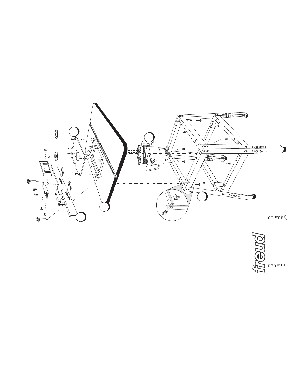
Step 6
The RTL01 Tool Stand is intended for
use with the Freud Router Table Top
or it can accommodate most bench
top tools.To mount the Freud Router
Table Top center the top on the stand
and mark the mounting hole loca-
tions. Ensure that none of the holes
are aligned with the aluminum track
or the threaded inserts of the Router
Table Top. Remove the top and drill a
1/8" X 5/8" deep pilot hole in the cen-
ter of each mark. Reposition the top
on the stand, insert the No. 10 x 3/4" screws (packaged separatley)
through the mounting holes and into the pilot holes and tighten with a
Phillips screwdriver. For use with your bench top tool a wood platform
20" x 24" must be bolted on Upper Cross Braces (platform and hard-
ware not included). Secure tools to wood platform.
Freud America, Inc. 1-800-472-7307 www.freudtools.com
IMPORTANT - PLEASE READ COMPLETE ASSEMBLY INSTRUCTIONS BEFORE YOU START.
IHGJ
This manual suits for next models
2
Other Freud Power Tools manuals
Popular Power Tools manuals by other brands

Grizzly
Grizzly KSG 220 Translation of the original instructions for use

MSW
MSW HP 2000 user manual

EINHELL HOME
EINHELL HOME TH-CD 18-2 2B Original operating instructions

Greenlee
Greenlee Fairmont F20 instruction manual

CAMPAGNOLA
CAMPAGNOLA COBRA Use and maintenance manual

Metabo
Metabo LF 724 S Original instructions