manuals.online logo
Brands
  1. Home
  2. •
  3. Brands
  4. •
  5. Frico
  6. •
  7. Heater
  8. •
  9. Frico Thermozone AGI User manual

Frico Thermozone AGI User manual

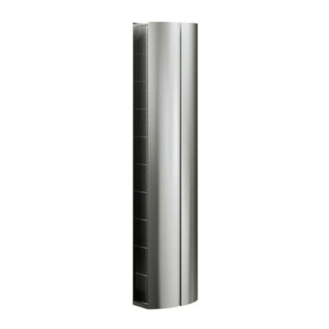
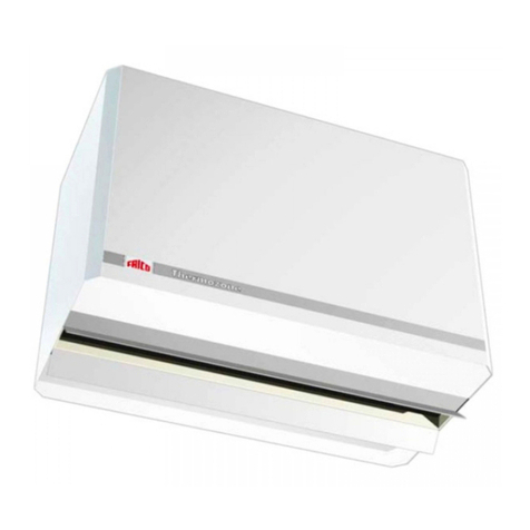
Thermozone AGI
.... 15
SE
.... 19
GB
AGI A/W
2
L
L/2
25
25
25
25
575 7575
485
185
730
300
160
M10
47
97
50
100
Type L
[mm]
DN25 DN32
AGIH2 1200 X
AGIH3 1800 X
AGIH4 2400 X
AGIH5 3000 X
AGI A/W
3
300
485
185
730
160
50
L
25
25 25
75 75575
25
47
97
100
50
Type L
[mm]
DN25 DN32
AGIV2 1200 X
AGIV3 1800 X
AGIV4 2400 X
AGIV5 3000 X
AGI A/W
4
Accessories
RTRD7
RTRD14
RTRDU7
MDC (MDCDC included)
T10
RTI2
KRT1900/KRT2800
AGB304
AV20/25
JVF20/25
TRV20/25
BPV10
SD20
TVV20/25
SD20
VR20/25
Air curtain Air curtain
AGI A/W
5
SD20
AV20/25
TRV20/25
BPV10
TVV20/25
JVF20/25
VR20/25
Water regulators
Accessories
Type RSK-nr
[SE]
VR20 672 59 98
VR25 672 59 99
TVV20 672 70 35
TVV25 672 70 36
SD20 672 70 37
TE3434
AGI A/W
6
Wiring diagrams AGI A
Ambient control option
Bridge RT-RT
if no door contact is used
To terminals
L1, L2, and L3
in slave units To terminals 5-6
in slave units
PE L1N L2 L3 N L L TK TK FS FSU1 V1 W1 RT RT
400V3N~
RTRD
Fan 1
M
3~
M
3~
M
3~
M
3~
U
V
TK
W
TK
PE
U
V
TK
W
TK
PE
U
V
TK
W
TK
PE
U
V
TK
W
TK
PE
U
V
TK
W
TK
PE
Fan 2 Fan 3 Fan 4 Fan 5
M
3~
PE L1 L2 L3 5 6 65 65 65 65
AGIV5
AGIH5
13
14
AGB
AGI A/W
7
Wiring diagrams AGI W
Water control options
Level 1
Bridge RT-RT
if no door contact is used
To terminals
L1, L2, and L3
in slave units To terminals 5-6
in slave units
PE L1N L2 L3 N L L TK TK FS FSU1 V1 W1 RT RT
400V3N~
RTRD
SD20
TVV20/25
Fan 1
M
3~
M
3~
M
3~
M
3~
U
V
TK
W
TK
PE
U
V
TK
W
TK
PE
U
V
TK
W
TK
PE
U
V
TK
W
TK
PE
U
V
TK
W
TK
PE
Fan 2 Fan 3 Fan 4 Fan 5
M
3~
PE L1 L2 L3 5 6 65 65 65 65
AGIV5
AGIH5
230V~
A/B
24 4
>t°C
62 7
T10
13
14
AGB
1
2
3
KRT1900
AGI A/W
8
Wiring diagrams AGI W
Water control options
Level 2
C°
2 3 4 5 6 7 N L1
Hi Lo RTI2
PE L1N L2 L3 N L L TK TK FS FSU1 V1 W1 RT RT
MDC
Door
contact
NL DC DC
12
11 14
21
22 24
32
31 34
230V~
230V~
400V3N~
RTRDU
1 2 3 SD20
TVV20/25
Fan 1
M
3~
M
3~
M
3~
M
3~
U
V
TK
W
TK
PE
U
V
TK
W
TK
PE
U
V
TK
W
TK
PE
U
V
TK
W
TK
PE
U
V
TK
W
TK
PE
Fan 2 Fan 3 Fan 4 Fan 5
M
3~
PE L1 L2 L3 5 6 65 65 65 65
AGIV5
AGIH5
To terminals
L1, L2, and L3
in slave units To terminals 5-6
in slave units
AGI A/W
9
Wiring diagrams AGI W
Convertible connection 230V3~
AGI A/W
10
Incoming / outgoing water temperature 80/60°C
Air temp. in = +15°C Air temp. in = +20°C
Type Fan
position
Airflow
[m³/h]
Output
[kW]
Air.temp.
out.
[°C]
Water
flow
[l/s]
Output
[kW]
Air.temp.
out
[°C]
Water
flow
[l/s]
AGIH2
AGIV2
high 7000 55,7 38,6 0,7 50,5 41,4 0,6
high 7000 50,1 36,3 0,6 45,5 39,0 0,5
AGIH3
AGIV3
high 10500 85,6 39,2 1,0 77,5 41,9 1,0
high 10500 77,0 36,8 0,9 69,8 40,0 1,0
AGIH4
AGIV4
high 14000 117,9 40,0 1,4 106,4 42,6 1,3
high 14000 106,1 37,5 1,3 95,8 40,2 1,2
AGIH5 high 17500 147,1 40,0 1,8 132,8 42,5 1,6
AGIV5 high 17500 132,4 37,5 1,6 119,5 40,2 1,4
Incoming / outgoing water temperature 70/40°C
Air temp. in = +15°C Air temp. in = +20°C
Type Fan
position
Airflow
[m³/h]
Output
[kW]
Air.temp.
out.
[°C]
Water
flow
[l/s]
Output
[kW]
Air.temp.
out
[°C]
Water
flow
[l/s]
AGIH2
AGIV2
high 7000 37,2 30,8 0,3 31,8 33,5 0,3
high 7000 33,5 29,2 0,1 28,6 32,2 0,1
AGIH3
AGIV3
high 10500 56,6 31,0 0,5 48,0 33,6 0,4
high 10500 50,9 29,4 0,2 43,2 32,2 0,2
AGIH4
AGIV4
high 14000 77,9 31,5 0,6 66,3 34,1 0,5
high 14000 70,1 29,9 0,3 59,7 32,7 0,2
AGIH5 high 17500 96,9 31,5 0,8 82,5 34,0 0,7
AGIV5 high 17500 87,2 29,8 0,4 74,2 32,6 0,3
Incoming / outgoing water temperature 60/40°C
Air temp. in = +15°C Air temp. in = +20°C
Type Fan
position
Airflow
[m³/h]
Output
[kW]
Air.temp.
out.
[°C]
Water
flow
[l/s]
Output
[kW]
Air.temp.
out
[°C]
Water
flow
[l/s]
AGIH2
AGIV2
high 7000 33,7 29,3 0,4 28,4 32,1 0,3
high 7000 30,3 27,9 0,1 25,6 30,9 0,1
AGIH3
AGIV3
high 10500 51,5 29,6 0,6 43,2 32,2 0,5
high 10500 46,3 28,1 0,2 38,9 31,0 0,2
AGIH4
AGIV4
high 14000 71,0 30,1 0,9 59,5 32,6 0,7
high 14000 64,0 28,6 0,3 53,6 31,4 0,2
AGIH5 high 17500 88,5 30,0 1,1 74,1 32,6 0,9
AGIV5 high 17500 79,7 28,5 0,3 66,7 31,3 0,3
Incoming / outgoing water temperature60/30°C
Air temp. in = +15°C Air temp. in = +20°C
Type Fan
position
Airflow
[m³/h]
Output
[kW]
Air.temp.
out.
[°C]
Water
flow
[l/s]
Output
[kW]
Air.temp.
out
[°C]
Water
flow
[l/s]
AGIH2
AGIV2
high 7000 25,7 25,9 0,2 19,8 28,4 0,2
high 7000 23,1 24,8 0,1 17,8 27,6 0,1
AGIH3
AGIV3
high 10500 38,6 26,0 0,3 28,9 28,2 0,2
high 10500 34,7 24,8 0,1 26,0 27,4 0,1
AGIH4
AGIV4
high 14000 53,3 26,3 0,4 40,9 28,7 0,3
high 14000 48,0 25,5 0,2 36,8 27,8 0,2
AGIH5 high 17500 66,2 26,2 0,5 48,4 28,2 0,4
AGIV5 high 17500 59,5 25,1 0,2 43,6 27,4 0,2
Output charts Water WL
AGI A/W
11
Incoming / outgoing water temperature 55/35°C
Air temp. in = +15°C Air temp. in = +20°C
Type Fan
position
Airflow
[m³/h]
Output
[kW]
Air.temp.
out.
[°C]
Water
flow
[l/s]
Output
[kW]
Air.temp.
out
[°C]
Water
flow
[l/s]
AGIH2
AGIV2
high 7000 28,2 27,0 0,3 22,8 29,7 0,3
high 7000 25,4 25,8 0,1 20,6 28,7 0,1
AGIH3
AGIV3
high 10500 43,0 27,1 0,5 34,6 29,8 0,4
high 10500 38,6 25,9 0,2 31,1 28,8 0,1
AGIH4
AGIV4
high 14000 59,1 27,5 0,7 47,6 30,1 0,6
high 14000 53,2 26,3 0,2 42,9 29,1 0,2
AGIH5 high 17500 73,5 27,5 0,9 59,3 30,1 0,7
AGIV5 high 17500 66,19 26,3 0,3 53,3 29,1 0,2
AGI A/W
12
Output charts water WH
Incoming / outgoing water temperature 130/70°C
Air temp. in = +15°C Air temp. in = +20°C
Type Fan
position
Airflow
[m³/h]
Output
[kW]
Air.temp.
out.
[°C]
Water
flow
[l/s]
Output
[kW]
Air.temp.
out
[°C]
Water
flow
[l/s]
AGIH2
AGIV2
high 7000 59,9 40,4 0,2 55,8 43,7 0,2
high 7000 53,9 38,0 0,1 50,2 41,4 0,2
AGIH3
AGIV3
high 10500 92,9 41,3 0,4 86,6 44,5 0,3
high 10500 83,6 38,9 0,3 77,9 42,1 0,3
AGIH4
AGIV4
high 14000 128,4 42,2 0,5 119,7 45,4 1,0
high 14000 115,6 39,8 0,4 107,7 42,9 0,4
AGIH5 high 17500 159,7 42,1 0,7 148,9 45,3 0,6
AGIV5 high 17500 143,7 39,7 0,6 134,0 42,8 0,5
Incoming / outgoing water temperature 110/80°C
Air temp. in = +15°C Air temp. in = +20°C
Type Fan
position
Airflow
[m³/h]
Output
[kW]
Air.temp.
out.
[°C]
Water
flow
[l/s]
Output
[kW]
Air.temp.
out
[°C]
Water
flow
[l/s]
AGIH2
AGIV2
high 7000 61,0 40,9 0,5 57,1 44,2 0,5
high 7000 54,9 38,3 0,4 51,4 41,8 0,4
AGIH3
AGIV3
high 10500 95.0 41,9 0,8 88,8 45,1 0,7
high 10500 85,5 39,2 0,7 80,0 42,6 0,6
AGIH4
AGIV4
high 14000 131,2 42,8 1,1 122,8 46,0 1,0
high 14000 118,1 40,1 0,9 110,5 43,5 0,9
AGIH5 high 17500 163,7 42,8 1,4 153,1 46,0 1,3
AGIV5 high 17500 147,4 40,1 1,2 137,8 43,4 1,1
Incoming / outgoing water temperature 90/70°C
Air temp. in = +15°C Air temp. in = +20°C
Type Fan
position
Airflow
[m³/h]
Output
[kW]
Air.temp.
out.
[°C]
Water
flow
[l/s]
Output
[kW]
Air.temp.
out
[°C]
Water
flow
[l/s]
AGIH2
AGIV2
high 7000 49,8 36,2 0,6 46,0 39,5 0,6
high 7000 45,5 34,1 0,5 41,4 37,6 0,5
AGIH3
AGIV3
high 10500 78,1 37,1 1,0 71,9 40,3 0,9
high 10500 70,3 34,9 0,8 64,7 38,3 0,8
AGIH4
AGIV4
high 14000 107,5 37,8 1,3 99,0 41,0 1,2
high 14000 96,7 35,6 1,2 89,1 38,9 1,1
AGIH5
AGIV5
high
high
17500
17500
134,1
120,7
37,8
35,5
1,5
1,5
123,5
111,1
41,0
38,9
1,1
1,3
Incoming / outgoing water temperature80/60°C
Air temp. in = +15°C Air temp. in = +20°C
Type Fan
position
Airflow
[m³/h]
Output
[kW]
Air.temp.
out.
[°C]
Water
flow
[l/s]
Output
[kW]
Air.temp.
out
[°C]
Water
flow
[l/s]
AGIH2
AGIV2
high 7000 41,6 32,7 0,5 37,6 36,0 0,5
high 7000 37,4 30,9 0,5 33,9 34,4 0,4
AGIH3
AGIV3
high 10500 64,7 33,3 0,8 58,5 36,5 0,7
high 10500 58,2 31,5 0,7 52,6 34,9 0,9
AGIH4
AGIV4
high 14000 89,5 34,0 1,1 80,6 37,1 1,0
high 14000 80,5 32,1 1,0 72,6 35,4 0,9
AGIH5
AGIV5
high 17500
17500
111,6
100,4
33,9
32,1
1,4
1,2
100,5
90,4
37,1
35,4
1,2
1,1
AGI A/W
13
Pressure drop water
Water pressure drop over AGI WL water coil.
Pressure drop [kPa]
Pressure drop [bar]
Water flow [m³/h]
Water flow [l/s]
The pressure drop is calculated for an average temperature of 70°C (PVV 80/60).
For other water temperatures, the pressure drop is multiplied by the factor K.
Average temp. water °C 40 50 60 70 80 90
K 1,10 1,06 1,03 1,00 0,97 0,93
Water pressure drop over AGI WH water coil
Water flow [l/s]
Water flow [m³/h]
Pressure drop [kPa]
Pressure drop [bar]
AGI2WH
0,1
10
100
1
1,0 10
AGI3WH
AGI4WH
AGI5WH
0,01
0,1
1
101,00,1
AGI2WL
0,1
10
100
1
1,0 10
AGI3WL
AGI4WL
AGI5WL
0,1 1,0 10
1
0,1
0,01
AGI A/W
14
Type Output*3
[kW]
Airflow
[m³/h]
∆t*¹,*³
[°C]
Sound
level*²
[dB(A)]
Voltage
[V]
Amperage
[A]
Weight
[kg]
AGIH/V2 56/50 7000 21 69 400V3~ 2,4 82
AGIH/V3 86/77 10500 22 71 400V3~ 3,5 125
AGIH/V4 118/106 14000 23 72 400V3~ 4,7 165
AGIH/V5 147/132 17500 22 73 400V3~ 5,9 205
Technical specifications | Thermozone AGI W with water heat
Protection class AGI A/W : IP54.
Technical specifications | Thermozone AGI A with ambient  3
Type Airflow
[m³/h]
Sound
level*²
[dB(A)]
Voltage
Amperage
(control)
Voltage
Amperage
(heat)
Weight
[kg]
AGIH/V2 7000 69 400V3~/2,4A 2,4 51
AGIH/V3 10500 71 400V3~/3,5A 3,5 75
AGIH/V4 14000 72 400V3~/4,7A 4,7 97
AGIH/V5 17500 73 400V3~/5,9A 5,9 120
GB
*1) ∆t = temperature rise of passing air at maximum heat output and lowest/highest airflow.
*2) Conditions: Distance to the unit: 5 metres. Directional factor: 2. Equivalent absorption area: 200 m2.
*3) Applicable at water temperature 80/60 °C, air temperature, in +15 °C.
Assembly and operating instructions
General Instructions
Read these instructions carefully before
installation and use. Keep this manual for
future reference.
The guarantee is only valid if the units
are used in the manner intended by the
manufacturer and in accordance with the
Frico mounting and operating instructions.
Application area
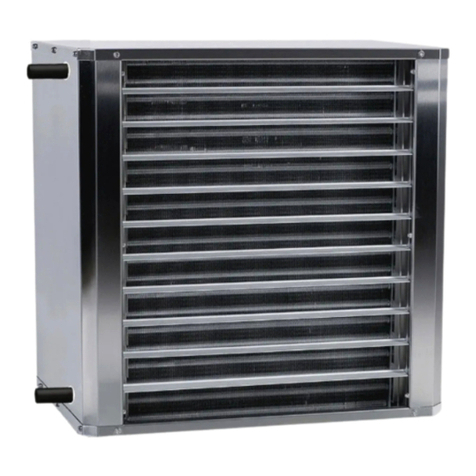
The Thermozone AGI air curtain is supplied
with ambient heat or water coil and is
intended to be installed above industrial- and
warehouse doors up to 6,0 meters height.
Protection class IP.
Function
Air is drawn in at the rear of the unit and
blown out downwards so that it shields the
door opening and minimizes heat loss. To
achieve the optimum curtain effect the
unit must extend the full width of the door
opening.
The grille for directing exhaust air is
adjustable and is normally angled outwards to
achieve the best protection against incoming
cold air.
The efficiency of the air curtain depends
on the air temperature, pressure differences
across the doorway and any wind pressure.
NOTE! Negative pressure in the building
considerably reduces the efficiency of the air
curtain. The ventilation should therefore be
balanced.
Mounting
1. Place the air curtain in the correct position.
2. Mark the holes and remove the air curtain.
3. Drill holes into the floor and replace the air
curtain.
4. Screw the frame to the floor.
See fig. 1.
The unit is installed vertical or horisontal as
close to the door as possible.
For the protection of wider doorways, several
units can be mounted next to each other.
Ensure that the front panel/service hatch
is accessible and can be fully opened. For
minimum distance see fig. 2
Electrical installation
The installation, which should be preceded by
an omnipolar switch with a contact separation
of at least 3 mm, should only be wired by a
competent electrician, in accordance with the
latest edition of IEE wiring regulations and in
accordance with this instructions. The unit is
connected to a connection box on the side of
the air curtain, below the pipe connections.
Water coil connection (AGI W)
The installation must be carried out by an
authorised installer. The water coil has copper
tubes with aluminium fins and is suitable for
connection to a closed water heating system.
The heating coil must not be connected to
a mains pressure water system or an open
water system.
Note that the unit should be preceded by a
regulating valve, see eg Frico valve assemblies.
The pipe connections (1" and 1 1/2",
internal thread) are connected on the top side
of the unit.
The connections to the coil must be
equipped with shutdown valves to enable easy
disassembly.
Adjustment of air flow
The direction and speed of the air flow
should be adjusted considering the load on
the opening. Compressive forces affect the
air stream and make it bend inwards into the
premises (when the premises are heated and
the outdoor air is cold). The air stream should
therefore be directed outwards to withstand
the load. (Generally speaking, the higher the
load, the bigger the angle needed.)
Basic setting of fan speed
The fan speed when the door is open is set
using the speed control. Note that the air flow
direction and speed may need fine adjustment
depending on the loading of the door.
AGI A/W
19
Filter (AGI)
The distance between the coil plates protects
against dirt and blockage and makes a
separate filter unnecessary.
Service, repairs and maintenance
For all service, repair and maintenance first
carry out the following:
1.Disconnect the power supply. Note! Units
with electrical heaters can be supplied from
more than one connection.
2.The front panel/service hatch is opened by
slackening off the screws on the unit.
Maintenance
Since fan motors and other components are
maintenance free, no maintenance other
than regular cleaning is necessary. The
frequency of cleaning can vary depending on
local conditions, but undertake cleaning at
least twice a year. Inlet and exhaust grilles,
impeller and elements can be vacuum cleaned
or wiped using a dry cloth. Use a brush when
vacuuming to prevent damaging sensitive
parts. Avoid the use of strong alkaline or
acidic cleaning agents.
Overheating
The motors in all the air curtain units
have a built-in thermal safety cut-out to
protect against overheating. This will reset
automatically once the motor has cooled.
Fan replacement
1.Determine which of the fans is not
functioning.
2.Disconnect the cables to the relevant fan.
3.Remove the screws securing the fan and lift
the fan out.
4.Install the new fan in reverse order to the
above.
Changing the water coil (AGI W)
1. Turn of the units water supply.
2. Disconnect the cables to the water coil.
3. Remove the mounting screws securing the
water coil in the unit and lift the water coil
out.
4 Install the new water coil in reverse order to
the above.
Draining the water coil (AGI W)
The drain valve is on the underside of the coil
on the connector side. It can be accessed via
the service hatch.
Troubleshooting
If the fans are not working or not blowing
enough, check the following:
• Operating power supply to the unit;
check fuses, circuit-breaker, time
switch/thermostat (if any) that starts
and stops the unit.
• That the speed regulator is correctly
set.
• That any position limit switch is
working.
• That the thermal safety cut-out for the
motors has not been deployed.
• That the intake grille/filter is not dirty.
If there is no heat, check the following:
• Check that the settings for the
thermostat, switches etc. are set so that
the unit can produce heat.
For units with water coil, also check the
following:
• That the water coil is bled.
• That there is a sufficient water flow.
• That the incoming water is sufficiently
hot.
If the error cannot be fixed, please contact a
qualified service technician.
Safety
• Keeptheareasaroundtheairintake
and exhaust grilles free from possible
obstructions!
• Duringoperationthesurfacesoftheunit
are hot!
• Theunitmustnotbefullyorpartially
covered with clothing, or similar
materials, as overheating can result in a
rerisk!
• Thisapplianceisnotintendedforuseby
persons (including children) with reduced
physicalormentalcapabilities,orlack
ofexperienceandknowledge,unlessthey
AGI A/W
20
have been given supervision or instruction
concerning use of the appliance by
a person responsible for their safety.
Children should be supervised to ensure
that they do not play with the appliance.
Technical data is shown on page 14.
AGI A/W
21
For latest updated information, see: www.frico.se
20090218 JV/HH
Main office
Frico AB Tel: +46 31 336 86 00
Box 102 Fax: +46 31 26 28 25
SE-433 22 Partille [email protected]
Sweden www.frico.se
Norway
Frico AS Tel: +47 23 37 19 00
P.B 82 Alnabru Fax: +47 23 37 19 10
NO-0614 Oslo mailbo[email protected]
Norway www.frico.no
France
Frico SAS Tel: +33 4 72 42 99 42
53 avenue Carnot Fax: +33 4 72 42 99 49
69250 Neuville sur Saône inf[email protected]
France www.frico.fr
Spain
Frico repr. office in Spain Tel: +34 91 887 60 00
C/Montecarlo Nº 14 Fax: +34 91 887 60 00
P.I. Uranga
ES-29942 Fuenlabrada mailbo[email protected]
Spain www.frico.se
Netherlands
Frico BV Tel: +31 492 590 786
Wethouder van Nunenst. 12d Fax: +31 492 590 787
5706 TK Helmond info@fricobv.nl
Netherlands www.fricobv.nl
For latest updated information, see: www.frico.se
United Kingdom
Frico Limited Tel: +44 (0)121 322 0854
72 Cheston Road Fax: +44 (0)121 322 0858
B7 5EJ inf[email protected]
UK-Birmingham www.frico.co.uk
United Kingdom
Russia
Frico repr. office in Russia Tel: +7 495 238 63 20
Lavrov per. 6 +7 495 676 44 48
RU-109044 Moscow Fax: +7 495 676 44 48
Russia [email protected]u
www.frico.se
China
Frico repr. office in China Tel: +86 21 62569900
Rm 702, Mod. Comm. Build. Fax:+86 21 62554747
201, New Jin qiao Rd [email protected]
201206 Shanghai www.frico.com.cn
P.R. China
Austria
Frico GmbH Tel: +43 1 616 24 40-0
Kolpingstraße 14
1232 Wien office@altexa-frico.at
Austria www.altexa-frico.at
Switzerland
Gutekunst AG Tel: 061 706 96 26 (nat)
Baselstrasse 22 Fax: 061 706 96 20 (nat)
CH-4144 Arlesheim info@gutekunst-ag.ch
Switzerland www.gutekunst-ag.ch

Other Frico Heater manuals

Frico IHC Series User manual

Frico

Frico IHC Series User manual

Frico Infratower IHA30 P Series User manual

Frico

Frico Infratower IHA30 P Series User manual

Frico RAR3500 Series User manual

Frico

Frico RAR3500 Series User manual

Frico Sierra User manual

Frico

Frico Sierra User manual

Frico PA3500 Series User manual

Frico

Frico PA3500 Series User manual
Frico Infraduo IHD17 User manual

Frico

Frico Infraduo IHD17 User manual

Frico AR3215C User manual

Frico

Frico AR3215C User manual

Frico SWT Series User manual

Frico

Frico SWT Series User manual

Frico AREC3200C User manual

Frico

Frico AREC3200C User manual

Frico SIReFAEMX User manual

Frico

Frico SIReFAEMX User manual

Frico Ruwen User manual

Frico

Frico Ruwen User manual

Frico Elektra H Series User manual

Frico

Frico Elektra H Series User manual

Frico Infrapalm IHPA User manual

Frico

Frico Infrapalm IHPA User manual

Frico Tiger 2 kW User manual

Frico

Frico Tiger 2 kW User manual

Frico AC Corinte ACCS Series User manual

Frico

Frico AC Corinte ACCS Series User manual

Frico Thermozone AR300 Series User manual

Frico

Frico Thermozone AR300 Series User manual

Frico Thermocassette HP3N User manual

Frico

Frico Thermocassette HP3N User manual

Frico SIReAA User manual

Frico

Frico SIReAA User manual

Frico Thermocassette CTS User manual

Frico

Frico Thermocassette CTS User manual

Frico PAEC3200C-NA Series User manual

Frico

Frico PAEC3200C-NA Series User manual

Frico Tiger 20 kW User manual

Frico

Frico Tiger 20 kW User manual

Frico HDI55 User manual

Frico

Frico HDI55 User manual

Frico PCW Series User manual

Frico

Frico PCW Series User manual

Frico Thermozone ACC10 User manual

Frico

Frico Thermozone ACC10 User manual

Popular Heater manuals by other brands

Altecnic Matrix Maxi Installation, operation & maintenance instructions

Altecnic

Altecnic Matrix Maxi Installation, operation & maintenance instructions

Dimplex OFCB5 Installation and operating instructions

Dimplex

Dimplex OFCB5 Installation and operating instructions

Sealey AB458.V2 instructions

Sealey

Sealey AB458.V2 instructions

Creda Newera TSR18CW Assembly instruction

Creda

Creda Newera TSR18CW Assembly instruction

LVI Epok H Instructions for fitting and use

LVI

LVI Epok H Instructions for fitting and use

Rointe Series C 603 instruction manual

Rointe

Rointe Series C 603 instruction manual

PVG SRE 1330 TC-2 operating manual

PVG

PVG SRE 1330 TC-2 operating manual

Dimplex FX 20VL Installation and operating instructions

Dimplex

Dimplex FX 20VL Installation and operating instructions

EOS P1+ Assembly and operating instruction

EOS

EOS P1+ Assembly and operating instruction

GiveBest HPQ15C-EA user manual

GiveBest

GiveBest HPQ15C-EA user manual

TREVIDEA G3 FERRARI TEPOR user manual

TREVIDEA

TREVIDEA G3 FERRARI TEPOR user manual

Protemp PT-70-SS-EU User's manual and operating instructions

Protemp

Protemp PT-70-SS-EU User's manual and operating instructions

Thermal Trend FENIX Installation and user manual

Thermal Trend

Thermal Trend FENIX Installation and user manual

Goldair GCT200 operating instructions

Goldair

Goldair GCT200 operating instructions

Bestron WINTER WARM ACV3000T instruction manual

Bestron

Bestron WINTER WARM ACV3000T instruction manual

Termozeta TZR11 instruction manual

Termozeta

Termozeta TZR11 instruction manual

Tansun Quartzheat Carnival CARN4 1X750H Reference manual

Tansun Quartzheat

Tansun Quartzheat Carnival CARN4 1X750H Reference manual

Russell Hobbs RHCVH4002 manual

Russell Hobbs

Russell Hobbs RHCVH4002 manual

manuals.online logo
manuals.online logoBrands
  • About & Mission
  • Contact us
  • Privacy Policy
  • Terms and Conditions

Copyright 2025 Manuals.Online. All Rights Reserved.