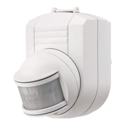
FRIEDLAND SPECTRA Lite User manual

Lite
3
List Number L110N WHI
BEFORE STARTING ANY INSTALLATION WORK, PLEASE READ CAREFULLY
TOOLS NEEDED
●Drill and 6mm Masonry Drill Bit
●
Wire cutters and Wire Strippers
●No.2 philips Screwdriver
●Terminal or Electricians Screwdriver
●Large Flat Bladed screwdriver
PARTS INCLUDED
- Bulkhead PIR light
- Instruction Manual
- Accessory pack
Instruction Manual
SAFETY
Always follow the manufacturers advice when using power tools, steps, ladders etc. and wear suitable
protective equipment (e.g. safety goggles when drilling holes). Before drilling holes in walls, check forhidden
electricity cables and water pipes, the use of a cable/pipe locater maybe advisable if in doubt.
The mains supply to this product should be installed by a competent person (e.g. a qualified electrician) in
accordance with these instructions and in accordance with the appropriate clauses of the current edition of
the IEEE wiring regulations (BS7671).
DANGER - 230 VOLTS. To prevent the risk of electrocution, always turn off the mains electricity supply
before commencing any work on the installation or opening the detector.
It is essential that all connections are made as instructed, that cables are not stressed and that terminals
are fully tightened.
Suitable for connection to fixed luminaires only. Internal and connected lamps loads must not exceed the
specified maximums. This product is suitable for wall mounting only.

Eng
1
Fig. 3
Fig. 2
ACROSS its field of vision [Fig. 2], rather
than movement directly toward it [Fig. 3] -
so if possible, mount the PIR facing
ACROSS the approach to your property.
After choosing a suitable location (see
previous section) install the unit as follows:
The unit is suitable for connection to a 230V
AC 50Hz electricity supply. It is suggested that
3-core round flexible cable of 1mm2gauge
is used. A double pole switch should be
installed to switch the power to the unit ON
& OFF. This allows the detector to be easily
switched off when not required or for
maintenance purposes.
MOUNTING, WIRING
2& CONNECTION
IMPORTANT
Switch off the electricity at the fuse box by
removing the relevant fuse or switching off
the circuit breaker before proceeding with
the installation
SELECTING A
1LOCATION
Fig. 1
Your PIR Detector has a number of
detection zones at various horizontal and
vertical angles, as shown. A moving human
body crossing or entering one of the zones
activates the Detector. Mount the Detector
at a height of 2m for the best all-round
coverage [Fig. 1] - it may be positioned up
to 4m high for a greater detection range,
but the detection pattern will be less
effective.
Careful positioning of the tilt and swivel
Detector head is needed to ensure optimum
performance. When performing the WALK
TEST [Section 3], the angle of the head
may require slight adjustment, particularly
when mounting your PIR Detector higher
than the recommended 2m.
Also note that the PIR Detector is
much more sensitive to movement

2
Remove the diffuser using a flat bladed
screwdriver to release the clips on both sides
(Fig 4).
Detach the connection cover by removing
the fixing screw.
Ensure the unit is in an upright position with
the sensor module at the bottom.
Mark the position of the fitting holes.
Drill the holes. Insert the wall plugs into the
holes.
PIERCE & PASS THE CABLE THROUGH
THE GROMMET BEFORE PROCEEDING
Secure the unit to the wall using screws
provided. Do not overtighten the screws as
this could damage the unit.
CONNECTION
Pass the mains supply cable around the
back of the lampholder for ease of wiring.
Connect the cable to the terminal block on
the unit as follows (see connection diagram):
NEUTRAL (Blue) N
LIVE (Brown) L
Note: the unused earth wire mut be insulated
and placed in the termination area.
For class 1 lights in series with the switched
output of the lamp make sure that the earth
continuity to the lights is provided, use
external junction boxes, if necessary.
Ensure that the connections are secure.
Re-attach the connection cover.
Install the lightbulb (not supplied).
Fit the diffuser back onto the main body of
the unit, ensuring it clicks firmly in place
YOU CAN CONNECT ADDITIONAL LIGHT
UNITS TO SPECTRA LITE.
The PIR detector will control the additional
light as well as the built in lamp. Ensure the
total wattage of lamps connected does not
exceed the maximum switchable load.
Fig 4
LN
L1
LIVE
NEUTRAL
Indoor switch
for permanent
off override
(optional)
LN
L1
LN
L1
LIVE
NEUTRAL
LIVE
NEUTRAL
Single pole 2 gang switch
Lamp
PERMANENT OFF: S1 OPEN S2 OPEN
AUTO MODE: S1 CLOSED S2 OPEN
PERMANENT ON: S1 OPEN OR CLOSED S2 CLOSED
Indoor switch for permanent
off override (optional)
Lamp
Lamp
Lamp

3
OPERATION &
3TESTING
Walk testing
The detector will rotate from left to right.
Adjust the detector to point in the desired
direction.
When the installation procedure is complete,
the unit is ready for testing.
The Walk Test procedure is as follows:
Step 1
Set the two adjustment controls on the
underside of the PIR to the following
positions:
TIME - Fully anti-clockwise
LUX-Fully clockwise
With these settings, the unit will operate
during daytime as well as at night,
illuminating the floodlight for approx.
5 seconds each time movement is
detected. This allows testing to be carried
out following installation in order to establish
the best position for the sensor head,
ensuring optimum performance.
Step 2
Apply the power by switching on the circuit
breaker/internal wall switch. The lamp will
immediately illuminate as the system goes
through its ‘warm-up’ period. After
approximately 30 secs - 1 min the lamp
will
extinguish. Please try to remain outside
the
detection area during the warm-up period.
Step 3
Walk across the detection area approx. 5
metres from the unit. As you cross the first
detection ‘zone’ the lamp should illuminate.
Now stand still until the lamp extinguishes
(this should take approx. 5 seconds)
Step 4
Start moving again. As you cross each
‘zone’ the lamp should illuminate.
Step 5
Repeat Steps 3 & 4, walking at various
distances and angles to the unit. This will
help you to establish the detection pattern.

4
Step 6
Carry out Walk Tests and adjustments until
you are happy with the coverage area.
Setting up for automatic
operation
When Walk Tests are complete, the unit can
be set for automatic operation as follows:
Step 1
The TIME setting controls how long the
lamp load remains illuminated following
activation and after no further movement is
detected. The minimum time (TIME control
fully anti-clockwise) is approx. 5 seconds,
whilst the maximum time (TIME control fully
clockwise) is approx 15 minutes. Set the
control to the desired setting between these
limits.
Step 2
The LUX control determines the level of
darkness required for the unit to start
operating each evening. The setting is best
achieved by the following procedure:
- Set the LUX control knob fully
anti-clockwise. Wait until evening.
- When the ambient light level reaches the
level of darkness at which you wish the lamp
to become operative (i.e. at dusk), slowly
rotate the control in a clockwise direction
until a point is reached where the lamp
illuminates. Leave the control set at this
point.
At this position, the unit should become
operative at approximately the same level
of darkness each evening. Observe the
operation of the unit over a period of a few
days. If you find that the unit is starting to
operate too early (i.e. when it is quite light),
adjust the control slightly anti-clockwise.
If the unit starts to operate too late
(i.e. only when it is very dark), adjust the
control slightly clockwise. Continue to
adjust until the unit operates as desired.
MASKING THE SENSOR LENS
To reduce the sensor coverage,
preventing detection in unwanted areas,
mask the sensor lens using electricians
tape or similar (see Fig. 5). For your
information, the top section of the lens
covers long range detection, the bottom
covers short range. Similarly, the left and
right lens sections cover the left and right
detection areas respectively.
Fig 5
5
TROUBLESHOOTING GUIDE
4
The unit may be suffering from false activation. Cover the sensor lens
completely with a thick cloth. This will prevent the sensor from “seeing”
anything. If the unit now switches off after the set time duration and does not
re-activate, this indicates that the problem was caused by false activation. The
problem may be solved by slightly adjusting the direction / angle of the sensor
head(see previous section). You may not be allowing the unit time to complete
it’s warm-up period. Stand well out of the detection range and wait (the warm-
up period should never exceed 10 minutes). Occasionally, winds may activate
the sensor. Sometimes passages between building etc. can cause a “wind
tunnel” effect.
Ensure the unit is not positioned so as to allow detection of cars/people using
public through areas adjacent to your property.
Thoroughly check that your wiring is correct according to the wiring diagram.
Be sure you allow the unit to complete its warm-up period - stay well out of the
detection area and wait (warm-up should never take longer than 10 minutes).
Check power is ON. If so, turn power OFF and check wiring is correct, and that
no connections are loose. Check that lamps in the system have not failed, and
that they are properly seated in their holders.
Ambient light level may be too high in operational area. Adjust the LUX control
slowly clockwise until lamp illuminates [See Section 3 for details].
Ambient light level may be too low in operational area. During daylight, turn the
LUX control slightly anti-clockwise. When lamp extinguishes, enter detection
area, if PIR still activates, adjust LUX further in anti-clockwise direction and
enter the detection zone again. Repeat procedure until PIR does not activate
[See Section 3 for details].
Check suitability of location - see Section 1 for advice, and reposition PIR if
necessary.
PIR sensors are influenced by climatic conditions. The colder the ambient
temperature, the more effective the sensor will be. You may need to make
seasonal adjustments to the sensor head position to ensure trouble-free
operation all year round.
REMEMBER Always ensure the mains supply to the unit is isolated before
removing covers which allow access to live parts.
Light stays ON all the
time at night, or PIR
activates for no reason
at random.
Light stays ON all the
time day and night
PIR Detector will not
operate at all
The PIR Detector will
not operate at night
Unit activates in
daytime
PIR coverage is
poor/sporadic
Detection range
changes from day
to day
PROBLEM SOLUTION

Detection Range Up to 8 metres
Angle of Detection 110°
Power supply 220-240V AC~50Hz
Internal Lamp 60W max
Maximum Switchable Load 2000W Tungsten Filament or
2000W Tungsten Halogen or
500W Fluorescent
Time On Adjustment 5 seconds - 15 minutes
Lux Level Adjustment Day & night or night only operation
Environmental Protection IP44. Suitable for outdoor use
The PIR sensor emits no radiation & is not harmful to people, animals or plants
TECHNICAL SPECIFICATIONS
This product complies with the European Low Voltage Directive 73/23/EEC and EMC
Directive 89/336/EEC
6
Eng

DISPOSAL:
At the end of their useful life the packaging and product should be disposed of via a
suitable Recycling Centre. Do not dispose of with your normal household waste.
DO NOT BURN.
GUARANTEE
Novar ED&S undertakes to replace or repair at its discretion goods should they become
defective within 2 years solely as a result of faulty materials and workmanship.
Understandably if the product has not been installed, operated or maintained in
accordance with the instructions, has not been used appropriately or if any attempt has
been made to rectify, dismantle or alter the product in any way the guarantee will be
invalidated.
The guarantee states Novar ED&S entire liability. It does not extend to cover consequential
loss or damage or installation costs arising from the defective product.
This guarantee does not in any way affect the statutory or other rights of a consumer.
If an item develops a fault within the guarantee period, it should be returned to the point of
sale with:
1) Proof of purchase.
2) A full description of the fault.
Friedland is a trademark of Novar ED&S.
HELPLINE
If you have any problems with this product, please call the Helpline on 01268 563066
(Lines open 9.00am to 5.00pm, Monday to Friday)
Friedland, Novar Electrical Devices and Systems
The Arnold Centre, Paycocke Road, Basildon, Essex. SS14 3EA
www.friedland.co.uk
7
Table of contents
Other FRIEDLAND Security Sensor manuals

FRIEDLAND
FRIEDLAND Spectra Wirefree Product information sheet

FRIEDLAND
FRIEDLAND Spectra Lite L230N BLK User manual

FRIEDLAND
FRIEDLAND Magnetic Contact User manual

FRIEDLAND
FRIEDLAND Spectra Plus L420N WHI User manual

FRIEDLAND
FRIEDLAND D918S Libra+ User manual

FRIEDLAND
FRIEDLAND SPECTRA WIREFREE 6500 User manual

FRIEDLAND
FRIEDLAND Spectra Plus L420N WHI User manual

FRIEDLAND
FRIEDLAND SPECTRA 140 User manual