manuals.online logo
Brands
  1. Home
  2. •
  3. Brands
  4. •
  5. FRIEDLAND
  6. •
  7. Security Sensor
  8. •
  9. FRIEDLAND SPECTRA WIREFREE 6500 User manual

FRIEDLAND SPECTRA WIREFREE 6500 User manual

LN
L1 N
4
3
21
B
A
Fixing
holes
System code
slider switches Drain hole
position
Drain hole
position
Channel for run-
ning cable from
cable entry point
2 or 3 to
Terminal B
1,2,4 : Cable entry points
3 : Rear cable entry point
fig 1
4
140oPIR Movement Detector/Transmitter and Receiver
For easy installation and earlier detection
Terminal B
for connection
to light fitting
Terminal A
for connection
to power supply
MAINS POWERED RECEIVER UNIT
Fixing
holes
System code
slider switches
9v Alkaline
Battery
B ATTERY POWERED
140°PIR MOVEMENT
DETECTO R
fig 2
12345678
ON
LN
L1 N
12345678
ON
fig 4
fig 3
LN
L1 N
AB
14
LN
L1 N
A
B
1
4
LN
L1 N
A
B
21
4
fig 5
fig 6
LN
L1 N
A
B
fig 8
L
N
L1N
AB
fig 7
fig 9 fig 10
15S 15M
1M
2M 3M 6M
12M
9M
15s 15m
12345678
ON
12M
12M
0
00
fig 11 fig 12
fig 13
fig 14
fig 18
fig 19 fig 20 fig 21
fig 22
fig 23
fig 24
fig 25
fig 27
fig 26
fig 29
fig 30
fig 28
fig 31
Fixing
holes
Fixing
holes
6500
1. SPECTRA WIREFREE PIR MOVEMENT DETECTOR &
RECEIVER SYSTEM
Your Spectra Wirefree Passive Infrared (PIR) Movement Detector and Receiver System
provides you with an advanced system which can utilise an existing light, or any new
exterior lamp you choose. It gives you the freedom to fit any style of light fitting, and still
enjoy the peace of mind and convenience of effective automatic lighting.
No Wires! - The system uses radio technology to activate the light. With no need for
wiring, the PIR Detector can be easily located wherever it is needed within 50
metres of its receiver - which in turn controls the light. Even mains garden lighting
can easily be converted to automatic operation.
This system uses radio wave technology to activate mains lighting. Radio wave
transmission can be affected by thick walls, metal window frames, aluminium rein-
forced UPVC windows and doors, metallic parts of house structures and similar
objects. Whilst the majority of installations are not adversely affected, you may
have to experiment a little to discover the best location for your PIR/Transmitter
and Receiver Unit.
The PIR Movement Detector/Transmitter and the Receiver Unit are weatherproof,
and suitable for outdoor installation.
2. PACK CONTENTS
■1 wirefree (battery powered) 140° coverage PIR Movement Detector with built-
in radio transmitter. Requires 1 x PP3/6LR61 9v Alkaline Battery
■1 mains powered receiver unit
■4 plastic wallplugs plus 4 securing screws
■
4 rubber cable grommets (2 with hole pierced, 2 unpierced)
■2 fixing screw sealing plugs
■2 slot-in PIR lens screening panels
3. ELECTRICAL CABLING TO THE RECEIVER UNIT
The Receiver Unit requires connection to a 220-240V 50Hz mains electricity supply.
The Receiver Unit is designed to accept most types of 10Arated 2 or 3 core cable up to
14mm in diameter. It is recommended that only one cable is fitted through a single grommet.
Except when installed in a dry and protected environment, the Receiver Unit is not suitable for
connection using separate single core wires - the kind sometimes found in conduit cabling. The
receiver unit is not designed for direct connection to conduit.
4. TOOLS YOU WILL NEED
Flat bladed screwdriver, terminal or electrician’s screwdriver, cross-head screwdriver,
electrical cable cutter/wire stripper. Electric hand drill, drill bit to suit wall plug dimensions.
5. CHOOSING YOUR SYSTEM CODE
The wirefree PIR Detector communicates with its Receiver by means of a system
code. This is to prevent activation
by other systems - such as a neighbour’s wirefree system, or your own additional but
separate system. If such disturbance is unlikely, leave the code at its factory setting.
TO SELECT A SYSTEM CODE simply move some of the eight slider-switches in
the PIR Detector unit - leave some in their original position. (See figs 3 and 4). See
fig 25 on page 15 for instructions on how to open the Detector unit. This is now
your system code; the slider-switches in your Receiver Unit must now be set in the
same pattern. Make a note of the settings on a piece of paper, so you can double-
check your code without having to re-open the PIR Detector.
6. RECEIVER UNIT FITTING INSTRUCTIONS
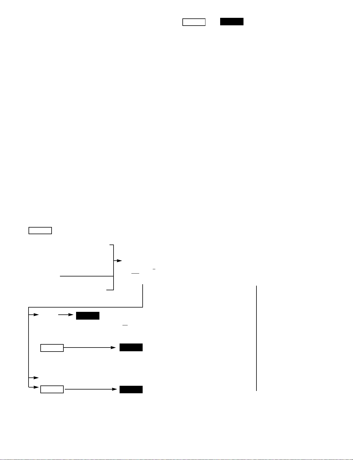
6.1 Choosing a wiring method for the receiver
Before starting work, it is essential to decide precisely where to fit the Receiver
Unit, and how you intend to wire it. i.e., which cable entry points you will use and
therefore how long the cable will need to be. There are 2 types of installation -
please choose the appropriate method for your situation:
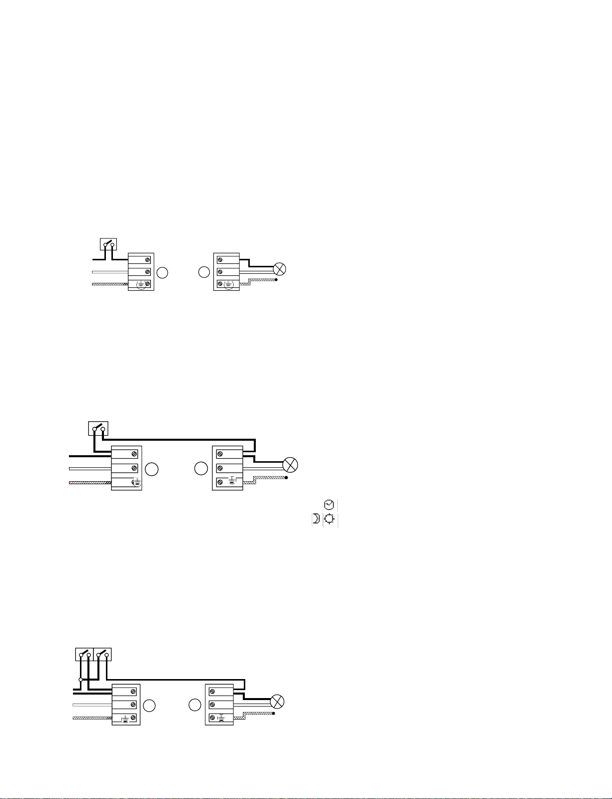
Wiring method A. Using existing cabling only
This approach is used when you wish to leave the existing power supply cabling to
a light fitting unchanged. The cable is cut at a convenient point and the receiver
connected to the cut cable ends.
Wiring method B. Using new or a combination of new and existing
cabling
This approach is used when new cabling is required throughout the installation, or
when only the cabling from the power supply or light fitting needs to be changed.
is important to take the following factors into account when deciding where
the receiver should go:
■The surface must be flat
■The power supply cable must be connected to terminalA
■The light fitting cable must be connected to terminal B
■The entry point hole next to terminal B cannot be used for the power supply
cable (shown in fig 1 as entry point 4)
Follow the instructions relevant to your installation
A. Using existing cabling only
IMPORTANT:Mains electricity supply must be turned off before cable is cut. If in doubt
consult a qualified electrician.
Choose a position for the Receiver Unit - which can be mounted horizon-
tally (fig 5) or vertically (fig 6)
This may be outdoors near the light fitting or perhaps indoors near the mains
supply consumer box. It’s important to remember that with only the cut existing
cable to work with you must fit the unit so that the cable entry holes 1 and 4 at
either end of the receiver can be used (See figs. 5 and 6).
Check there are no obstructions to fitting the unit in your chosen position.
Cut cable, making sure there is enough free cable either side of the cut to allow
connection to the Receiver’s
Cut cable, making sure there is enough free cable either side of the cut to allow
connection to the Receiver’s terminals.
Do not trim the cable ends yet.
B. Using new, or a combination of new and
existing cabling
IMPORTANT: Mains electricity supply must be turned off before cable is
cut. If in doubt consult a qualified electrician.
Choose a position for the Receiver Unit - which can be mounted vertically
(figs 7&8) or horizontally (fig 9)
Decide where the Receiver Unit is to be fixed and which cable entry points will be
used, checking that the cables will fit without obstructions.
Any of the cable entry points in the unit may be used (see examples in figs 7, 8
and 9), so long as the supply cable is connected to TERMINAL A and the cable to
the light or lights is connected to TERMINAL B. You can wire through the end entry
points or the rear entry point to suit the circumstance. Note that the entry hole
(No.4) next to TERMINAL B CANNOT be used for the supply cable.
Prepare the cable
Cut the existing cable to a convenient length for handling, yet with enough spare to
allow connection to the relevant terminal when Receiver box is in position.
Install the new length of cable, again leaving a generous amount spare at the
receiver box end.
D O N OT reconnect power yet.
6.2 Fitting and connecting the Receiver Unit
The following fitting instructions can be used for wiring method A or wiring
method B
Mark the position of the Receiver
■Remove the cover from the Receiver Unit.
■Place the receiver case in the required position, ensuring that it is on a flat
surface, and check
that both cables will be able to enter the chosen
entry holes.
■Mark the position of the fixing holes (fig 10).
Prepare access openings and drain hole
■The access openings in front of the cable entry holes can be enlarged by remov-
ing ‘knock outs’. If the cable to be passed through the access opening is too
large in diameter to fit, knock out the extra material with a small screwdriver to
create suitably larger openings. (See fig 11)
■If the rear access hole is chosen, use firm pressure with your screwdriver to
remove the knock out and create the hole. Clean up the edges of the hole with
a sharp knife to ensure a good seal for the grommet.
■Make sure that the pierced grommets are in position in the entry holes to be
used, and that the blank unpierced grommets are fitted in the other unused
entry points. Insert the grommets the correct way round. (See fig 12)
■There are two moisture drain holes - see fig 1. For your chosen installation,
determine which will be in the lower position when fitted. Open up this drain
hole to its full diameter using a small screwdriver or drill
(See fig 13)Fixing in place
■Drill holes where marked. If fitting against a masonry wall, drill holes using a
masonry drill bit to suit wall plug dimensions. Drill the holes to the required
depth and insert the wall plugs.
■Before fixing the receiver case in place, feed cable ends through pierced grom-
mets in the entry holes, being careful not to pull out the grommets.
■Push fixing screws through the sealing plugs (see fig 14) - ensuring that the
seals are correctly seated in the fixing holes - and screw receiver case to wall.
Connecting cable ends
■Cut the cable ends so they easily reach the terminals.
■Trim back the outer insulation to a convenient length, but allow at least 5mm to
remain protruding from the inside of the grommet when the cable is fed
through.
■If you’re fitting the cable to the light fitting(s) through an entry hole near TERMI-
NAL A, you must remove the outer insulation from the wires to allow them to fit
into the channel giving access to TERMINAL B (see figs 7 and 8).
■Strip the LIVE and NEUTRAL wires’ insulation to expose 6mm of bare copper
wire (if the wire is the stranded kind, twist the strands together so that no
strands fray).
■If the cable contains an insulated EARTH wire, strip this in the same way.
■Make a final check that the cables from the power source and the light fitting will
be connected at the correct ends of the Receiver Unit - (the power supply must
be connected to TERMINAL A, and the light fitting must be connected to TERMI-
NAL B).
■Connect both cable ends to their terminal blocks, inserting each separate wire
into the relevant terminal.
■For the cable from the supply, LIVE is connected to the L terminal, NEUTRAL is
fig 15
2 AUTO / ON
Wiring in this manner provides two lighting options:
Automatic operation - Switch open
Permanent ON - Switch closed
INDOOR SWITCH FOR ‘PERMANENT ON’ OVERRIDE
NOTE: To ensure watertight seals are maintained in the Receiver Unit, use a
separate cable entry hole & grommet for any additional cabling from the switch
A
L
NB
Lamp
LIVE
NEUTRAL
EARTH
LIVE
NEUTRAL
EARTH
PERMANENT OFF: - S1 OPEN S2 OPEN
AUTO MODE: - S1 CLOSED S2 OPEN
PERMANENT ON: - S1 OPEN OR CLOSED S2 CLOSED
fig 16
2 GANG SWITCH
S1 S2
3 AUTO / ON / OFF
Wiring in this manner provides three lighting options:
Automatic operation - Switch 1 closed, switch 2 open
Permanent OFF - Switch 1 open, switch 2 open
Permanent ON - Switch 1 open or closed, switch 2 closed
INDOOR SWITCH SINGLE POLE 2 GANG
NOTE: To ensure watertight seals are maintained in the Receiver Unit, use a separate
cable entry hole & grommet for any additional cabling from the switch
LIVE
NEUTRAL
EARTH
L
N
L1
N
A
L
N
L1
N
B
AB
Lamp
connected to the Nterminal and, the EARTH to the terminal.
■For the cable to the light fitting, LIVE is connected to the L1 terminal, the NEU-
TRAL to the Nterminal and, the EARTH to the terminal.
IMPORTANT:You must connect the earth wires to the earth terminals where
metal light fittings are used, to ensure the fittings are properly earthed.
System code and closing up
Set your system code if required (see Section 5 - Choosing your system code),
ensure the rubber waterproofing gasket is in position, screw the receiver cover in
place and connect the power supply.
6.3 Manual Override
By adding an indoor lightswitch to the wiring circuit, the connected light can also be
controlled manually. Depending on the option chosen the light can be turned off
permanently, or turned on permanently as an alternative to automatic operation.
1 AUTO / OFF
Wiring in this manner provides two lighting options:
Automatic operation - Switch closed
Permanent OFF - Switch open
INDOOR SWITCH FOR ‘PERMANENT OFF’OVERRIDE
7. PIR MOVEMENT DETECTOR FITTING INSTRUCTIONS
7.1 Where to position the PIR M ovement D etector
■Position the Wirefree PIR Detector anywhere within 50 metres of the Receiver Unit,
but avoid mounting it on or near a large metal object, on something which is likely to
move - such as a small tree or loose fence panel - or where the light can shine direct-
ly at the PIR Detector. Also avoid siting where the unit may detect any of the following:
heat sources (extractor fans, tumble dryer exhausts, etc.), reflective surfaces ( pools
of water, white-painted walls, etc.), nearby overhanging branches. (see fig 18)
■The ideal height to mount your PIR Detector is 2.5 metres, which makes the best
use of the unit’s detection zones as shown in the diagrams (see figs 19 and 20).
Mounting the PIR Detector in a higher position (maximum 4 metres) may give a
greater range, but the detection pattern will be less effective. The PIR Detector is
much more sensitive to movement across its field of vision (see fig 21A) than move-
ment directly towards it, so site the unit so that it looks across the normal approach
to your property.
■The Wirefree PIR Movement Detector has a swivel sensor head to allow you to
adjust the area of detection (See Testing Procedure in Section 8): tilting the
head upwards will increase the detection distance, tilting it downward will
reduce the detection distance. The sensor head will also turn to the left and
right (see figs 22 and 23).
■You can further tailor the detection area to suit your needs by using the slot-in
lens screening panels provided (see fig 24). To discover how much screening is
needed, first obscure the PIR unit’s lens with masking tape, progressively cover-
ing more of the lens until the required detection area is achieved. Then simply
cut a piece of the plastic screening to cover the same area as the tape, remove
the tape - being sure to remove any adhesive residue left behind - and slot the
screening into the PIR Detector (see fig 24)
N.B If in normal conditions you find that something such as a tree or shrub is
repeatedly activating the system, you can partially ‘mask’ the detector lens
with electrical tape to stop the detector ‘seeing’ the disturbance. As a guide,
the top half of the PIR Detector lens deals with long-range detection, the bot-
tom half is for short range. Alternatively, the PIR Detector can be easily re-
positioned in a more suitable location.
7.2 Fitting the Wirefree PIR Movement
Detector
NOTE:Before fixing the PIR unit to the mounting surface, it is advisable to
check that the system works correctly (i.e. that the transmitter and receiver
are within radio range of each other) by temporarily fixing the PIR Detector in
the chosen location.
■Open the PIR Detector by inserting a small slotted screwdriver into the slot at
the base of the unit. Push the screwdriver gently to release the catch and to
allow the front cover to be opened fully - the cover is hinged at the top (see fig 25).
■Check inside to identify the battery connector and the row of eight slider-switches
■If you changed the system code switch settings in the receiver unit (Section 5),
make sure you have set the same code in the PIR detector.
■Place the backplate of the unit in the desired position and mark the locations of the fix-
ing holes (see fig 27). Next, drill the holes to the required depth and insert the wall plugs.
■Clip a 9V PP3 (6LR61)ALKALINE battery to the connector and place the battery in its
holder (see fig 26).
■Fit the unit in place, close the cover and click it shut.
8. TESTING YOUR SYSTEM
Once your wirefree system is installed, test it by following the ‘Walk Test’ steps below.
1. Set the two adjustment controls on the underside of the PIR Detector as follows:
TIME - turn fully anticlockwise to min (see fig 29).
LUX - turn fully clockwise to max (see fig 30).
With these settings the system is in test mode and will work in full daylight. A small
red light (LED) behind the PIR detector lens will illuminate briefly each time move-
ment in front of the PIR is detected.
2. Ensure mains power is being supplied to the Receiver Unit.
3. Walk across the detection area approximately 5 metres from the PIR Detector.
As you walk through the first detection zone, the LED should light up. Now
stand still until the LED goes out - this should take about 1 second. The light
fitting wired to the Receiver Unit will also turn on for 3 seconds.
4. Start moving again. As you cross each zone the LED and light fitting should
illuminate as in step 3.
5. Repeat steps 3 and 4, walking at various distances and angles to the unit. This
will enable you to discover the detection pattern.
6. If the detection area is too small for your requirements, angle the PIR Detector
head up - this should increase the coverage distance. Similarly, angling the head
downwards will reduce the range. The tilt and swivel head also allows you to move
the unit from side to side, for further adjustment of the detection area. For more
unusual requirements, such as extremely short range, you may need to ‘mask’ an
area of the sensor lens - see Section 7.1.
9. SETTING FOR AU TO M ATIC OPERATION
Having completed the ‘walk test’ procedure, you can set the unit for automatic
operation as follows:
■Adjust the TIME control to the setting you require. This controls the length of
time the security light stays on once activated, after all motion stops. The mini-
mum time (control set fully anticlockwise) is about 15 seconds; the maximum
(control set fully clockwise) is approximately 15 minutes. Set the control at
whichever timing suits you between these limits. See fig. 31 for approximate
position of time settings.
N
L1
Lamp
fig 17
N.B. Remember that the time you set relates to how long the lamp remains on after
all motion stops. If someone triggers your lamp it will remain on for as long as that
person keeps moving in the detection area, then continue to illuminate for the tim-
ing you have set after all motion stops.
■The ‘LUX’ control enables you to set the system to become active when a cer-
tain level of darkness has fallen each evening. Set the LUX by turning the con-
trol fully anticlockwise, and wait until darkness begins to fall. When it is dark
enough for you to want the lamp to be operative, turn the LUX control clockwise
slightly, move your hand slowly in front of the PIR, turn the LUX control a little
more and repeat the procedure until the light activates. Leave the control set at
this point.
■If after a few nights you decide the system is starting too early, turn the LUX
control slightly anticlockwise. Or if it starts too late, turn clockwise.
10. BATTERY REPLACEMENT
The PP3 9 volt battery should provide the PIR Detector with around 18 months
operation*. When the battery is nearing the end of its life - about 30 days before
failure - the PIR Detector sends a message to the receiver,
EACH TIME IT IS ACTI-
VATED so that THE LIGHT BRIEFLY TURNS ON, THEN OFF THEN ON AGAIN IN
QUICK SUCCESSION. THIS NOTIFIES YOU TO CHANGE THE BATTERY.
As this ‘change battery’ message will not occur for some time and you may forget
about it in the future, we have included a reminder sticker which should be posi-
tioned in a prominent place.
*Depending on the number of activations each day and the effect of low temperatures.
11. EXTENDING THE SYSTEM
To extend your wirefree automatic lighting system, additional PIR Detectors can be pur-
chased to extend the area of intruder detection. Further PIR Detector and Receiver kits
can be installed to operate on different system codes. This allows you to ‘zone’ your
security lighting, so for instance, you can cover a distant outbuilding or secondary
access to your property without having lights turning on elsewhere. Remember that if
you have more than one PIR Detector in the same system (set with the same system
code), the light or lights will stay on until the last detector no longer detects any move-
ment, and then continue to be illuminated for the duration of the ‘light on’timing you have
chosen.
12. CLEANING
Occasionally use a soft damp cloth to gently clean the PIR unit lens, and the plastic
cases of both the PIR unit and receiver. Take care not to accidentally move the detector
head.
13. FA U LT FINDING
If your wirefree system fails to work properly, complete the relevant test or tests
which follow.
PROBLEM
Confir m that bulb, mains supply, and
batter y are operating cor rectly.Also
ensure that the system codes in
each unit match, and that the PIR is
within the operating range of 50
metres.IfalltheseareOK,gotothe
nextstage.
Although this is most likely to be
an incor rectluxsetting,first
confir m that there is not another
cause by following the next step.
TEST THE SYSTEM’S
OPERATION
Car ry out a ‘WalkTest’(see
section 8). This allows you to
check that the PIR is function -
ing, when itisfunctioningand
whether the R eceiverispicking
upitssignal.
Settimingcontrolbackasitwas and setluxcontroltoa‘brighter’
setting than before.The conditions may have generally
beentoobrightforthedetectorsetting.Aninter mittent problem may
alsobeduetooccasionalradiointerferance.
SOLUTION
Try repositioning the detector to
allow a stronger signal to reach
theReceiver.
…Ever
…A t night
Light does not operate when it should…
SOLUTION
Try repositioning or adjusting the
angle or direction of the PIR head.
…Intermittently
SOLUTION
TEST OK
The PIR ‘view’may be obscured by objects that
par tially hide persons to be detected
(e.g. posts, pillars). The PIR position or sensor
alignment may need adjusting.
PROBLEM
PIR does not detect properly
Radiotransmissionisnotbeingreceived
duetodistanceorobstructionsorradio
interference.Alsolargemetalobjects
(includingvehicles)closetotheDetector
TransmitterorReceiverUnitcancausethis.
PROBLEM
PIR detects effectively but light
doesn’t operate
PROBLEM SOLUTION
■ The PIR Detector may be suffering from false activation.
Check this by completely covering the Detector’s lens
with a thick cloth, masking tape or a piece of cardboard.
This will stop the Detector ‘seeing’ anything. If the
Detector now lets the light switch off after the set time
and does not light it again, this indicates that the sensor
has been picking up movement within its range. Slightly
adjust the position/angle of the PIR Detector to solve the
problem. Masking the area of the lens corresponding to
the location of the interference is another solution; and
since the PIR Detector is wirefree, even moving it to a
new location is easy.
■The level of light at the Detector may be too low for the
current photocell LUX setting, activating the unit as
though it were night-time. In normal daylight, adjust the
LUX control slightly anticlockwise. Wait outside the detec-
tion area until the light goes out, then re-enter it. If the
PIR Detector still activates, the LUX setting is still too
high. Adjust and test again until the unit stops activating
the light.
■ The PIR Detector operates by sensing temperature dif-
ferences. On a cold winter’s night, body heat stands out
more contrastingly from the surrounding cold conditions,
so the PIR Detector is more effective. On a warm night
the contrast is not so great, and the detector is less
effective. For this reason, it may be necessary to make
seasonal adjustments to the PIR Detector.
■ The PIR Detector may be suffering from false activation.
Check this by completely covering the detector’s lens
with a thick cloth, masking tape or a piece of cardboard.
This will stop the Detector ‘seeing’ anything. If the
Detector now lets the light switch off after the set time
and does not light it again, this indicates that the sensor
has been picking up movement within its range. Slightly
adjust the position/angle of the PIR Detector to solve the
problem. Masking the area of the lens corresponding to
the location of the disturbance is another solution; and
since the PIR detector is wirefree, even moving it to a
new location is easy.
■Wind may be activating the detector, due to where it is
sited; try it in a different location.
■ Small animals and pets may be affecting the unit - try
masking the bottom half of the lens to stop the Detector
from picking up low level objects.
■ Also check that the PIR Detector is not sensing move-
ment from nearby traffic or pedestrians. Alternatively, for
the above problems, check if a nearby wirefree system is
operating with the same code. In this instance the light
would still operate if the detector lens was completely
masked off or if the battery was removed - change the
coding if necessary.
Light stays on
continually at
night.
PIR Detector
activates the
light in day-
time.
Detection range
varies from day
to day.
Light activates
for
no obvious rea-
son,
at random.
14. TECHNICAL SPECIFICATIONS
G UARANTEE
Friedland Limited guarantee that should any defects in workmanship or materials occur in this product within 3
years from the date of purchase, it will be replaced provided it has not been dismantled, altered, or a repair attempt-
ed. To comply with the 3 year guarantee, the installation and usage of the product must be in accordance with the
Technical Specification above and in particular, care should be taken to ensure the maximum switching loads are
not exceeded. The product should be returned to place of purchase along with this manual, the purchase receipt
and details of circumstances of the malfunction given. This undertaking is in addition to the consumer’s statutory
rights and does not affect these rights in any way.
Friedland Limited, Houldsworth Street, Stockport, Cheshire SK5 6BP, England
RECEIVER UNIT
Power supply - 220 - 240 volt
AC 50Hz
Switching capacity -1000W tungsten
filament, 1000W
tungsten halogen
lighting (2 amp
inductive loads)
Temperature
operating range --20°C to +50°C
PIR MOVEMENT DETECTOR
Transmitter range - Up to 50 metres
Detection range - Up to 12 metres
Angle of detection - 140°
Detector battery life - Minimum 18 mths,
at 8 activations
per day and
constant 15°C
Battery type - PP3 (6LR61) 9
volt alkaline
Time on adjustment - 15 secs - 15 mins
Photocell
adjustment - 5 lux to daylight
Temperature
operating range - -20°C to +35°C

Other FRIEDLAND Security Sensor manuals

FRIEDLAND Spectra Plus L420N WHI User manual

FRIEDLAND

FRIEDLAND Spectra Plus L420N WHI User manual

FRIEDLAND Spectra Plus L420N WHI User manual

FRIEDLAND

FRIEDLAND Spectra Plus L420N WHI User manual

FRIEDLAND Magnetic Contact User manual

FRIEDLAND

FRIEDLAND Magnetic Contact User manual

FRIEDLAND Spectra Lite L230N BLK User manual

FRIEDLAND

FRIEDLAND Spectra Lite L230N BLK User manual

FRIEDLAND SPECTRA Lite User manual

FRIEDLAND

FRIEDLAND SPECTRA Lite User manual

FRIEDLAND D918S Libra+ User manual

FRIEDLAND

FRIEDLAND D918S Libra+ User manual

FRIEDLAND SPECTRA 140 User manual

FRIEDLAND

FRIEDLAND SPECTRA 140 User manual

FRIEDLAND Spectra Wirefree Product information sheet

FRIEDLAND

FRIEDLAND Spectra Wirefree Product information sheet

Popular Security Sensor manuals by other brands

HELVAR digidim 313 installation guide

HELVAR

HELVAR digidim 313 installation guide

Satel FD-1 quick start guide

Satel

Satel FD-1 quick start guide

SILENTRON PhotoPir 5525 manual

SILENTRON

SILENTRON PhotoPir 5525 manual

B.E.G. LUXOMAT PD4-DIM Installation and operating instruction

B.E.G.

B.E.G. LUXOMAT PD4-DIM Installation and operating instruction

First Alert Carbon Monoxide Alarm user manual

First Alert

First Alert Carbon Monoxide Alarm user manual

Crow FREEWAVE FW-P100 installation instructions

Crow

Crow FREEWAVE FW-P100 installation instructions

Potter PAD100-DUCT installation manual

Potter

Potter PAD100-DUCT installation manual

LEGRAND 488 20 manual

LEGRAND

LEGRAND 488 20 manual

NA-DE 10431 quick start guide

NA-DE

NA-DE 10431 quick start guide

Honeywell Miller Falcon MP50G-LE User instruction

Honeywell

Honeywell Miller Falcon MP50G-LE User instruction

GTO LOOPDT1 reference guide

GTO

GTO LOOPDT1 reference guide

Industrial Scientific VX500 instruction manual

Industrial Scientific

Industrial Scientific VX500 instruction manual

Sri 210D manual

Sri

Sri 210D manual

Kistler 6021B Series instruction manual

Kistler

Kistler 6021B Series instruction manual

Bosch Smart Home RFPR-ZB-SH-EU quick start guide

Bosch

Bosch Smart Home RFPR-ZB-SH-EU quick start guide

JCM Technologies CAP T868 user manual

JCM Technologies

JCM Technologies CAP T868 user manual

DELTA DORE TYXAL DF installation guide

DELTA DORE

DELTA DORE TYXAL DF installation guide

Gira 2050 Series operating instructions

Gira

Gira 2050 Series operating instructions

manuals.online logo
manuals.online logoBrands
  • About & Mission
  • Contact us
  • Privacy Policy
  • Terms and Conditions

Copyright 2025 Manuals.Online. All Rights Reserved.